

SL280DFV Gas Furnace Installation Manual - Lennox
SL280DFV Gas Furnace Installation Manual - Lennox
SL280DFV Gas Furnace Installation Manual - Lennox

You also want an ePaper? Increase the reach of your titles
YUMPU automatically turns print PDFs into web optimized ePapers that Google loves.
Generator Use − Voltage Requirements<br />
The following requirements must be kept in mind when<br />
specifying a generator for use with this equipment:<br />
The furnace requires 120 volts (Range: 102 volts to<br />
132 volts)<br />
The furnace operates at 60 Hz + 5% (Range: 57 Hz to<br />
63 Hz)<br />
<br />
<br />
The furnace integrated control requires both correct<br />
polarity and proper ground. Both polarity and proper<br />
grounding should be checked before attempting to operate<br />
the furnace on either permanent or temporary<br />
power<br />
Generator should have a wave form distortion of less<br />
than 5% THD (total harmonic distortion)<br />
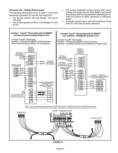
icomfort Touch ® Thermostat with <strong>SL280DFV</strong><br />
and Non−Communicating Outdoor Unit<br />
icomfort Touch ® Thermostat<br />
icomfort−Enabled <strong>SL280DFV</strong> Indoor <strong>Furnace</strong><br />
Non−Communicating Outdoor Air Conditioner<br />
icomfort Touch ® Thermostat with <strong>SL280DFV</strong><br />
and icomfort−ENABLED Outdoor Unit<br />
icomfort Touch ® Thermostat<br />
icomfort−Enabled <strong>SL280DFV</strong> Indoor <strong>Furnace</strong><br />
icomfort−Enabled Outdoor Air Conditioner or Heat Pump<br />
OPTIONAL<br />
DISCHARGE<br />
AIR SENSOR<br />
icomfort Touch®<br />
THERMOSTAT<br />
icomfort−<br />
ENABLED<br />
<strong>SL280DFV</strong><br />
FURNACE<br />
OPTIONAL<br />
OUTDOOR<br />
AIR SENSOR<br />
OPTIONAL<br />
DISCHARGE<br />
AIR SENSOR<br />
OPTIONAL<br />
OUTDOOR<br />
AIR SENSOR<br />
icomfort Touch®<br />
THERMOSTAT<br />
icomfort−<br />
ENABLED<br />
<strong>SL280DFV</strong><br />
FURNACE<br />
icomfort− ENABLED<br />
OUTDOOR AIR CONDITIONING<br />
OR HEAT PUMP UNIT<br />
NON−COMMUNICATING<br />
OUTDOOR AIR<br />
CONDITIONING UNIT −<br />
1 OR 2 STAGE<br />
CLIP ON−BOARD LINK<br />
W915 (Y1 TO Y2) FOR<br />
TWO−STAGE OPERATION<br />
NOTE − On communicating systems, extra wires must terminate on the "C" RSBus terminal. Use an additional wire and come<br />
off "C" terminal and wire nut all the extra wires together. Termination on the outdoor control must match the indoor control.<br />
Outdoor Unit<br />
icomfort Integrated Control<br />
icomfort Touch ®<br />
FIGURE 21<br />
Page 23


