

SL280DFV Gas Furnace Installation Manual - Lennox
SL280DFV Gas Furnace Installation Manual - Lennox
SL280DFV Gas Furnace Installation Manual - Lennox

You also want an ePaper? Increase the reach of your titles
YUMPU automatically turns print PDFs into web optimized ePapers that Google loves.
12− If the appliance will not operate, follow the instructions<br />
Turning Off <strong>Gas</strong> to Unit" and call your service technician<br />
or gas supplier.<br />
Turning Off <strong>Gas</strong> to Unit<br />
1 − Set the thermostat to the lowest setting.<br />
2 − Turn off all electrical power to the unit if service is to be<br />
performed.<br />
3 − Remove the upper access panel.<br />
4 − Move switch on gas valve to OF. Do not force. See figure<br />
26 or 27.<br />
5 − Replace the upper access panel.<br />
Failure To Operate<br />
If the unit fails to operate, check the following:<br />
1 − Is the thermostat calling for heat?<br />
2 − Are access panels securely in place?<br />
3 − Is the main disconnect switch closed?<br />
4 − Is there a blown fuse or tripped circuit breaker?<br />
5 − Is the filter dirty or plugged? Dirty or plugged filters will<br />
cause the limit control to shut the unit off.<br />
6 − Is gas turned on at the meter?<br />
7 − Is the manual main shut-off valve open?<br />
8 − Is the internal manual shut-off valve open?<br />
9 − Is the unit ignition system in lock out? If the unit locks out<br />
again, call the service technician to inspect the unit for<br />
blockages.<br />
10 −Is pressure switch closed? Obstructed flue will cause<br />
unit to shut off at pressure switch. Check flue and outlet<br />
for blockages.<br />
11 −Is the rollout switch tripped? If the switch is tripped call<br />
the service technician to inspect the unit.<br />
<strong>Gas</strong> Pressure Adjustment<br />
<strong>Gas</strong> Flow (Approximate)<br />
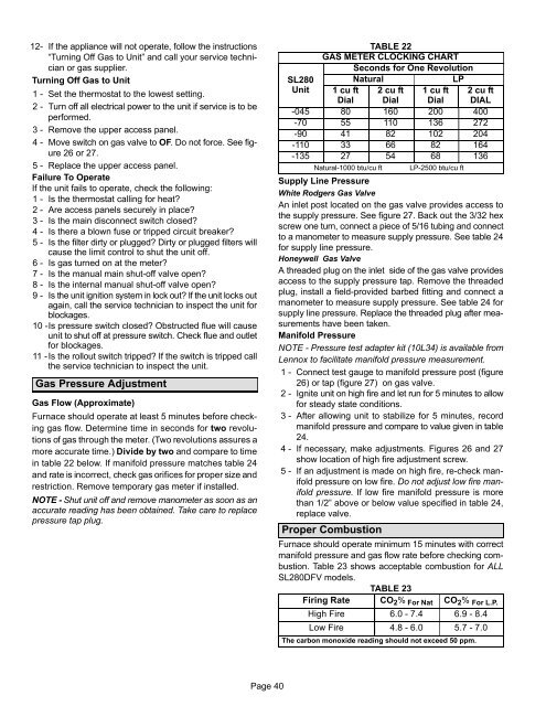
<strong>Furnace</strong> should operate at least 5 minutes before checking<br />
gas flow. Determine time in seconds for two revolutions<br />
of gas through the meter. (Two revolutions assures a<br />
more accurate time.) Divide by two and compare to time<br />
in table 22 below. If manifold pressure matches table 24<br />
and rate is incorrect, check gas orifices for proper size and<br />
restriction. Remove temporary gas meter if installed.<br />
NOTE − Shut unit off and remove manometer as soon as an<br />
accurate reading has been obtained. Take care to replace<br />
pressure tap plug.<br />
TABLE 22<br />
GAS METER CLOCKING CHART<br />
Seconds for One Revolution<br />
SL280 Natural<br />
LP<br />
Unit 1 cu ft 2 cu ft 1 cu ft 2 cu ft<br />
Dial Dial Dial DIAL<br />
−045 80 160 200 400<br />
−70 55 110 136 272<br />
−90 41 82 102 204<br />
−110 33 66 82 164<br />
−135 27 54 68 136<br />
Natural−1000 btu/cu ft LP−2500 btu/cu ft<br />
Supply Line Pressure<br />
White Rodgers <strong>Gas</strong> Valve<br />
An inlet post located on the gas valve provides access to<br />
the supply pressure. See figure 27. Back out the 3/32 hex<br />
screw one turn, connect a piece of 5/16 tubing and connect<br />
to a manometer to measure supply pressure. See table 24<br />
for supply line pressure.<br />
Honeywell <strong>Gas</strong> Valve<br />
A threaded plug on the inlet side of the gas valve provides<br />
access to the supply pressure tap. Remove the threaded<br />
plug, install a field−provided barbed fitting and connect a<br />
manometer to measure supply pressure. See table 24 for<br />
supply line pressure. Replace the threaded plug after measurements<br />
have been taken.<br />
Manifold Pressure<br />
NOTE − Pressure test adapter kit (10L34) is available from<br />
<strong>Lennox</strong> to facilitate manifold pressure measurement.<br />
1 − Connect test gauge to manifold pressure post (figure<br />
26) or tap (figure 27) on gas valve.<br />
2 − Ignite unit on high fire and let run for 5 minutes to allow<br />
for steady state conditions.<br />
3 − After allowing unit to stabilize for 5 minutes, record<br />
manifold pressure and compare to value given in table<br />
24.<br />
4 − If necessary, make adjustments. Figures 26 and 27<br />
show location of high fire adjustment screw.<br />
5 − If an adjustment is made on high fire, re−check manifold<br />
pressure on low fire. Do not adjust low fire manifold<br />
pressure. If low fire manifold pressure is more<br />
than 1/2" above or below value specified in table 24,<br />
replace valve.<br />
Proper Combustion<br />
<strong>Furnace</strong> should operate minimum 15 minutes with correct<br />
manifold pressure and gas flow rate before checking combustion.<br />
Table 23 shows acceptable combustion for ALL<br />
<strong>SL280DFV</strong> models.<br />
TABLE 23<br />
Firing Rate CO 2 % For Nat CO 2 % For L.P.<br />
High Fire 6.0 − 7.4 6.9 − 8.4<br />
Low Fire 4.8 − 6.0 5.7 − 7.0<br />
The carbon monoxide reading should not exceed 50 ppm.<br />
Page 40


