

SL280DFV Gas Furnace Installation Manual - Lennox
SL280DFV Gas Furnace Installation Manual - Lennox
SL280DFV Gas Furnace Installation Manual - Lennox

Create successful ePaper yourself
Turn your PDF publications into a flip-book with our unique Google optimized e-Paper software.
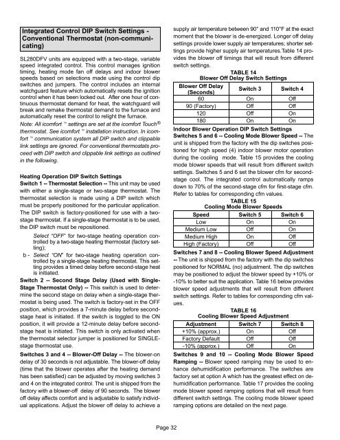
Integrated Control DIP Switch Settings −<br />
Conventional Thermostat (non−communicating)<br />
<strong>SL280DFV</strong> units are equipped with a two−stage, variable<br />
speed integrated control. This control manages ignition<br />
timing, heating mode fan off delays and indoor blower<br />
speeds based on selections made using the control dip<br />
switches and jumpers. The control includes an internal<br />
watchguard feature which automatically resets the ignition<br />
control when it has been locked out. After one hour of continuous<br />
thermostat demand for heat, the watchguard will<br />
break and remake thermostat demand to the furnace and<br />
automatically reset the control to relight the furnace.<br />
Note: All icomfort settings are set at the icomfort Touch ®<br />
thermostat. See icomfort installation instruction. In icomfort<br />
communication system all DIP switch and clippable<br />
link settings are ignored. For conventional thermostats proceed<br />
with DIP switch and clippable link settings as outlined<br />
in the following.<br />
Heating Operation DIP Switch Settings<br />
Switch 1 −− Thermostat Selection −− This unit may be used<br />
with either a single−stage or two−stage thermostat. The<br />
thermostat selection is made using a DIP switch which<br />
must be properly positioned for the particular application.<br />
The DIP switch is factory−positioned for use with a two−<br />
stage thermostat. If a single−stage thermostat is to be used,<br />
the DIP switch must be repositioned.<br />
Select OFF" for two−stage heating operation controlled<br />
by a two−stage heating thermostat (factory setting);<br />
b − Select ON" for two−stage heating operation controlled<br />
by a single−stage heating thermostat. This setting<br />
provides a timed delay before second−stage heat<br />
is initiated.<br />
Switch 2 −− Second Stage Delay (Used with Single−<br />
Stage Thermostat Only) −− This switch is used to determine<br />
the second stage on delay when a single−stage thermostat<br />
is being used. The switch is factory−set in the OFF<br />
position, which provides a 7−minute delay before second−<br />
stage heat is initiated. If the switch is toggled to the ON<br />
position, it will provide a 12−minute delay before second−<br />
stage heat is initiated. This switch is only activated when<br />
the thermostat selector jumper is positioned for SINGLE−<br />
stage thermostat use.<br />
Switches 3 and 4 −− Blower−Off Delay −− The blower−on<br />
delay of 30 seconds is not adjustable. The blower−off delay<br />
(time that the blower operates after the heating demand<br />
has been satisfied) can be adjusted by moving switches 3<br />
and 4 on the integrated control. The unit is shipped from the<br />
factory with a blower−off delay of 90 seconds. The blower<br />
off delay affects comfort and is adjustable to satisfy individual<br />
applications. Adjust the blower off delay to achieve a<br />
supply air temperature between 90° and 110°F at the exact<br />
moment that the blower is de−energized. Longer off delay<br />
settings provide lower supply air temperatures; shorter settings<br />
provide higher supply air temperatures.Table 14 provides<br />
the blower off timings that will result from different<br />
switch settings.<br />
TABLE 14<br />
Blower Off Delay Switch Settings<br />
Blower Off Delay<br />
Switch 3 Switch 4<br />
(Seconds)<br />
60 On Off<br />
90 (Factory) Off Off<br />
120 Off On<br />
180 On On<br />
Indoor Blower Operation DIP Switch Settings<br />
Switches 5 and 6 −− Cooling Mode Blower Speed −− The<br />
unit is shipped from the factory with the dip switches positioned<br />
for high speed (4) indoor blower motor operation<br />
during the cooling mode. Table 15 provides the cooling<br />
mode blower speeds that will result from different switch<br />
settings. Switches 5 and 6 set the blower cfm for second−<br />
stage cool. The integrated control automatically ramps<br />
down to 70% of the second−stage cfm for first−stage cfm.<br />
Refer to tables for corresponding cfm values.<br />
TABLE 15<br />
Cooling Mode Blower Speeds<br />
Speed Switch 5 Switch 6<br />
Low On On<br />
Medium Low Off On<br />
Medium High On Off<br />
High (Factory) Off Off<br />
Switches 7 and 8 −− Cooling Blower Speed Adjustment<br />
−− The unit is shipped from the factory with the dip switches<br />
positioned for NORMAL (no) adjustment. The dip switches<br />
may be positioned to adjust the blower speed by +10% or<br />
−10% to better suit the application. Table 16 below provides<br />
blower speed adjustments that will result from different<br />
switch settings. Refer to tables for corresponding cfm values.<br />
TABLE 16<br />
Cooling Blower Speed Adjustment<br />
Adjustment Switch 7 Switch 8<br />
+10% (approx.) On Off<br />
Factory Default Off Off<br />
−10% (approx.) Off On<br />
Switches 9 and 10 −− Cooling Mode Blower Speed<br />
Ramping −− Blower speed ramping may be used to enhance<br />
dehumidification performance. The switches are<br />
factory set at option A which has the greatest effect on de−<br />
humidification performance. Table 17 provides the cooling<br />
mode blower speed ramping options that will result from<br />
different switch settings. The cooling mode blower speed<br />
ramping options are detailed on the next page.<br />
Page 32


