1310.chp:Corel VENTURA - Tyco Fire Products
1310.chp:Corel VENTURA - Tyco Fire Products
1310.chp:Corel VENTURA - Tyco Fire Products

Create successful ePaper yourself
Turn your PDF publications into a flip-book with our unique Google optimized e-Paper software.
Page8of16<br />
TFP1310<br />
Valve<br />
Size<br />
1-1/2"<br />
(DN40)<br />
2"<br />
(DN50)<br />
3"<br />
(DN80)<br />
4"<br />
(DN100)<br />
6"<br />
(DN150)<br />
8"<br />
(DN200)<br />
A<br />
7.00<br />
(177,8)<br />
7.13<br />
(181,0)<br />
7.81<br />
(198,4)<br />
10.00<br />
(254,0)<br />
11.38<br />
(289,0)<br />
12.00<br />
(304,8)<br />
B<br />
8.88<br />
(225,4)<br />
9.13<br />
(231,8)<br />
10.44<br />
(265,1)<br />
11.75<br />
(298,5)<br />
14.31<br />
(363,5)<br />
16.00<br />
(406,4)<br />
C<br />
13.19<br />
(335,0)<br />
13.19<br />
(335,0)<br />
13.19<br />
(335,0)<br />
14.31<br />
(363,5)<br />
15.31<br />
(388,9)<br />
16.25<br />
(412,8)<br />
Nominal Installation Dimensions in Inches and (mm)<br />
D E F G H J<br />
10.50<br />
(266,7)<br />
10.50<br />
(266,7)<br />
10.50<br />
(266,7)<br />
10.50<br />
(266,7)<br />
10.50<br />
(266,7)<br />
10.50<br />
(266,7)<br />
15.25<br />
(387,4)<br />
15.56<br />
(395,3)<br />
19.13<br />
(485,8)<br />
22.13<br />
(562,0)<br />
23.31<br />
(592,1)<br />
25.50<br />
(647,7)<br />
1.25<br />
(31,8)<br />
0.94<br />
(23,8)<br />
1.63<br />
(41,3)<br />
1.75<br />
(44,5)<br />
3.50<br />
(88,9)<br />
1.75<br />
(44,5)<br />
5.81<br />
(147,6)<br />
6.00<br />
(152,4)<br />
6.69<br />
(170,0)<br />
8.56<br />
(217,5)<br />
9.94<br />
(252,4)<br />
10.75<br />
(273,1)<br />
1.81<br />
(46,0)<br />
2.00<br />
(50,8)<br />
2.69<br />
(68,3)<br />
4.44<br />
(112,7)<br />
5.81<br />
(147,6)<br />
6.50<br />
(165,1)<br />
3.00<br />
(76,2)<br />
3.00<br />
(76,2)<br />
4.25<br />
(108,0)<br />
6.25<br />
(158,8)<br />
6.25<br />
(158,8)<br />
6.25<br />
(158,8)<br />
K<br />
7.00<br />
(177,8)<br />
7.00<br />
(177,8)<br />
7.00<br />
(177,8)<br />
7.13<br />
(181,0)<br />
7.13<br />
(181,0)<br />
7.13<br />
(181,0)<br />
L<br />
3.88<br />
(98,4)<br />
3.00<br />
(76,2)<br />
0.88<br />
(22,2)<br />
0.63<br />
(15,9)<br />
1.81<br />
(46,0)<br />
7.38<br />
(187,3)<br />
M<br />
8.00<br />
(204,0)<br />
8.63<br />
(220,0)<br />
12.75<br />
(324,0)<br />
15.75<br />
(400,0)<br />
18.13<br />
(460,4)<br />
22.50<br />
(570,0)<br />
* MINIMUM CLEARANCE.<br />
A<br />
* * *<br />
B<br />
1/2" NPS<br />
WET PILOT<br />
LINE<br />
C<br />
D<br />
1/2" NPS<br />
DIAPHRAGM<br />
CHAMBER SUPPLY<br />
CONNECTING TRIM<br />
(FIELD FABRICATED)<br />
L<br />
M<br />
E<br />
*<br />
F<br />
G<br />
H<br />
MAIN<br />
CONTROL<br />
VALVE<br />
2" NPS<br />
DRAIN<br />
J<br />
K<br />
1-1/4" NPS<br />
DRAIN<br />
LEFT VIEW<br />
FRONT VIEW<br />
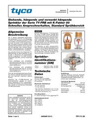
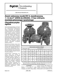
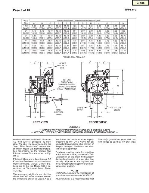
FIGURE 3<br />
1-1/2 thru 8 INCH (DN40 thru DN200) MODEL DV-5 DELUGE VALVE<br />
— VERTICAL WET PILOT ACTUATION / NOMINAL INSTALLATION DIMENSIONS —<br />
stations interconnected with minimum<br />
1/2 inch (DN15) Schedule 40 steel<br />
pipe. The pilot line is connected to the<br />
“Wet Pilot Detection” connection<br />
shown in Figure 2B. Nominal installation<br />
dimensions for the Vertical Wet<br />
Pilot Actuation Trim are shown in Figure<br />
3.<br />
Pilot sprinklers are to be minimum 5.6<br />
K-factor orifice listed or approved automatic<br />
sprinklers. Manual Control Stations<br />
are to be the Model MC-1 described<br />
in Technical Data Sheet<br />
TD1382.<br />
The maximum height of a wet pilot line<br />
above the DV-5 Valve must not exceed<br />
the limitations shown in Graph A as a<br />
function of the minimum water supply<br />
pressure to the DV-5 Valve for an<br />
equivalent length (pipe plus fittings) of<br />
the pilot line up to 500 feet to the most<br />
remote pilot sprinkler.<br />
Provision must be made for installing<br />
a 5.6 K-factor orifice, Inspector’s Test<br />
Connection at the most hydraulically<br />
demanding location of a wet pilot line<br />
(usually adjacent to the highest and<br />
most remote wet pilot sprinkler or manual<br />
control station).<br />
NOTES<br />
Wet Pilot Lines must be maintained at<br />
a minimum temperature of 40°F/4°C.<br />
At a minimum, it is recommended that<br />
internally galvanized pipe and cast<br />
iron fittings be used for wet pilot lines.