1310.chp:Corel VENTURA - Tyco Fire Products
1310.chp:Corel VENTURA - Tyco Fire Products
1310.chp:Corel VENTURA - Tyco Fire Products

You also want an ePaper? Increase the reach of your titles
YUMPU automatically turns print PDFs into web optimized ePapers that Google loves.
Technical Services: Tel: (800) 381-9312 / Fax: (800) 791-5500<br />
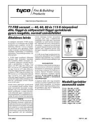
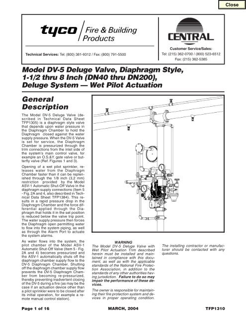
Model DV-5 Deluge Valve, Diaphragm Style,<br />
1-1/2 thru 8 Inch (DN40 thru DN200),<br />
Deluge System — Wet Pilot Actuation<br />
Customer Service/Sales:<br />
Tel: (215) 362-0700 / (800) 523-6512<br />
Fax: (215) 362-5385<br />
General<br />
Description<br />
The Model DV-5 Deluge Valve (described<br />
in Technical Data Sheet<br />
TFP1305) is a diaphragm style valve<br />
that depends upon water pressure in<br />
the Diaphragm Chamber to hold the<br />
Diaphragm closed against the water<br />
supply pressure. When the DV-5 Valve<br />
is set for service, the Diaphragm<br />
Chamber is pressurized through the<br />
trim connections from the inlet side of<br />
the system’s main control valve, for<br />
example an O.S.&Y. gate valve or butterfly<br />
valve (Ref. Figures 1 and 3).<br />
Opening of a wet pilot sprinkler, releases<br />
water from the Diaphragm<br />
Chamber faster than it can be replenished<br />
through the 1/8 inch (3,2 mm)<br />
restriction provided by the Model<br />
ASV-1 Automatic Shut-Off Valve in the<br />
diaphragm supply connections (Item 5<br />
- Fig. 2A and 4, also described in Technical<br />
Data Sheet TFP1384). This results<br />
in a rapid pressure drop in the<br />
Diaphragm Chamber and the force differential<br />
applied through the Diaphragm<br />
that holds it in the set position<br />
is reduced below the valve trip point.<br />
The water supply pressure then forces<br />
the Diaphragm open permitting water<br />
to flow into the system piping, as well<br />
as through the Alarm Port to actuate<br />
the system alarms.<br />
As water flows into the system, the<br />
pilot chamber of the Model ASV-1<br />
Automatic Shut-Off Valve (Item 5 - Fig.<br />
2A and 4) becomes pressurized and<br />
the ASV-1 automatically shuts off the<br />
diaphragm chamber supply flow to the<br />
DV-5 Diaphragm Chamber. Shutting<br />
off the diaphragm chamber supply flow<br />
prevents the DV-5 Diaphragm Chamber<br />
from becoming re-pressurized,<br />
thereby preventing inadvertent closing<br />
oftheDV-5duringafire(asmaybethe<br />
case if an actuation device other than<br />
a pilot sprinkler were to be closed after<br />
its initial operation, for example a remote<br />
manual control station).<br />
Page 1 of 16<br />
WARNING<br />
The Model DV-5 Deluge Valve with<br />
Wet Pilot Actuation Trim described<br />
herein must be installed and maintained<br />
in compliance with this document,<br />
as well as with the applicable<br />
standards of the National <strong>Fire</strong> Protection<br />
Association, in addition to the<br />
standards of any other authorities having<br />
jurisdiction. Failure to do so may<br />
impair the performance of these devices.<br />
The owner is responsible for maintaining<br />
their fire protection system and devices<br />
in proper operating condition.<br />
MARCH, 2004<br />
The installing contractor or manufacturer<br />
should be contacted with any<br />
questions.<br />
TFP1310
Page2of16<br />
TFP1310<br />
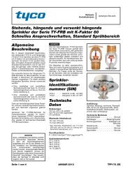
FIGURE1—PART1OF2<br />
SYSTEM SCHEMATIC (Front View) — WET PILOT ACTUATION
TFP1310<br />
Page 3 of 16<br />
FIGURE 1 — PART 2 OF 2<br />
SYSTEM SCHEMATIC (Rear View) — WET PILOT ACTUATION
Page4of16<br />
TFP1310<br />
NO. DESCRIPTION QTY. P/N<br />
1 300 psi/ 2000 kPa<br />
Water Pressure Gauge . . 2 92-343-1-005<br />
2 1/4" Gauge Test Valve .. 1 46-005-1-002<br />
3 Model MC-1 Manual<br />
Control Station ......... 1 52-289-2-001<br />
4 Model AD-1 Automatic<br />
Drain Valve ........... 1 52-793-2-004<br />
5 Automatic Shut-Off Valve,<br />
ModelASV-1 .......... 1 92-343-1-021<br />
6 Waterflow Pressure<br />
Ordered<br />
Alarm Switch .......... 1 Separately<br />
7 1/2" Ball Valve ......... 2 46-050-1-004<br />
8 1/2" Spring Loaded<br />
CheckValve .......... 1 92-322-1-002<br />
9 1/2" Y-Strainer ......... 1 52-353-1-005<br />
10 3/4" Swing Check Valve . 1 46-049-1-005<br />
NO.<br />
DESCRIPTION QTY. P/N NO. DESCRIPTION QTY.<br />
11 3/4" Angle Valve ....... 2 46-048-1-005<br />
12 Drip Funnel Connector .. 1 92-211-1-005<br />
13 Drip Funnel Bracket .... 1 92-211-1-003<br />
14 Drip Funnel ........... 1 92-343-1-007<br />
15 3/32" Vent Fitting . . . . . . . 1 92-032-1-002<br />
16 1/4" x 18" Tubing ....... 1 CH<br />
17 1/2" Tubing Connector .. 1 CH<br />
18 1/2" x 12" Tubing ....... 1 CH<br />
19 1/4" Plug.............. 1 CH<br />
20 3/4" Plug.............. 1 CH<br />
21 1/2" Union ............ 5 CH<br />
22 3/4" Union ............ 2 CH<br />
23 1/4" 90° Elbow ......... 1 CH<br />
24 1/2" 90° Elbow ......... 8 CH<br />
25 3/4" 90° Elbow ......... 1 CH<br />
26 1/2" Tee .............. 3 CH<br />
P/N<br />
27 1/2" x 1/4" x 1/2" Tee .... 3 CH<br />
28 3/4" Tee .............. 2 CH<br />
29 3/4" x 1/2" x 3/4" Tee .... 2 CH<br />
30 3/4" x 3/4" x 1/2" Tee .... 1 CH<br />
31 1/4" x Close Nipple ..... 2 CH<br />
32 1/2" x Close Nipple ..... 3 CH<br />
33 1/2" x 1-1/2" Nipple ..... 11 CH<br />
34 1/2" x 2" Nipple ........ 1 CH<br />
35 1/2" x 2-1/2" Nipple ..... 4 CH<br />
36 1/2" x 5" Nipple ........ 2 CH<br />
37 1/2" x 7" Nipple ........ 1 CH<br />
38 Select Nipple per Table .. 2 CH<br />
39 Select Nipple per Table .. 2 CH<br />
40 3/4" x Close Nipple ..... 1 CH<br />
41 3/4" x 1-1/2" Nipple ..... 8 CH<br />
42 3/4" x 2" Nipple ........ 1 CH<br />
43 3/4" x 4" Nipple ........ 1 CH<br />
44 Select Nipple per Table .. 2 CH<br />
2.<br />
3.<br />
4.<br />
5.<br />
6<br />
16<br />
(ORDERED<br />
SEPARATELY)<br />
27<br />
29<br />
LOCATION 20<br />
FOR OPTIONAL<br />
ELECTRICALLY<br />
35 28<br />
SUPERVISED<br />
41<br />
N.O. ALARM<br />
42<br />
CONTROL VALVE<br />
(BVS-3/4")<br />
41<br />
33<br />
10<br />
41<br />
24<br />
41<br />
29<br />
38<br />
NOTES:<br />
1. Wet Pilot Actuation Trim is<br />
comprised of Items 1-44.<br />
All Fittings and Nipples are<br />
galvanized (Standard Order).<br />
CH: Common Hardware.<br />
See Figure 2 of TFP1305 for<br />
Valve Port identification.<br />
Route all Tubing to Drip Funnel,<br />
Item 14.<br />
7<br />
35<br />
19<br />
31<br />
23<br />
15<br />
(GREEN<br />
TINT)<br />
1<br />
2<br />
31<br />
27<br />
21<br />
22<br />
28<br />
11 43<br />
33<br />
41<br />
41<br />
30<br />
41<br />
41<br />
35<br />
40<br />
22<br />
25<br />
26<br />
36<br />
24<br />
2" (DN50)<br />
GROOVE x GROOVE<br />
MODEL DV-5<br />
DELUGE VALVE<br />
SHOWN<br />
7<br />
11<br />
44<br />
33<br />
24<br />
33<br />
12<br />
33<br />
21<br />
33<br />
4<br />
35<br />
14<br />
8<br />
9<br />
24<br />
13<br />
33<br />
Nipple<br />
Number<br />
38<br />
39<br />
44<br />
24<br />
33<br />
36<br />
39<br />
5<br />
32<br />
21<br />
Select Appropriate Nipple Sizes<br />
per DV-5 Deluge Valve Size<br />
1-1/2" (DN40)<br />
1/2" x Close<br />
1/2" x 5"<br />
3/4" x 1-1/2"<br />
26<br />
33<br />
21<br />
34<br />
24<br />
32<br />
24<br />
37<br />
18<br />
26<br />
33<br />
3<br />
17<br />
2" (DN50)<br />
1/2" x 2"<br />
1/2" x 5-1/2"<br />
3/4" x 2-1/2"<br />
21<br />
33<br />
24<br />
32<br />
1<br />
27<br />
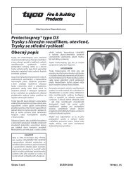
FIGURE 2A — PART 1 OF 3<br />
1-1/2 and 2 INCH (DN40 and DN50) MODEL DV-5 DELUGE VALVES<br />
— EXPLODED VIEW OF VERTICAL WET PILOT ACTUATION TRIM (52-477-X-107) —
TFP1310<br />
Page 5 of 16<br />
NO. DESCRIPTION QTY. P/N<br />
NO. DESCRIPTION QTY. P/N NO. DESCRIPTION QTY. P/N<br />
1 300 psi/ 2000 kPa<br />
10 3/4" Swing Check Valve . 1 46-049-1-005 25 1/2" 90° Elbow ......... 8 CH<br />
Water Pressure Gauge . . 2 92-343-1-005 11 3/4" Angle Valve ....... 1 46-048-1-005 26 3/4" 90° Elbow ......... 1 CH<br />
2 1/4" Gauge Test Valve .. 1 46-005-1-002 12 1-1/4" Angle Valve ...... 1 46-048-1-007 27 1/2" Tee .............. 3 CH<br />
3 Model MC-1 Manual<br />
13 Drip Funnel Connector .. 1 92-211-1-005 28 1/2" x 1/4" x 1/2" Tee .... 3 CH<br />
Control Station ......... 1 52-289-2-001 14 Drip Funnel Bracket .... 1 92-211-1-003 29 3/4" Tee .............. 1 CH<br />
4 Model AD-1 Automatic<br />
15 Drip Funnel ........... 1 92-343-1-007 30 3/4" x 1/2" x 3/4" Tee .... 2 CH<br />
Drain Valve ........... 1 52-793-2-004 16 3/32" Vent Fitting . . . . . . . 1 92-032-1-002 31 3/4" x 3/4" x 1/2" Tee .... 1 CH<br />
5 Automatic Shut-Off Valve,<br />
17 1/4" x 18" Tubing ....... 1 CH<br />
32 1-1/4" x 3/4" x 1-1/4" Tee . 1 CH<br />
Model ASV-1 . . . . . . . . . . 1 92-343-1-021 18 1/2" Tubing Connector .. 1 CH<br />
33 1/4" x Close Nipple ..... 2 CH<br />
6 Waterflow Pressure<br />
Ordered<br />
19 1/2" x 12" Tubing . . . . . . . 1 CH<br />
34 1/2" x Close Nipple ..... 2 CH<br />
Alarm Switch .......... 1 Separately 20 1/4" Plug.............. 1 CH<br />
35 1/2" x 1-1/2" Nipple ..... 13 CH<br />
7 1/2" Ball Valve ......... 2 46-050-1-004 21 3/4" Plug.............. 1 CH<br />
36 1/2" x 2-1/2" Nipple ..... 2 CH<br />
8 1/2" Spring Loaded<br />
22 1/2" Union ............ 5 CH<br />
37 1/2" x 3-1/2" Nipple ..... 1 CH<br />
Check Valve . . . . . . . . . . 1 92-322-1-002 23 3/4" Union ............ 2 CH<br />
38 1/2" x 4" Nipple ........ 1 CH<br />
9 1/2" Y-Strainer ......... 1 52-353-1-005 24 1/4" 90° Elbow ......... 1 CH<br />
39 1/2" x 4-1/2" Nipple ..... 1 CH<br />
40 1/2" x 5" Nipple ........ 1 CH<br />
41 1/2" x 5-1/2" Nipple ..... 1 CH<br />
6<br />
17<br />
42 1/2" x 7" Nipple ........ 2 CH<br />
(ORDERED<br />
43 11<br />
43 3/4" x Close Nipple ..... 3 CH<br />
SEPARATELY)<br />
31<br />
44 3/4" x 1-1/2" Nipple ..... 5 CH<br />
28<br />
44<br />
46<br />
45 3/4" x 2" Nipple ........ 1 CH<br />
16<br />
25<br />
30<br />
46 3/4" x 4-1/2" Nipple ..... 1 CH<br />
(GREEN<br />
LOCATION<br />
47 1-1/4" x 2" Nipple ....... 1 CH<br />
21<br />
TINT)<br />
FOR OPTIONAL<br />
36<br />
48<br />
1 CH<br />
26<br />
35 1-1/4" x 4" Nipple . . . . . . .<br />
ELECTRICALLY<br />
36 29<br />
SUPERVISED<br />
44<br />
23<br />
41 22 35<br />
22<br />
N.O. ALARM<br />
27<br />
4<br />
45<br />
35<br />
CONTROL VALVE<br />
44<br />
43<br />
(BVS-3/4")<br />
44<br />
23 38<br />
27<br />
35<br />
10<br />
25 42<br />
43<br />
13<br />
25<br />
25<br />
44<br />
25<br />
15<br />
1<br />
30<br />
27<br />
35<br />
35 34<br />
32<br />
35<br />
28<br />
7<br />
47 48<br />
14<br />
42<br />
40<br />
12<br />
35 3<br />
1<br />
35<br />
5 22<br />
22<br />
8<br />
20 2<br />
35<br />
NOTES:<br />
25<br />
37<br />
34<br />
9<br />
1. Wet Pilot Actuation Trim is<br />
19<br />
39<br />
35<br />
comprised of Items 1-48.<br />
18<br />
35 3" (DN80)<br />
25<br />
25<br />
2. All Fittings and Nipples are<br />
33<br />
28 GROOVE x GROOVE<br />
galvanized (Standard Order).<br />
22<br />
33<br />
MODEL DV-5<br />
3. CH: Common Hardware.<br />
24<br />
DELUGE VALVE<br />
4. See Figure 2 of TFP1305 for<br />
SHOWN<br />
35<br />
Valve Port identification.<br />
7<br />
5. Route all Tubing to Drip Funnel,<br />
Item 15.<br />
FIGURE 2A — PART 2 OF 3<br />
3 INCH (DN80) MODEL DV-5 DELUGE VALVES<br />
— EXPLODED VIEW OF VERTICAL WET PILOT ACTUATION TRIM (52-477-X-104) —
Page6of16<br />
TFP1310<br />
NO. DESCRIPTION<br />
1 300 psi/ 2000 kPa<br />
15 Drip Funnel ........... 1 92-343-1-007<br />
Water Pressure Gauge . . 2 92-343-1-005 16 3/32" Vent Fitting . . . . . . . 1 92-032-1-002<br />
2 1/4" Gauge Test Valve .. 1 46-005-1-002 17 1/4" x 24" Tubing ....... 1 CH<br />
3 Model MC-1 Manual<br />
18 1/2" Tubing Connector .. 1 CH<br />
Control Station ......... 1 52-289-2-001 19 1/2" x 24" Tubing ....... 1 CH<br />
4 Model AD-1 Automatic<br />
20 1/4" Plug.............. 1 CH<br />
Drain Valve ........... 1 52-793-2-004 21 3/4" Plug.............. 1 CH<br />
5 Automatic Shut-Off Valve,<br />
22 1/2" Union ............ 5 CH<br />
ModelASV-1 .......... 1 92-343-1-021 23 1" Union .............. 2 CH<br />
6 Waterflow Pressure<br />
Ordered<br />
24 1/4" 90° Elbow ......... 1 CH<br />
Alarm Switch .......... 1 Separately 25 1/2" 90° Elbow ......... 8 CH<br />
7 1/2" Ball Valve ......... 2 46-050-1-004 26 1" 90° Elbow .......... 1 CH<br />
8 1/2" Spring Loaded<br />
CheckValve .......... 1 92-322-1-002<br />
27<br />
28<br />
1/2" Tee .............. 3<br />
1/2" x 1/4" x 1/2" Tee .... 3<br />
CH<br />
CH<br />
9 1/2" Y-Strainer ......... 1 52-353-1-005 29 3/4" x 1/2" x 3/4" Tee .... 2 CH<br />
10 3/4" Swing Check Valve . 1 46-049-1-005 30 1" x 1" x 1/2" Tee ....... 1 CH<br />
11 1" Angle Valve ......... 1 46-048-1-006 31 1" x 3/4" x 1" Tee ....... 1 CH<br />
12 2" Angle Valve ......... 1 46-048-1-009 32 2"x1"x2" Tee ........ 1 CH<br />
13 Drip Funnel Connector .. 1 92-211-1-005 33 1/4" x Close Nipple ..... 2 CH<br />
14 Drip Funnel Bracket .... 1 92-211-1-003 34 1/2" x Close Nipple ..... 2 CH<br />
2.<br />
3.<br />
4.<br />
5.<br />
6<br />
17<br />
(ORDERED<br />
SEPARATELY)<br />
28<br />
29<br />
16<br />
LOCATION 21<br />
(GREEN<br />
FOR OPTIONAL<br />
TINT)<br />
ELECTRICALLY<br />
36<br />
SUPERVISED<br />
44<br />
N.O. ALARM<br />
45<br />
CONTROL VALVE<br />
(BVS-3/4")<br />
31<br />
35<br />
10<br />
25<br />
46<br />
29<br />
41<br />
NOTES:<br />
1. Wet Pilot Actuation Trim is<br />
comprised of Items 1-51.<br />
QTY.<br />
All Fittings and Nipples are<br />
galvanized (Standard Order).<br />
CH: Common Hardware.<br />
See Figure 2 of TFP1305 for<br />
Valve Port identification.<br />
Route all Tubing to Drip Funnel,<br />
Item 15.<br />
P/N<br />
7<br />
40<br />
20<br />
33<br />
24<br />
12<br />
NO.<br />
50<br />
1<br />
2<br />
33<br />
DESCRIPTION QTY. P/N NO. DESCRIPTION QTY.<br />
47<br />
32<br />
28<br />
23<br />
22<br />
51<br />
35<br />
47<br />
48<br />
47<br />
38<br />
23<br />
30<br />
36<br />
47<br />
47<br />
26<br />
35<br />
4" (DN100)<br />
FLANGE x FLANGE<br />
MODEL DV-5<br />
DELUGE VALVE<br />
SHOWN<br />
36<br />
27<br />
11<br />
49<br />
35<br />
25<br />
22<br />
35<br />
7<br />
25<br />
37<br />
13<br />
35 1/2" x 1-1/2" Nipple ..... 10 CH<br />
36 1/2" x 2-1/2" Nipple ..... 3 CH<br />
37 1/2" x 3" Nipple ........ 1 CH<br />
38 1/2" x 5" Nipple ........ 2 CH<br />
39 1/2" x 6" Nipple ........ 1 CH<br />
40 1/2" x 7" Nipple ........ 2 CH<br />
41 Select Nipple per Table .. 2 CH<br />
42 Select Nipple per Table .. 2 CH<br />
43 Select Nipple per Table .. 2 CH<br />
44 3/4" x 1-1/2" Nipple ..... 1 CH<br />
45 3/4" x 2" Nipple ........ 1 CH<br />
46 Select Nipple per Table .. 2 CH<br />
47 1" x Close Nipple ....... 5 CH<br />
48 1" x 3" Nipple .......... 1 CH<br />
49 Select Nipple per Table .. 2 CH<br />
50 2" x 3" Nipple .......... 1 CH<br />
51 2" x 5" Nipple .......... 1 CH<br />
25<br />
15<br />
9<br />
Nipple<br />
No.<br />
41<br />
42<br />
43<br />
46<br />
4<br />
35<br />
14<br />
25<br />
8<br />
(DN100)<br />
1/2" x 2-1/2"<br />
1/2" x 2"<br />
1/2" x 6-1/2"<br />
3/4" x 2-1/2"<br />
39<br />
43<br />
5<br />
35<br />
34<br />
22<br />
27<br />
35<br />
22<br />
38<br />
25<br />
42<br />
25<br />
40<br />
19<br />
27<br />
35<br />
3<br />
18<br />
P/N<br />
Select Appropriate Nipple Sizes<br />
per DV-5 Deluge Valve Size<br />
4" 6"<br />
8"<br />
(DN150)<br />
1/2" x 5-1/2"<br />
1/2" x 3"<br />
1/2" x 7-1/2"<br />
3/4" x 3-1/2"<br />
49 1" x 6" 1" x 9"<br />
(DN200)<br />
1/2" x 8 -1/2"<br />
1/2" x 3-1/2"<br />
1/2" x 9"<br />
3/4" x 4-1/2"<br />
1" x 12"<br />
22<br />
35<br />
25<br />
34<br />
1<br />
28<br />
FIGURE 2A — PART 3 OF 3<br />
4, 6, and 8 INCH (DN100, DN150, and DN200) MODEL DV-5 DELUGE VALVES<br />
— EXPLODED VIEW OF VERTICAL WET PILOT ACTUATION TRIM (52-477-X-101) —
TFP1310<br />
Page 7 of 16<br />
Nipple<br />
Number<br />
1<br />
2<br />
3<br />
4<br />
1-1/2" (DN40)<br />
1/2" x Close<br />
1/2" x Close<br />
1/2" x 5"<br />
3/4" x 1-1/2"<br />
2" (DN50)<br />
1/2" x 2"<br />
1/2" x Close<br />
1/2" x 5-1/2"<br />
3/4" x 1-1/2"<br />
5 3/4" x 1-1/2" 3/4" x 2-1/2"<br />
Main Drain<br />
Size<br />
Select Appropriate Nipple Sizes per DV-5 Deluge Valve Size<br />
3" (DN80)<br />
1/2" x 1-1/2"<br />
1/2" x 1-1/2"<br />
1/2" x 7"<br />
3/4" x 1-1/2"<br />
3/4" x 4-1/2"<br />
4" (DN100) 6" (DN150)<br />
1/2" x 2-1/2" 1/2" x 5-1/2"<br />
1/2" x 2"<br />
1/2" x 3"<br />
1/2" x 6-1/2" 1/2" x 7-1/2"<br />
3/4" x 2-1/2" 3/4" x 3-1/2"<br />
1" x 6" 1" x 9"<br />
3/4" NPT 3/4" NPT 1-1/4" NPT 2" NPT 2" NPT<br />
8" (DN200)<br />
1/2" x 8-1/2"<br />
1/2" x 3-1/2"<br />
1/2" x 9"<br />
3/4" x 4-1/2"<br />
1" x 12"<br />
2" NPT<br />
WATERFLOW<br />
PRESSURE ALARM<br />
SWITCH, ORDERED<br />
SEPARATELY<br />
3/4 INCH NPT<br />
CONNECTION FOR<br />
WATER MOTOR<br />
ALARM<br />
NIPPLE<br />
1<br />
NIPPLE<br />
4<br />
MAIN<br />
DRAIN VALVE<br />
(NORMALLY<br />
CLOSED)<br />
SYSTEM<br />
WATER<br />
SUPPLY<br />
PRESSURE<br />
GAUGE<br />
ALARM<br />
TEST VALVE<br />
(NORMALLY<br />
CLOSED)<br />
VENT FITTING<br />
(GREEN TINT)<br />
C<br />
B<br />
DRIP<br />
FUNNEL<br />
1-1/4 INCH NPT<br />
CONNECTION<br />
TO DRAIN<br />
A<br />
SYSTEM<br />
DRAIN VALVE<br />
(NORMALLY<br />
CLOSED)<br />
MAIN DRAIN<br />
CONNECTION<br />
(SIZED PER<br />
TABLE)<br />
AUTOMATIC<br />
DRAIN VALVE<br />
NIPPLE<br />
5<br />
DIAPHRAGM<br />
CHAMBER SUPPLY<br />
CONTROL VALVE<br />
(NORMALLY<br />
OPEN)<br />
NOTES:<br />
1. Install subassemblies in alphabetical order.<br />
2. See Figure 2 of TFP1305 for Valve Port<br />
identification.<br />
3. Route all Tubing to Drip Funnel.<br />
4. When DV-5 trips, the Automatic Shut-Off Valve<br />
shuts off the diaphragm chamber supply.<br />
5. Nipples 1-5 vary in length relative to the Model<br />
DV-5 size. Select per the table. All other nipples<br />
packed unassembled shall be installed per the<br />
appropriate trim exploded view, Figure 2A Part<br />
1, 2, or 3.<br />
4" (DN100)<br />
FLANGE x FLANGE<br />
MODEL DV-5<br />
DELUGE VALVE<br />
SHOWN<br />
1/2 INCH NPT<br />
CONNECTION FROM<br />
WATER SUPPLY<br />
1/2 INCH NPT<br />
CONNECTION<br />
FOR "WET PILOT<br />
DETECTION"<br />
FIGURE 2B<br />
1-1/2 thru 8 INCH (DN40 thru DN200) MODEL DV-5 DELUGE VALVES<br />
— OPERATIONAL COMPONENTS OF VERTICAL WET PILOT ACTUATION TRIM —<br />
D<br />
AUTOMATIC<br />
SHUT-OFF VALVE<br />
(NORMALLY<br />
OPEN)<br />
NIPPLE<br />
2<br />
NIPPLE<br />
3<br />
DIAPHRAGM<br />
CHAMBER<br />
PRESSURE<br />
GAUGE<br />
MANUAL<br />
CONTROL<br />
STATION<br />
Technical<br />
Data<br />
Approvals:<br />
UL Listed, C-UL Listed, and FM Approved.<br />
Valve Trim:<br />
The Vertical Wet Pilot Actuation Trim<br />
(Fig. 2A/2B) and Horizontal Wet Pilot<br />
Actuation Trim (Fig. 4) form a part of<br />
the laboratory listings and approvals<br />
for the DV-5 Valve and is necessary for<br />
its proper operation.<br />
Each package of trim includes the following<br />
items:<br />
• Water Supply Pressure Gauge<br />
• Diaphragm Chamber<br />
Pressure Gauge<br />
• Diaphragm Chamber Connections<br />
• Manual Control Station<br />
• Main Drain Valve<br />
• System Drain Valve<br />
• Alarm Test Valve<br />
• Automatic Drain Valve<br />
To ease field assembly of the trim arrangement,<br />
the vertical trim components<br />
are provided partially assembled<br />
as shown in Figure 2B.<br />
The trim arrangement is provided with<br />
galvanized, black, or brass nipples and<br />
fittings. The galvanized and brass trim<br />
are intended for non-corrosive or corrosive<br />
conditions, whereas the black<br />
trim is principally intended for use with<br />
AFFF systems.<br />
NOTE<br />
When the system pressure is greater<br />
than 175 psi (12,1 bar), provision is to<br />
be made to replace the standard order<br />
300 psi (20,7 bar) Water Pressure<br />
Gauges, shown in Figure 2A/2B and 4<br />
with separately ordered 600 psi (41,4<br />
bar) Water Pressure Gauges.<br />
The Wet Pilot Actuation Trim provides<br />
for connection of a detection system<br />
consisting of wet pilot line sprinklers<br />
(heat detectors) and manual control
Page8of16<br />
TFP1310<br />
Valve<br />
Size<br />
1-1/2"<br />
(DN40)<br />
2"<br />
(DN50)<br />
3"<br />
(DN80)<br />
4"<br />
(DN100)<br />
6"<br />
(DN150)<br />
8"<br />
(DN200)<br />
A<br />
7.00<br />
(177,8)<br />
7.13<br />
(181,0)<br />
7.81<br />
(198,4)<br />
10.00<br />
(254,0)<br />
11.38<br />
(289,0)<br />
12.00<br />
(304,8)<br />
B<br />
8.88<br />
(225,4)<br />
9.13<br />
(231,8)<br />
10.44<br />
(265,1)<br />
11.75<br />
(298,5)<br />
14.31<br />
(363,5)<br />
16.00<br />
(406,4)<br />
C<br />
13.19<br />
(335,0)<br />
13.19<br />
(335,0)<br />
13.19<br />
(335,0)<br />
14.31<br />
(363,5)<br />
15.31<br />
(388,9)<br />
16.25<br />
(412,8)<br />
Nominal Installation Dimensions in Inches and (mm)<br />
D E F G H J<br />
10.50<br />
(266,7)<br />
10.50<br />
(266,7)<br />
10.50<br />
(266,7)<br />
10.50<br />
(266,7)<br />
10.50<br />
(266,7)<br />
10.50<br />
(266,7)<br />
15.25<br />
(387,4)<br />
15.56<br />
(395,3)<br />
19.13<br />
(485,8)<br />
22.13<br />
(562,0)<br />
23.31<br />
(592,1)<br />
25.50<br />
(647,7)<br />
1.25<br />
(31,8)<br />
0.94<br />
(23,8)<br />
1.63<br />
(41,3)<br />
1.75<br />
(44,5)<br />
3.50<br />
(88,9)<br />
1.75<br />
(44,5)<br />
5.81<br />
(147,6)<br />
6.00<br />
(152,4)<br />
6.69<br />
(170,0)<br />
8.56<br />
(217,5)<br />
9.94<br />
(252,4)<br />
10.75<br />
(273,1)<br />
1.81<br />
(46,0)<br />
2.00<br />
(50,8)<br />
2.69<br />
(68,3)<br />
4.44<br />
(112,7)<br />
5.81<br />
(147,6)<br />
6.50<br />
(165,1)<br />
3.00<br />
(76,2)<br />
3.00<br />
(76,2)<br />
4.25<br />
(108,0)<br />
6.25<br />
(158,8)<br />
6.25<br />
(158,8)<br />
6.25<br />
(158,8)<br />
K<br />
7.00<br />
(177,8)<br />
7.00<br />
(177,8)<br />
7.00<br />
(177,8)<br />
7.13<br />
(181,0)<br />
7.13<br />
(181,0)<br />
7.13<br />
(181,0)<br />
L<br />
3.88<br />
(98,4)<br />
3.00<br />
(76,2)<br />
0.88<br />
(22,2)<br />
0.63<br />
(15,9)<br />
1.81<br />
(46,0)<br />
7.38<br />
(187,3)<br />
M<br />
8.00<br />
(204,0)<br />
8.63<br />
(220,0)<br />
12.75<br />
(324,0)<br />
15.75<br />
(400,0)<br />
18.13<br />
(460,4)<br />
22.50<br />
(570,0)<br />
* MINIMUM CLEARANCE.<br />
A<br />
* * *<br />
B<br />
1/2" NPS<br />
WET PILOT<br />
LINE<br />
C<br />
D<br />
1/2" NPS<br />
DIAPHRAGM<br />
CHAMBER SUPPLY<br />
CONNECTING TRIM<br />
(FIELD FABRICATED)<br />
L<br />
M<br />
E<br />
*<br />
F<br />
G<br />
H<br />
MAIN<br />
CONTROL<br />
VALVE<br />
2" NPS<br />
DRAIN<br />
J<br />
K<br />
1-1/4" NPS<br />
DRAIN<br />
LEFT VIEW<br />
FRONT VIEW<br />
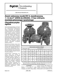
FIGURE 3<br />
1-1/2 thru 8 INCH (DN40 thru DN200) MODEL DV-5 DELUGE VALVE<br />
— VERTICAL WET PILOT ACTUATION / NOMINAL INSTALLATION DIMENSIONS —<br />
stations interconnected with minimum<br />
1/2 inch (DN15) Schedule 40 steel<br />
pipe. The pilot line is connected to the<br />
“Wet Pilot Detection” connection<br />
shown in Figure 2B. Nominal installation<br />
dimensions for the Vertical Wet<br />
Pilot Actuation Trim are shown in Figure<br />
3.<br />
Pilot sprinklers are to be minimum 5.6<br />
K-factor orifice listed or approved automatic<br />
sprinklers. Manual Control Stations<br />
are to be the Model MC-1 described<br />
in Technical Data Sheet<br />
TD1382.<br />
The maximum height of a wet pilot line<br />
above the DV-5 Valve must not exceed<br />
the limitations shown in Graph A as a<br />
function of the minimum water supply<br />
pressure to the DV-5 Valve for an<br />
equivalent length (pipe plus fittings) of<br />
the pilot line up to 500 feet to the most<br />
remote pilot sprinkler.<br />
Provision must be made for installing<br />
a 5.6 K-factor orifice, Inspector’s Test<br />
Connection at the most hydraulically<br />
demanding location of a wet pilot line<br />
(usually adjacent to the highest and<br />
most remote wet pilot sprinkler or manual<br />
control station).<br />
NOTES<br />
Wet Pilot Lines must be maintained at<br />
a minimum temperature of 40°F/4°C.<br />
At a minimum, it is recommended that<br />
internally galvanized pipe and cast<br />
iron fittings be used for wet pilot lines.
TFP1310<br />
Page 9 of 16<br />
NO. DESCRIPTION<br />
QTY.<br />
P/N<br />
1 300 psi/ 2000 kPa<br />
Water Pressure Gauge . . 2 92-343-1-005<br />
2 1/4" Gauge Test Valve .. 1 46-005-1-002<br />
3 Model MC-1 Manual<br />
Control Station ......... 1 52-289-2-001<br />
4 Model AD-1 Automatic<br />
Drain Valve ........... 1 52-793-2-004<br />
5 Automatic Shut-Off Valve,<br />
ModelASV-1 .......... 1 92-343-1-021<br />
6 Waterflow Pressure<br />
Ordered<br />
Alarm Switch .......... 1 Separately<br />
1<br />
19<br />
31<br />
23<br />
LOCATION<br />
FOR OPTIONAL<br />
ELECTRICALLY<br />
SUPERVISED<br />
N.O. ALARM<br />
CONTROL<br />
VALVE<br />
(BVS-3/4")<br />
6<br />
(ORDERED<br />
SEPARATELY)<br />
33<br />
33<br />
33<br />
33<br />
24<br />
5<br />
7<br />
21 9<br />
2<br />
8<br />
2" (DN50)<br />
GROOVE x GROOVE 32<br />
MODEL DV-5<br />
34<br />
31 DELUGE VALVE<br />
24<br />
33 SHOWN<br />
33<br />
21<br />
21<br />
36<br />
27<br />
33<br />
35<br />
20<br />
38<br />
29<br />
24<br />
42<br />
7<br />
35<br />
11<br />
33<br />
41<br />
29<br />
27<br />
43<br />
28<br />
41<br />
41<br />
10<br />
NO. DESCRIPTION<br />
QTY.<br />
P/N<br />
7 1/2" Ball Valve ......... 2 46-050-1-004<br />
8 1/2" Spring Loaded<br />
CheckValve .......... 1 92-322-1-002<br />
9 1/2" Y-Strainer ......... 1 52-353-1-005<br />
10 3/4" Swing Check Valve . 1 46-049-1-005<br />
11 3/4" Angle Valve ....... 2 46-048-1-005<br />
12 Drip Funnel Connector .. 1 92-211-1-005<br />
13 Drip Funnel Bracket .... 1 92-211-1-003<br />
14 Drip Funnel ........... 1 92-343-1-007<br />
15 3/32" Vent Fitting . . . . . . . 1 92-032-1-002<br />
16 1/4" x 18" Tubing ....... 1 CH<br />
15<br />
(GREEN<br />
TINT)<br />
22<br />
22<br />
41<br />
41<br />
35<br />
16<br />
25<br />
26<br />
37<br />
24<br />
32<br />
41<br />
41<br />
28<br />
41<br />
24<br />
44<br />
24<br />
39<br />
36<br />
30<br />
40<br />
21<br />
26<br />
35<br />
33<br />
33<br />
18<br />
26<br />
11<br />
12<br />
17<br />
4<br />
21<br />
27<br />
32<br />
24<br />
14<br />
13<br />
3<br />
1<br />
NO. DESCRIPTION<br />
17 1/2" Tubing Connector .. 1 CH<br />
18 1/2" x 12" Tubing ....... 1 CH<br />
19 1/4" Plug.............. 1 CH<br />
20 3/4" Plug.............. 1 CH<br />
21 1/2" Union ............ 5 CH<br />
22 3/4" Union ............ 2 CH<br />
23 1/4" 90° Elbow ......... 1 CH<br />
24 1/2" 90° Elbow ......... 8 CH<br />
25 3/4" 90° Elbow ......... 1 CH<br />
26 1/2" Tee .............. 3 CH<br />
27 1/2" x 1/4" x 1/2" Tee .... 3 CH<br />
28 3/4" Tee .............. 2 CH<br />
29 3/4" x 1/2" x 3/4" Tee .... 2 CH<br />
30 3/4" x 3/4" x 1/2" Tee .... 1 CH<br />
31 1/4" x Close Nipple ..... 2 CH<br />
32 1/2" x Close Nipple ..... 3 CH<br />
33 1/2" x 1-1/2" Nipple ..... 11 CH<br />
34 1/2" x 2" Nipple ........ 1 CH<br />
35 1/2" x 2-1/2" Nipple ..... 4 CH<br />
36 1/2" x 5" Nipple ........ 2 CH<br />
37 1/2" x 7" Nipple ........ 1 CH<br />
38 Select Nipple per Table .. 2 CH<br />
39 Select Nipple per Table .. 2 CH<br />
40 3/4" x Close Nipple ..... 1 CH<br />
41 3/4" x 1-1/2" Nipple ..... 8 CH<br />
42 3/4" x 2" Nipple ........ 1 CH<br />
43 3/4" x 4" Nipple ........ 1 CH<br />
44 Select Nipple per Table .. 2 CH<br />
Nipple<br />
Number<br />
38<br />
39<br />
44<br />
NOTES:<br />
1. Wet Pilot Actuation Trim is comprised of<br />
Items 1-44.<br />
2.<br />
3.<br />
4.<br />
5.<br />
Select Appropriate Nipple Sizes<br />
per DV-5 Deluge Valve Size<br />
1-1/2" (DN40)<br />
1/2" x Close<br />
1/2" x 5"<br />
3/4" x 1-1/2"<br />
QTY.<br />
P/N<br />
2" (DN50)<br />
1/2" x 2"<br />
1/2" x 5-1/2"<br />
3/4" x 2-1/2"<br />
All Fittings and Nipples are galvanized<br />
(Standard Order).<br />
CH: Common Hardware.<br />
See Figure 2 of TFP1305 for Valve Port<br />
identification.<br />
Route all Tubing to Drip Funnel, Item 14.<br />
6. Horizontal Arrangement uses only 7 out of<br />
8 of Item 24, and 10 out of 11 of Item 33.<br />
Discard unused material.<br />
FIGURE4—PART1OF3<br />
1-1/2 and 2 INCH (DN40 and DN50) MODEL DV-5 DELUGE VALVES<br />
— EXPLODED VIEW OF HORIZONTAL WET PILOT ACTUATION TRIM (52-477-X-207) —
Page 10 of 16<br />
TFP1310<br />
NO. DESCRIPTION<br />
1 300 psi/ 2000 kPa<br />
Water Pressure Gauge . . 2 92-343-1-005<br />
2 1/4" Gauge Test Valve .. 1 46-005-1-002<br />
3 Model MC-1 Manual<br />
Control Station ......... 1 52-289-2-001<br />
4 Model AD-1 Automatic<br />
Drain Valve ........... 1 52-793-2-004<br />
5 Automatic Shut-Off Valve,<br />
ModelASV-1 .......... 1 92-343-1-021<br />
20<br />
33<br />
24<br />
28<br />
1<br />
2<br />
33<br />
40<br />
LOCATION<br />
FOR OPTIONAL<br />
ELECTRICALLY<br />
SUPERVISED<br />
N.O. ALARM<br />
CONTROL<br />
VALVE<br />
(BVS-3/4")<br />
6<br />
(ORDERED<br />
SEPARATELY)<br />
21<br />
35<br />
30<br />
25<br />
35<br />
45<br />
7<br />
36<br />
12<br />
QTY.<br />
35<br />
22<br />
35<br />
P/N<br />
25<br />
7<br />
3" (DN80)<br />
GROOVE x GROOVE<br />
MODEL DV-5<br />
DELUGE VALVE<br />
SHOWN<br />
35<br />
22<br />
39<br />
47<br />
30<br />
28<br />
48<br />
32<br />
9<br />
25<br />
35<br />
44<br />
43<br />
8<br />
37<br />
10<br />
5<br />
22<br />
35<br />
23<br />
44<br />
16<br />
(GREEN<br />
TINT)<br />
23<br />
NO. DESCRIPTION<br />
6 Waterflow Pressure<br />
Ordered<br />
Alarm Switch .......... 1 Separately<br />
7 1/2" Ball Valve ......... 2 46-050-1-004<br />
8 1/2" Spring Loaded<br />
CheckValve .......... 1 92-322-1-002<br />
9 1/2" Y-Strainer ......... 1 52-353-1-005<br />
10 3/4" Swing Check Valve . 1 46-049-1-005<br />
11 3/4" Angle Valve ....... 1 46-048-1-005<br />
12 1-1/4" Angle Valve ...... 1 46-048-1-007<br />
43<br />
35<br />
35<br />
17<br />
38<br />
26<br />
25<br />
34<br />
44<br />
27<br />
44<br />
44<br />
29<br />
46<br />
42<br />
42<br />
25<br />
31<br />
43<br />
41<br />
25<br />
22<br />
36<br />
35<br />
27<br />
27<br />
11<br />
QTY.<br />
35<br />
19<br />
13<br />
35<br />
4<br />
P/N<br />
18<br />
22<br />
28<br />
34<br />
25<br />
15<br />
14<br />
3<br />
1<br />
NO. DESCRIPTION<br />
13 Drip Funnel Connector .. 1 92-211-1-005<br />
14 Drip Funnel Bracket .... 1 92-211-1-003<br />
15 Drip Funnel ........... 1 92-343-1-007<br />
16 3/32" Vent Fitting . . . . . . . 1 92-032-1-002<br />
17 1/4" x 18" Tubing ....... 1 CH<br />
18 1/2" Tubing Connector .. 1 CH<br />
19 1/2" x 12" Tubing ....... 1 CH<br />
20 1/4" Plug.............. 1 CH<br />
21 3/4" Plug.............. 1 CH<br />
22 1/2" Union ............ 5 CH<br />
23 3/4" Union ............ 2 CH<br />
24 1/4" 90° Elbow ......... 1 CH<br />
25 1/2" 90° Elbow ......... 8 CH<br />
26 3/4" 90° Elbow ......... 1 CH<br />
27 1/2" Tee .............. 3 CH<br />
28 1/2" x 1/4" x 1/2" Tee .... 3 CH<br />
29 3/4" Tee .............. 1 CH<br />
30 3/4" x 1/2" x 3/4" Tee .... 2 CH<br />
31 3/4" x 3/4" x 1/2" Tee .... 1 CH<br />
32 1-1/4" x 3/4" x 1-1/4" Tee . 1 CH<br />
33 1/4" x Close Nipple ..... 2 CH<br />
34 1/2" x Close Nipple ..... 2 CH<br />
35 1/2" x 1-1/2" Nipple ..... 13 CH<br />
36 1/2" x 2-1/2" Nipple ..... 2 CH<br />
37 1/2" x 3-1/2" Nipple ..... 1 CH<br />
38 1/2" x 4" Nipple ........ 1 CH<br />
39 1/2" x 4-1/2" Nipple ..... 1 CH<br />
40 1/2" x 5" Nipple ........ 1 CH<br />
41 1/2" x 5-1/2" Nipple ..... 1 CH<br />
42 1/2" x 7" Nipple ........ 2 CH<br />
43 3/4" x Close Nipple ..... 3 CH<br />
44 3/4" x 1-1/2" Nipple ..... 5 CH<br />
45 3/4" x 2" Nipple ........ 1 CH<br />
46 3/4" x 4-1/2" Nipple ..... 1 CH<br />
47 1-1/4" x 2" Nipple ....... 1 CH<br />
48 1-1/4" x 4" Nipple . . . . . . . 1 CH<br />
NOTES:<br />
1. Wet Pilot Actuation Trim is comprised of<br />
Items 1-48.<br />
2.<br />
3.<br />
4.<br />
5.<br />
QTY.<br />
P/N<br />
All Fittings and Nipples are galvanized<br />
(Standard Order).<br />
CH: Common Hardware.<br />
See Figure 2 of TFP1305 for Valve Port<br />
identification.<br />
Route all Tubing to Drip Funnel, Item 15.<br />
6. Horizontal Arrangement uses only 7 out of<br />
8 of Item 25, and 12 out of 13 of Item 35.<br />
Discard unused material.<br />
FIGURE4—PART2OF3<br />
3 INCH (DN80) MODEL DV-5 DELUGE VALVES<br />
— EXPLODED VIEW OF HORIZONTAL WET PILOT ACTUATION TRIM (52-477-X-204) —
TFP1310<br />
Page 11 of 16<br />
NO. DESCRIPTION<br />
20<br />
33<br />
24<br />
28<br />
1<br />
2<br />
33<br />
40<br />
LOCATION<br />
FOR OPTIONAL<br />
ELECTRICALLY<br />
SUPERVISED<br />
N.O. ALARM<br />
CONTROL<br />
VALVE<br />
(BVS-3/4")<br />
6<br />
(ORDERED<br />
SEPARATELY)<br />
21<br />
41<br />
29<br />
12<br />
25<br />
7<br />
45<br />
QTY.<br />
35<br />
7<br />
36<br />
35<br />
35<br />
22<br />
50<br />
P/N<br />
1 300 psi/ 2000 kPa<br />
Water Pressure Gauge . . 2 92-343-1-005<br />
2 1/4" Gauge Test Valve .. 1 46-005-1-002<br />
3 Model MC-1 Manual<br />
Control Station ......... 1 52-289-2-001<br />
4 Model AD-1 Automatic<br />
Drain Valve ........... 1 52-793-2-004<br />
5 Automatic Shut-Off Valve,<br />
ModelASV-1 .......... 1 92-343-1-021<br />
6 Waterflow Pressure<br />
Alarm Switch .......... 1<br />
Ordered<br />
Separately<br />
7 1/2" Ball Valve ......... 2 46-050-1-004<br />
4" (DN100)<br />
FLANGE x FLANGE<br />
MODEL DV-5<br />
DELUGE VALVE<br />
SHOWN<br />
35<br />
22<br />
38<br />
29<br />
28<br />
25<br />
32<br />
25<br />
9<br />
46<br />
47<br />
35<br />
51<br />
38<br />
8<br />
10<br />
35<br />
8 1/2" Spring Loaded<br />
CheckValve .......... 1 92-322-1-002<br />
9 1/2" Y-Strainer ......... 1 52-353-1-005<br />
10 3/4" Swing Check Valve . 1 46-049-1-005<br />
11 1" Angle Valve ......... 1 46-048-1-006<br />
12 2" Angle Valve ......... 1 46-048-1-009<br />
13 Drip Funnel Connector .. 1 92-211-1-005<br />
14 Drip Funnel Bracket .... 1 92-211-1-003<br />
15 Drip Funnel ........... 1 92-343-1-007<br />
16 3/32" Vent Fitting . . . . . . . 1 92-032-1-002<br />
17 1/4" x 24" Tubing ....... 1 CH<br />
18 1/2" Tubing Connector .. 1 CH<br />
5<br />
23<br />
44<br />
22<br />
16<br />
(GREEN<br />
TINT)<br />
23<br />
NO. DESCRIPTION<br />
47<br />
36<br />
17<br />
35<br />
35<br />
26<br />
39<br />
25<br />
34<br />
25<br />
48<br />
47<br />
31<br />
47<br />
49<br />
27<br />
47<br />
43<br />
30<br />
40<br />
25<br />
22<br />
37<br />
42<br />
27<br />
QTY.<br />
27<br />
35<br />
19<br />
13<br />
35<br />
4<br />
P/N<br />
11<br />
18<br />
22<br />
28<br />
34<br />
25<br />
15<br />
14<br />
3<br />
1<br />
NO. DESCRIPTION<br />
19 1/2" x 24" Tubing ....... 1 CH<br />
20 1/4" Plug.............. 1 CH<br />
21 3/4" Plug.............. 1 CH<br />
22 1/2" Union ............ 5 CH<br />
23 1" Union .............. 2 CH<br />
24 1/4" 90° Elbow ......... 1 CH<br />
25 1/2" 90° Elbow ......... 8 CH<br />
26 1" 90° Elbow .......... 1 CH<br />
27 1/2" Tee .............. 3 CH<br />
28<br />
29<br />
1/2" x 1/4" x 1/2" Tee .... 3<br />
3/4" x 1/2" x 3/4" Tee .... 2<br />
CH<br />
CH<br />
30 1" x 1" x 1/2" Tee ....... 1 CH<br />
31 1" x 3/4" x 1" Tee ....... 1 CH<br />
32 2" x 1" x 2" Tee ........ 1 CH<br />
33 1/4" x Close Nipple ..... 2 CH<br />
34 1/2" x Close Nipple ..... 2 CH<br />
35 1/2" x 1-1/2" Nipple ..... 10 CH<br />
36 1/2" x 2-1/2" Nipple ..... 3 CH<br />
37 1/2" x 3" Nipple ........ 1 CH<br />
38 1/2" x 5" Nipple ........ 2 CH<br />
39<br />
40<br />
1/2" x 6" Nipple ........ 1<br />
1/2" x 7" Nipple ........ 2<br />
CH<br />
CH<br />
41 Select Nipple per Table .. 2 CH<br />
42 Select Nipple per Table .. 2 CH<br />
43<br />
44<br />
Select Nipple per Table .. 2<br />
3/4" x 1-1/2" Nipple ..... 1<br />
CH<br />
CH<br />
45<br />
46<br />
3/4" x 2" Nipple ........ 1<br />
Select Nipple per Table .. 2<br />
CH<br />
CH<br />
47 1" x Close Nipple ....... 5 CH<br />
48<br />
49<br />
50<br />
1" x 3" Nipple .......... 1<br />
Select Nipple per Table .. 2<br />
2" x 3" Nipple .......... 1<br />
CH<br />
CH<br />
CH<br />
51 2" x 5" Nipple .......... 1 CH<br />
Nipple<br />
No.<br />
NOTES:<br />
1. Wet Pilot Actuation Trim is comprised of<br />
Items 1-51.<br />
2.<br />
3.<br />
4.<br />
5.<br />
41<br />
42<br />
43<br />
46<br />
(DN100)<br />
1/2" x 2-1/2"<br />
1/2" x 2"<br />
1/2" x 6-1/2"<br />
3/4" x 2-1/2"<br />
QTY.<br />
(DN150)<br />
1/2" x 5-1/2"<br />
1/2" x 3"<br />
1/2" x 7-1/2"<br />
3/4" x 3-1/2"<br />
P/N<br />
Select Appropriate Nipple Sizes<br />
per DV-5 Deluge Valve Size<br />
4" 6"<br />
8"<br />
49 1" x 6" 1" x 9"<br />
(DN200)<br />
1/2" x 8 -1/2"<br />
1/2" x 3-1/2"<br />
1/2" x 9"<br />
3/4" x 4-1/2"<br />
1" x 12"<br />
All Fittings and Nipples are galvanized<br />
(Standard Order).<br />
CH: Common Hardware.<br />
See Figure 2 of TFP1305 for Valve Port<br />
identification.<br />
Route all Tubing to Drip Funnel, Item 15.<br />
6. Horizontal Arrangement uses only 7 out of<br />
8 of Item 25, and 2 out of 3 of Item 36.<br />
Discard unused material.<br />
FIGURE4—PART3OF3<br />
4, 6 and 8 INCH (DN100, DN150, and DN200) MODEL DV-5 DELUGE VALVES<br />
— EXPLODED VIEW OF HORIZONTAL WET PILOT ACTUATION TRIM (52-477-X-201) —
Page 12 of 16<br />
TFP1310<br />
Supply<br />
Maximum Pilot Height,<br />
(2)<br />
Pressure,<br />
(1)<br />
Feet (Meters)<br />
PSI<br />
1-1/2" 2" 3"<br />
4" 6"<br />
(Bar) (DN40)<br />
(DN50)<br />
(DN80) (DN100) (DN150)<br />
20<br />
7 3<br />
7<br />
17<br />
18<br />
(1,4) (1,4) (0,9) (1,4) (5,2) (5,5)<br />
40<br />
24 19<br />
30<br />
39 38<br />
(2,8) (7,3) (5,8) (9,1) (11,9) (11,6)<br />
60<br />
46 38<br />
52<br />
54 56<br />
(4,1) (14,0) (11,6) (15,8) (16,5) (17,1)<br />
80<br />
58 54<br />
70<br />
60 70<br />
(5,5) (17,8) (16,5) (21,3) (18,3) (21,3)<br />
100<br />
78 78<br />
93<br />
78 99<br />
(6,9) (23,8) (23,8) (28,3) (23,8) (30,2)<br />
120<br />
87 87<br />
117<br />
115 130<br />
(8,3) (26,5) (26,5) (35,7) (35,10 (39,6)<br />
140<br />
105 107<br />
139<br />
142 154<br />
(9,7) (32,0) (32,6) (42,4) (43,3) (46,9)<br />
160<br />
127 123<br />
161<br />
176 161<br />
(11,0) (38,7) (37,5) (49,1) (53,6) (49,1)<br />
175<br />
134 138<br />
172<br />
171 194<br />
(12,1) (40,8) (42,1) (52,4) (52,1) (59,1)<br />
200<br />
160 160<br />
206<br />
223 216<br />
(13,8) (48,8) (48,8) (62,8) (68,0) (65,8)<br />
225<br />
185 166<br />
237<br />
233 246<br />
(15,5) (56,4) (50,6) (72,2) (71,0) (75,0)<br />
250<br />
201 199<br />
251<br />
247 275<br />
(17,2) (61,3) (60,7) (76,5) (75,3) (83,8)<br />
8"<br />
(DN200)<br />
9<br />
(2,7)<br />
38<br />
(11,6)<br />
44<br />
(13,4)<br />
58<br />
(17,8)<br />
65<br />
(19,8)<br />
96<br />
(29,3)<br />
141<br />
(43,0)<br />
170<br />
(51,8)<br />
194<br />
(50,1)<br />
206<br />
(62,8)<br />
250<br />
(76,2)<br />
257<br />
(78,3)<br />
(1)<br />
(2)<br />
(3)<br />
If supply pressure is variable, assume minimum expected value.<br />
Maximum pilot height for up to 500 feet (150 meters) of equivalent<br />
length of pilot line (pipe plus fittings).<br />
Interpolation between data points is permitted.<br />
TABLE A<br />
1-1/2 thru 8 INCH (DN40 thru DN200) MODEL DV-5 DELUGE VALVE<br />
WET PILOT DESIGN CRITERIA FOR UP TO<br />
500 FEET OF EQUIVALENT LENGTH OF PILOT LINE (PIPE PLUS FITTINGS)
TFP1310<br />
Page 13 of 16<br />
Materials Of<br />
Construction<br />
NOTES<br />
The galvanized or brass, nipples and<br />
fittings for the Valve Trim provide corrosion<br />
resistance and are intended to<br />
extend the life of the installation of the<br />
DV-5 Valve when exposed to internal<br />
and external corrosive conditions. Although<br />
these selections are intended<br />
to resist corrosion, it is recommended<br />
that the end user or other technical<br />
expert familiar with conditions at the<br />
proposed installation be consulted<br />
with respect to these selections for a<br />
given corrosive condition.<br />
Systems using a seawater or brackish<br />
water supply require special considerations<br />
in order to extend the life of<br />
the valve and trim. This type of system<br />
ideally should be configured with a primary<br />
source of clean fresh water (e.g.,<br />
a pressurized water tank) and only<br />
upon system operation is the secondary<br />
water supply (seawater or brackish<br />
water) allowed to enter the system.<br />
After the system operation, the system<br />
should then be thoroughly flushed with<br />
clean fresh water. Following this recommendation<br />
will increase the service<br />
life of the DV-5 Valve and Valve Trim.<br />
Pressure Gauges. Bronze bourdon<br />
tube with brass socket.<br />
Gauge Test Valve. Bronze body per<br />
ASTM B584.<br />
Manual Control Station. Corrosion<br />
resistant copper alloys and glass filled<br />
PTFE seals. Thermoplastic enclosure.<br />
Automatic Drain Valve. Brass body<br />
per ASTM B584, Type 440 stainless<br />
steel or brass per ASTM B134 Ball,<br />
and galvanized steel inlet.<br />
Automatic Shut-Off Valve. Brass<br />
body, cover, and center seat per UNS<br />
C36000, Type 316 stainless steel<br />
spring, and Nylon fabric reinforced,<br />
natural rubber diaphragm per ASTM<br />
D2000.<br />
Ball Valve. Corrosion resistant copper<br />
alloys and glass filled PTFE seals.<br />
Spring Loaded Check Valve. Brass<br />
body and buna-n seal.<br />
Y-Strainer. Bronze body per ASTM<br />
B584 and Type 304 stainless steel<br />
screen.<br />
Swing Check Valve. Bronze body per<br />
ASTM B584 and buna-n seal.<br />
Angle Valve. Bronze body per ASTM<br />
B584 and nitrile disc (Teflon disc for 2<br />
inch size valve).<br />
3/32" Vent Fitting. Brass per ASTM<br />
B16.<br />
Tubing Connector. Brass per ASTM<br />
B16.<br />
Tubing. Type L copper per ASTM B88.<br />
Pipe Fittings. Galvanized malleable<br />
iron per ANSI B16.3 or cast iron per<br />
ANSI B16.4; black malleable iron per<br />
ANSI B16.3 or cast iron per ANSI<br />
B16.4; or, bronze per ANSI B16.15.<br />
Pipe Nipples. Schedule 40 galvanized<br />
steel per ASTM A53 or A135; Schedule<br />
40 black steel per ASTM A53 or<br />
A135; or, Schedule 40 red brass pipe<br />
per ASTM B43.<br />
Installation<br />
NOTES<br />
Proper operation of the Model DV-5<br />
Deluge Valves depends upon their trim<br />
being installed in accordance with the<br />
instructions given in this Technical<br />
Data Sheet. Failure to follow the appropriate<br />
trim diagram may prevent<br />
the DV-5 Valve from functioning properly,<br />
as well as void listings, approvals,<br />
and the manufacturer’s warranties.<br />
The DV-5 Valve must be installed in a<br />
readily visible and accessible location.<br />
The DV-5 Valve, associated trim, and<br />
wet pilot lines must be maintained at a<br />
minimum temperature of 40°F/4°C.<br />
Heat tracing of the DV-5 Valve or its<br />
associated trim is not permitted. Heat<br />
tracing can result in the formation of<br />
hardened mineral deposits that are capable<br />
of preventing proper operation.<br />
The Model DV-5 Deluge Valve is to be<br />
installed in accordance with the following<br />
criteria:<br />
Step 1. All nipples, fittings, and devices<br />
must be clean and free of scale<br />
and burrs before installation. Use pipe<br />
thread sealant sparingly on male pipe<br />
threads only.<br />
Step 2. The DV-5 Valve must be<br />
trimmed in accordance with Figure<br />
2A/2B or 4.<br />
Step 3. Care must be taken to ensure<br />
that check valves, strainers, globe<br />
valves, etc. are installed with the flow<br />
arrows in the proper direction.<br />
Step 4. Drain tubing to the drip funnel<br />
must be installed with smooth bends<br />
that will not restrict flow.<br />
Step 5. The main drain and drip funnel<br />
drain may be interconnected provided<br />
a check valve is located at least 12<br />
inches (300 mm) below the drip funnel.<br />
Step 6. Suitable provision must be<br />
made for disposal of drain water.<br />
Drainage water must be directed such<br />
that it will not cause accidental damage<br />
to property or danger to persons.<br />
Step 7. Connect the Diaphragm<br />
Chamber Supply Control Valve to the<br />
inlet side of the system’s main control<br />
valve in order to facilitate setting of the<br />
DV-5 Valve (Ref. Figure 3).<br />
Step 8. An Inspector’s Test Connection,<br />
as described in the Technical<br />
Data section, must be provided for Wet<br />
Pilot Actuation systems.<br />
Step 9. Unused pressure alarm switch<br />
connections must be plugged.<br />
Step 10. Conduit and electrical connections<br />
are to be made in accordance
Page 14 of 16<br />
TFP1310<br />
with the requirements of the authority<br />
having jurisdiction and/or the National<br />
Electric Code.<br />
Step 11. Before a system hydrostatic<br />
test is performed in accordance with<br />
NFPA 13 system acceptance test requirements,<br />
the DV-5 Diaphragm<br />
Chamber is to be depressurized; the<br />
Automatic Drain Valve (Item 4, Fig. 2A<br />
and 4) is to be temporarily replaced<br />
with a 1/2 inch NPT plug, the 3/32 inch<br />
Vent Fitting (16 - Fig. 2A and 4) is to be<br />
temporarily replaced with a 1/4 inch<br />
NPT plug, and the Diaphragm Cover<br />
Bolts must be uniformly and securely<br />
tightened using a cross-draw<br />
sequence. After tightening, doublecheck<br />
to make certain that all of the<br />
Diaphragm Cover Bolts are securely<br />
tightened.<br />
Valve Setting<br />
Procedure<br />
Steps 1 through 11 are to be performed<br />
when initially setting the Model<br />
DV-5 Deluge Valve; after an operational<br />
test of the fire protection system;<br />
or, after system operation due to a fire.<br />
NOTE<br />
When the system is using either a<br />
seawater or brackish water supply, it is<br />
recommended that the system be thoroughly<br />
flushed with clean fresh water.<br />
Following this recommendation will increase<br />
the service life of the DV-5<br />
Valve and Trim.<br />
Step 1. Close the Main Control Valve.<br />
Step 2. Close the Diaphragm Chamber<br />
Supply Control Valve.<br />
Step 3. Open the Main Drain Valve,<br />
System Drain Valve, and all auxiliary<br />
drains in the system. Close the System<br />
Drain Valve and auxiliary drain valves<br />
after water ceases to discharge. Leave<br />
the Main Drain Valve open.<br />
Step 4. Depress the plunger of the<br />
Automatic Drain Valve to verify that it<br />
is open and that the DV-5 Valve is<br />
completely drained.<br />
Step 5. Clean the Strainer in the Diaphragm<br />
Chamber Supply connection<br />
by removing the clean-out plug and<br />
strainer basket. The Strainer may be<br />
flushed out by momentarily opening<br />
the Diaphragm Chamber Supply Control<br />
Valve.<br />
Step 6. Reset the actuation system.<br />
Manual Actuation — Push the operating<br />
lever up; however, do not close the<br />
hinged cover at this time.<br />
Wet Pilot Actuation — Replace operated<br />
pilot sprinklers and/or reset the<br />
manual control stations.<br />
NOTE<br />
In order to prevent the possibility of a<br />
subsequent operation of an overheated<br />
solder type pilot sprinkler, any<br />
solder type pilot sprinklers that were<br />
possibly exposed to a temperature<br />
greater than their maximum rated ambient<br />
must be replaced.<br />
Step 7. Open the Diaphragm Chamber<br />
Supply Control Valve and allow time for<br />
full pressure to build up in the Diaphragm<br />
Chamber.<br />
Step 8. Operate (open) the Manual<br />
Control Station to vent trapped air from<br />
the Diaphragm Chamber. If necessary,<br />
first open the hinged cover, and then<br />
fully pull down on the operating lever.<br />
SLOWLY close the operating lever, by<br />
pushing it up, after aerated water<br />
ceases to discharge from the Manual<br />
Control Station drain tubing. Close the<br />
hinged cover and insert a new break<br />
rod in the small hole through the top of<br />
the enclosing box.<br />
Crack open the Inspector’s Test Connection<br />
and any other vent valves on<br />
the wet pilot line to relieve trapped air.<br />
After the discharge of air has stopped,<br />
close the vent valves and the Inspector’s<br />
Test Connection.<br />
Step 9. Inspect the drain connection<br />
from the Manual Control Station. Any<br />
leaks must be corrected before proceeding<br />
to the next step.<br />
Step 10. Verify the ability for the DV-5<br />
Diaphragm to hold pressure as follows:<br />
With the diaphragm chamber pressurized<br />
per Step 8, temporarily close the<br />
Diaphragm Chamber Supply Control<br />
Valve, and monitor the Diaphragm<br />
Chamber Pressure Gauge for a drop in<br />
pressure.<br />
If a drop in pressure is noted, the DV-5<br />
Diaphragm is to be replaced and/or<br />
any leaks must be corrected before<br />
proceeding to the next step.<br />
If the Diaphragm Chamber Pressure<br />
Gauge does not indicate a drop in<br />
pressure, re-open the Diaphragm<br />
Chamber Supply Control Valve and<br />
proceed to the next step.<br />
Step 11. Slowly open the Main Control<br />
Valve. Close the Main Drain Valve as<br />
soon as water discharges from the<br />
drain connection. Observe the Automatic<br />
Drain Valve for leaks. If there are<br />
leaks, determine/correct the cause of<br />
the leakage problem. If there are no<br />
leaks, the DV-5 Valve is ready to be<br />
placed in service and the Main Control<br />
Valve must then be fully opened.<br />
NOTES<br />
When the Main Control Valve is<br />
opened, the pressure on the Diaphragm<br />
Chamber may increase. This<br />
increase in pressure is normal, and if<br />
the pressure is greater than 250 psi<br />
(17,2bar),thepressureistoberelieved<br />
by partially and temporarily<br />
opening the Manual Control Station;<br />
however, do not allow the pressure as<br />
indicated on the Diaphragm Chamber<br />
Pressure Gauge to drop below the<br />
supply pressure shown on the Water<br />
Supply Pressure Gauge, since this action<br />
may result in tripping of the DV-5<br />
Valve.<br />
After setting a fire protection system,<br />
notify the proper authorities and advise<br />
those responsible for monitoring<br />
proprietary and/or central station<br />
alarms.
TFP1310<br />
Page 15 of 16<br />
Care and<br />
Maintenance<br />
The following procedures and inspections<br />
must be performed as indicated,<br />
in addition to any specific requirements<br />
of the NFPA, and any impairment<br />
must be immediately corrected.<br />
The owner is responsible for the inspection,<br />
testing, and maintenance of<br />
their fire protection system and devices<br />
in compliance with this document,<br />
as well as with the applicable<br />
standards of the National <strong>Fire</strong> Protection<br />
Association (e.g., NFPA 25), in<br />
addition to the standards of any<br />
authority having jurisdiction. The installing<br />
contractor or product manufacturer<br />
should be contacted relative to<br />
any questions.<br />
It is recommended that automatic<br />
sprinkler systems be inspected,<br />
tested, and maintained by a qualified<br />
Inspection Service in accordance with<br />
local requirements and/or national<br />
codes.<br />
NOTES<br />
Some of the procedures outlined in<br />
this section will result in operation of<br />
the associated alarms. Consequently,<br />
notification must first be given to the<br />
owner and the fire department, central<br />
station, or other signal station to which<br />
the alarms are connected.<br />
When the system is using either a<br />
seawater or brackish water supply, internal<br />
and external inspection of the<br />
DV-5 Valve and Trim is essential.<br />
Parts showing any signs of corrosion<br />
must be replaced to ensure the integrity<br />
of the system.<br />
Before closing a fire protection system<br />
main control valve for maintenance<br />
work on the fire protection system that<br />
it controls, permission to shut down the<br />
affected fire protection systems must<br />
first be obtained from the proper<br />
authorities and all personnel who may<br />
be affected by this action must be notified.<br />
Reset the Model DV-5 Deluge<br />
Valve in accordance with the Valve<br />
Setting Procedure section.<br />
Annual Operation Test Procedure<br />
Proper operation of the DV-5 Valve<br />
(i.e., opening of the DV-5 Valve as during<br />
a fire condition) must be verified at<br />
least once a year as follows:<br />
Step 1. If water must be prevented<br />
from flowing beyond the riser, perform<br />
the following steps.<br />
• Close the Main Control Valve. Open<br />
the Main Drain Valve.<br />
• Open the Main Control Valve one<br />
turn beyond the position at which<br />
water just begins to flow from the<br />
Main Drain Valve.<br />
• Close the Main Drain Valve.<br />
Step 2. Open the Inspector’s Test Connection.<br />
NOTE<br />
Be prepared to quickly perform Steps<br />
3, 4, and 5, if water must be prevented<br />
from flowing beyond the riser.<br />
Step 3. Verify that the DV-5 Valve has<br />
tripped, as indicated by the flow of<br />
water into the system.<br />
Step 4. Close the system’s Main Control<br />
Valve.<br />
Step 5. Close the Diaphragm Chamber<br />
Supply Control Valve.<br />
Step 6. Reset the DV-5 Deluge Valve<br />
in accordance with the Valve Setting<br />
Procedure.<br />
Quarterly Waterflow Alarm Test<br />
Procedure<br />
Testing of the system waterflow alarms<br />
must be performed quarterly. To test<br />
the waterflow alarm, open the Alarm<br />
Test Valve, which will allow a flow of<br />
water to the Pressure Alarm Switch<br />
and/or Water Motor Alarm. Upon satisfactory<br />
completion of the test, close<br />
the Alarm Test Valve.<br />
Limited<br />
Warranty<br />
<strong>Products</strong> manufactured by <strong>Tyco</strong> <strong>Fire</strong><br />
<strong>Products</strong> are warranted solely to the<br />
original Buyer for ten (10) years<br />
against defects in material and workmanship<br />
when paid for and properly<br />
installed and maintained under normal<br />
use and service. This warranty will expire<br />
ten (10) years from date of shipment<br />
by <strong>Tyco</strong> <strong>Fire</strong> <strong>Products</strong>. No warranty<br />
is given for products or<br />
components manufactured by companies<br />
not affiliated by ownership with<br />
<strong>Tyco</strong> <strong>Fire</strong> <strong>Products</strong> or for products and<br />
components which have been subject<br />
to misuse, improper installation, corrosion,<br />
or which have not been installed,<br />
maintained, modified or repaired in accordance<br />
with applicable Standards of<br />
the National <strong>Fire</strong> Protection Association,<br />
and/or the standards of any other<br />
Authorities Having Jurisdiction. Materials<br />
found by <strong>Tyco</strong> <strong>Fire</strong> <strong>Products</strong> to be<br />
defective shall be either repaired or<br />
replaced, at <strong>Tyco</strong> <strong>Fire</strong> <strong>Products</strong>’ sole<br />
option. <strong>Tyco</strong> <strong>Fire</strong> <strong>Products</strong> neither assumes,<br />
nor authorizes any person to<br />
assume for it, any other obligation in<br />
connection with the sale of products or<br />
parts of products. <strong>Tyco</strong> <strong>Fire</strong> <strong>Products</strong><br />
shall not be responsible for sprinkler<br />
system design errors or inaccurate or<br />
incomplete information supplied by<br />
Buyer or Buyer’s representatives.<br />
IN NO EVENT SHALL TYCO FIRE<br />
PRODUCTS BE LIABLE, IN CON-<br />
TRACT, TORT, STRICT LIABILITY OR<br />
UNDER ANY OTHER LEGAL THE-<br />
ORY, FOR INCIDENTAL, INDIRECT,<br />
SPECIAL OR CONSEQUENTIAL<br />
DAMAGES, INCLUDING BUT NOT<br />
LIMITED TO LABOR CHARGES, RE-<br />
GARDLESS OF WHETHER TYCO<br />
FIRE PRODUCTS WAS INFORMED<br />
ABOUT THE POSSIBILITY OF SUCH<br />
DAMAGES, AND IN NO EVENT<br />
SHALL TYCO FIRE PRODUCTS’ LI-<br />
ABILITY EXCEED AN AMOUNT<br />
EQUAL TO THE SALES PRICE.<br />
THE FOREGOING WARRANTY IS<br />
MADE IN LIEU OF ANY AND ALL<br />
OTHER WARRANTIES EXPRESS OR<br />
IMPLIED,INCLUDING WARRANTIES<br />
OF MERCHANTABILITY AND FIT-<br />
NESS FOR A PARTICULAR PUR-<br />
POSE.
Page 16 of 16<br />
TFP1310<br />
Ordering<br />
Procedure<br />
NOTE<br />
Part Numbers for factory pre-trimmed<br />
Model DV-5 Valves are provided in the<br />
Price Book.<br />
DV-5 Semi-Preassembled Vertical<br />
Wet Pilot Actuation Trim :<br />
Specify: (specify size and finish — galvanized<br />
is standard) Semi-Preassembled<br />
Vertical Wet Pilot Actuation Trim<br />
for Model DV-5 Deluge Valves, P/N<br />
(specify).<br />
1-1/2 & 2 Inch Galvanized . P/N 52-477-2-107<br />
1-1/2 & 2 Inch Black . . . . . P/N 52-477-1-107<br />
1-1/2 & 2 Inch Brass . . . . . P/N 52-477-3-107<br />
3 Inch Galvanized. . . . . . . . P/N 52-477-2-104<br />
3 Inch Black . . . . . . . . . . . . P/N 52-477-1-104<br />
3 Inch Brass . . . . . . . . . . . . P/N 52-477-3-104<br />
Accessories:<br />
Refer to the Technical Data Sheets for<br />
the following, as applicable, for details<br />
and additional accessories:<br />
600 PSI Water<br />
Pressure Gauge . . . . . . P/N 92-343-1-004<br />
Model PS10-2A<br />
Potter Electric<br />
Waterflow<br />
Pressure<br />
Alarm Switch . . . . . . . . P/N 2571<br />
Model WMA-1 Water<br />
Motor Alarm . . . . . . . . . P/N 52-630-1-001<br />
Model MC-1<br />
Manual Control<br />
Stations with<br />
galvanized<br />
connections for<br />
remote wet pilot<br />
actuation. . . . . . . . . . . . P/N 52-289-2-001<br />
Replacement Trim Parts :<br />
Specify: (description) for use with<br />
Model DV-5 Deluge Valve, P/N (see<br />
Figure 2A or 4).<br />
4, 6 & 8 Inch Galvanized . . P/N 52-477-2-101<br />
4, 6 & 8 Inch Black . . . . . . . P/N 52-477-1-101<br />
4, 6 & 8 Inch Brass. . . . . . . P/N 52-477-3-101<br />
DV-5 Unassembled Wet Pilot Actuation<br />
Trim for Vertical or Horizontal<br />
Installation:<br />
Specify: (specify size and finish — galvanized<br />
is standard) Unassembled<br />
Wet Pilot Actuation Trim for vertical or<br />
horizontal installation of Model DV-5<br />
Deluge Valves, P/N (specify).<br />
1-1/2 & 2 Inch Galvanized . P/N 52-477-2-207<br />
1-1/2 & 2 Inch Black . . . . . . P/N 52-477-1-207<br />
1-1/2 & 2 Inch Brass. . . . . . P/N 52-477-3-207<br />
3 Inch Galvanized. . . . . . . . P/N 52-477-2-204<br />
3 Inch Black . . . . . . . . . . . . P/N 52-477-1-204<br />
3 Inch Brass . . . . . . . . . . . . P/N 52-477-3-204<br />
4, 6 & 8 Inch Galvanized . . P/N 52-477-2-201<br />
4, 6 & 8 Inch Black . . . . . . . P/N 52-477-1-201<br />
4, 6 & 8 Inch Brass. . . . . . . P/N 52-477-3-201<br />
TYCO FIRE PRODUCTS, 451 North Cannon Avenue, Lansdale, Pennsylvania 19446