Ramallah Recreational Complex - UNDP
Ramallah Recreational Complex - UNDP
Ramallah Recreational Complex - UNDP

You also want an ePaper? Increase the reach of your titles
YUMPU automatically turns print PDFs into web optimized ePapers that Google loves.
Technical Specifications Sports center -<strong>Ramallah</strong> FIRST OPTION<br />
<strong>Ramallah</strong> Municipality<br />
Project Name:<br />
<strong>Ramallah</strong> <strong>Recreational</strong> <strong>Complex</strong><br />
Phase 1<br />
Sports Center<br />
<strong>Ramallah</strong>, Palestine<br />
Volume VI<br />
GENERAL AND PARTICULAR SPECIFICATIONS<br />
A- Architectural & Structural<br />
SPORT HALL<br />
Funded by: IBSA<br />
INDIA BRAZIL SOUTH AFRICA<br />
Through: United Nations Development Programme<br />
Programme Assistance to the Palestinian people<br />
Designed by<br />
First Option- Amara<br />
Architects, Engineers & Construction Managements<br />
2009<br />
1
Technical Specifications Sports Center -<strong>Ramallah</strong> FIRST OPTION<br />
1 Scope<br />
SECTION: 24<br />
DRAINAGE<br />
This Specification deals with the installation of the materials, fittings and equipment, the design and<br />
performance, the workmanship and the testing and commissioning of the below ground drainage.<br />
This Specification is in addition to and will be read in conjunction with the Contract Drawings and<br />
relevant parts of the Contract Documents.<br />
2 General<br />
Works shall be constructed in accordance with BS CP 301 : 1971 Building Drainage. The Contractor<br />
shall notify the Engineer of discrepancies between BS CP 301 and the working drawings and<br />
specifications.<br />
Pipes and fittings shall be jointed and laid in accordance with the manufacturer's recommendations.<br />
The Contractor shall notify the Engineer of discrepancies between the manufacturer's recommendations<br />
and the design.<br />
Unless otherwise stated, the provisions of the latest revised additions of relevant British Standards and<br />
Codes of Practice shall be held to be incorporated in the specification of materials and workmanship.<br />
Drains shall be accurately laid, true to line and grade from point to point. Manholes shall be provided<br />
at changes of direction or gradient and at points of connection. Drain runs between manholes should be<br />
absolutely straight. Lines and falls shall be accurately set as shown on Drawings or as directed on Site.<br />
Pipe work materials shall be as stated in the Particular Conditions or on the Drawings.<br />
The Contractor shall perform all necessary excavation for drains, manholes, septic tanks, soak ways etc.<br />
, uphold sides , level or grade bottoms , return fill and ram and remove surplus spoil as directed .<br />
The system shall be maintained in accordance with Clause 6 of CP 301 .<br />
3 Pipe work<br />
Excavation of any section of the work shall not start until a complete set of the pipes and components<br />
for that section is available.<br />
The trench shall be as narrow as practicable but not less than the pipe diameter plus 300mm from each<br />
side to permit adequate compaction of side fill. Adequate working space shall be left for pipe jointers<br />
and joint holes shall be formed where necessary.<br />
The trench sides shall be kept vertical unless the approved use of a batter is unavoidable. In the latter<br />
case the sides of the trench shall be kept vertical up to 300mm above the top of the pipe. If over width<br />
excavation occurs at or below this level the trench shall be reformed using concrete to 300mm above the<br />
level of the top of the pipe or the Engineer's approval shall be obtained for the proposed bedding for the<br />
wider trench condition.<br />
Bedding material shall be<br />
(a) Local korkar .<br />
(b) Sand to BS 882 Zones 1 - 4 .<br />
Pipes and fittings shall be inspected before fixing, and defective items shall be rejected.<br />
Pipes shall be laid with the socket ends against the flow and shall rest on a solid and even bearing for<br />
the full length of the barrel.<br />
Trenches shall be back-filled only after drains have been tested to the satisfaction of the Engineer.<br />
98
Technical Specifications Sports Center -<strong>Ramallah</strong> FIRST OPTION<br />
Flexible pipes including pitch fiber pipes, PVC pipes, steel pipes and tubes and ductile iron pipes shall<br />
be laid on a granular or sand bed. The trench shall be excavated below the invert level of the pipe to<br />
depth that will allow a minimum thickness of 200mm of Sand as bedding material, which shall extend<br />
to the full width of the trench.<br />
In rocky ground a minimum of 200mm of granular or sand bed shall be used.<br />
The bedding material shall be well tamped down on the trench bottom, which shall be free from hard,<br />
or soft spots.<br />
The finished bottom shall be true to line and gradient.<br />
Rigid pipes including vitrified clayware, asbestos cement pipes, grey iron pipes and concrete pipes<br />
shall either be laid on a granular or sand bed or on a concrete base in the trench bottom. The type of<br />
base provided shall depend on the nature of the trench formation and the presence of ground water.<br />
Where the nature of the ground is such as to allow the trench formation to be trimmed to provide a<br />
uniform and solid bearing, pipes shall be laid upon the formation. Socket and joint holes shall be as<br />
short as practicable and shall be scraped or cut into the formation.<br />
Where because of the nature of the ground or the presence of ground water pipes cannot be laid directly<br />
on the trench formation, the trench shall be excavated below the invert level of the pipe to a depth to<br />
allow a minimum thickness of 200mm of granular bedding material, which shall extend the full width<br />
of the trench. The bedding material, trench, etc., shall be as for flexible pipes.<br />
Where pipes are to be laid with a concrete bed, bed and haunch or surrounds, the trench bottom shall be<br />
prepared as for the laying of pipes on a granular bed but with a layer of concrete at least 50mm thick.<br />
The pipes shall be supported clear of the trench bottom by blocks or cradles placed under the pipe and<br />
immediately behind each socket for short small pipes with a second block near the spigot end for long<br />
or large pipes.<br />
The support should yield under load sufficiently to permit the barrel of the pipe to rest uniformly on its<br />
bed after the normal setting shrinkage of the concrete has occurred. The clearance under the barrel<br />
before placing the concrete should be not less than 100mm. The concrete bed or haunch should extend<br />
to 150mm on each side of the pipe.<br />
Concrete shall not be laid until the drain has been approved by the Engineer.<br />
Where rigid pipes with flexible joints are employed with a concrete bed, haunch or surround a simple<br />
constructional flexible joint shall be provided in the concrete and at the face of a pipe joint at intervals of<br />
not more than 5 meters to reduce the natural rigidity of the concrete.<br />
The first 300mm of filling above the top of pipes and the filling around the pipes shall be placed by<br />
hand over the pipe and compacted by hand in finished layers of 150mm to a maximum of 300mm and<br />
shall be selected material, well watered and carefully rammed around the pipes .The material shall be<br />
distributed equally to both sides of the pipe to buttress it to the sides of the trench. Subsequent filling<br />
shall be placed, rammed and watered if necessary in 300mm thick layers. Drains shall be kept free from<br />
earth, sand, surplus mortar and other obstructions during laying. Adequate cover shall be provided<br />
before using power compactors or heavy rollers.<br />
Vitrified clay pipes and concrete pipes with more than 4.25 m of earth cover shall be laid on a 150mm<br />
thick bench of concrete and be haunched with concrete 150mm thick to at least the horizontal diameter<br />
of the pipe and above that level splayed tangentially to the extrados.<br />
Where vitrified clay pipes and concrete pipes with more than 6 m of earth cover are used or where the<br />
pipes are laid in a heading or the cover is less than 1.2m if the pipes are laid in roads or 0.90 m<br />
elsewhere, the pipe shall be completely surrounded with concrete to a thickness of not less than 150mm.<br />
The width of concrete beds shall be 150mm greater than the external diameter of the pipe on both sides.<br />
99
Technical Specifications Sports Center -<strong>Ramallah</strong> FIRST OPTION<br />
Where drains run beneath buildings they shall be constructed of cast iron pipes and shall be encased in<br />
concrete on bottom, top and both sides to a thickness of 150mm greater than the external diameter of the<br />
pipe and adequate flexibility in the pipeline shall be allowed.<br />
The Engineer shall be consulted if pipes are to be laid with less than 600mm of cover or within 150mm<br />
of the underside of a concrete slab.<br />
The head of every drainage system shall be ventilated and such ventilating pipes shall, where possible,<br />
be fixed against the outside face of an external wall unless otherwise shown on the Drawings and<br />
carried up to a height of 900mm above that part of the structure immediately adjacent to it. The<br />
ventilating pipe shall be fitted with a galvanized or copper wire balloon at the top.<br />
Except where branches or other fittings occur, the top length of each ventilating stack shall consist of a<br />
complete length of pipe which shall be anchored 1.20 m from the top by means of wrought steel strap<br />
fixed as described elsewhere and painted to match the pipe. Any short length required to make up the<br />
length of the stack shall be fitted immediately below the top length.<br />
4 UPVC Pipes and Fittings<br />
UPVC pipes and fittings shall comply with BS 4660 .<br />
All pipes and fittings on all soil, waste and vent pipes shall be in Unplasticised Polyvinyle Chloride,<br />
with solvent weld cement joints, to pipes and fittings.<br />
All branch waste and vent pipes from baseness and sinks to stacks, floor gullies, collection boxes and<br />
manholes shall be in modified UPVC with seal ring joints suitable to receive high temperature water<br />
discharge.<br />
Fittings and coupling for use with UPVC pipes shall be jointed with solvent cement in accordance with<br />
manufacturer recommendations.<br />
Fittings and coupling for use with UPVC pipes on movement joints shall be jointed with an incorporate<br />
synthetic rubber rings in accordance with the manufacturer recommendations.<br />
Slip on cover plates shall be provided as a finish to pipe work, up to and including 50mm diameter,<br />
emerging from a wall in occupied areas other than service voids. Samples shall be first submitted to the<br />
Engineer for approval.<br />
On pipe work up to and including 50mm diameter union type fittings shall be provided to make up to<br />
outlets of basin, bath and sink wastes.<br />
Access plates shall be fitted at the roof of each vertical stack at changes, to enable the complete disposal<br />
system to be internally cleaned and rodded.<br />
Soil, waste and vent stacks above their highest branches shall be continued upwords, at their full<br />
diameter, above roof level.<br />
5 Safety<br />
The Contractor shall provide, maintain and uphold safety measures adequate for the particular hazards<br />
of drainage works for all his employees. All safety measures taken by the Contractor should be<br />
approved by the Engineer.<br />
Such approval will not affect the full responsibility of the contractor toward the safety of all his<br />
employees, the supervision staff and any other third party existing on site.<br />
The Contractor shall ensure that all timbering, shuttering , staging, strutting , ladders etc. , used in<br />
drain trenches and pits are adequate for the duty involved .<br />
6 Manholes<br />
Manhole dimensions shall be as shown on Drawings.<br />
Manholes shall be constructed from approved precast concrete rings.<br />
100
Technical Specifications Sports Center -<strong>Ramallah</strong> FIRST OPTION<br />
Manholes, chambers, Septic tanks, disintegration and settling tanks and percolating pits shall be<br />
constructed in the positions and to the dimensions shown on the Drawings or as directed by the<br />
Engineer. The method of execution of all work in connection with these shall be as elsewhere described<br />
in the appropriate trades.<br />
Manhole base slabs shall be according to drawings, and at least 150mm thick grade (A) concrete or as<br />
directed and approved by the Engineer.<br />
Manhole cover slabs shall be a minimum of 150mm thick suitably reinforced grade (A) concrete, where<br />
also approved precast covers can be used.<br />
Precast concrete manholes shall comply with BS 556 .<br />
Manhole sections shall be jointed using a cement and sand mortar, 1: 2, and proprietary bituminous or<br />
resin fillers. Where flexible fillers are used their shape, thickness and location in the joint shall be in<br />
accordance with the manufacturer's recommendations. The remainder of the joint shall be filled with a<br />
cement and sand mortar 1: 2, to prevent settlement of the sections with possible point contact and<br />
subsequent spalling of the concrete joint.<br />
Precast concrete manholes used below water table level shall be surrounded with a minimum thickness<br />
of 150mm concrete which shall be not less than a 1:2:4 mix.<br />
Sulphate resisting cements shall be used in concrete and mortar, or accepted epoxy paint should be<br />
made for all concrete and mortars facing the wastewater.<br />
Cast iron manhole covers and frames shall comply with BS 497 except that the bituminous based<br />
protective coating shall not flow or chip when exposed to temperatures in the range of 0 O C to 76.7 O C .<br />
Manholes exceeding 1.00 meter deep internally shall have a minimum internal diameter of 80 cm.<br />
Where required the channels in manhole bottoms shall be constructed of glazed earthenware channels<br />
jointed in a similar manner to the pipes. Alternatively when so described the channels shall be formed<br />
in fine concrete finished smooth. The channels shall be semi circular in section and the concrete shall<br />
then be carried up vertically for a distance of 80mm at each side and sloped back at a minimum fall of 1<br />
: 10 .<br />
The benching shall be of fine concrete and shall be rendered over in cement and sand (1: 3) mix. Pipes<br />
entering manholes shall not project beyond the face of the internal rendering. The invert of the pipes<br />
and the channels shall be continuous. All benching surfaces should be painted by approved epoxy<br />
paint.<br />
Covers and frames shall comply with the following:<br />
GRADE A: Heavy duty covers suitable for heavy fast moving wheeled traffic ( 25 tons ) .<br />
GRADE B: Medium duty covers suitable where heavy commercial vehicles would be excepted ( 8 tons)<br />
GRADE C: Light duty covers suitable for pedestrian traffic only (5 tons).<br />
Manhole covers situated inside buildings or on verandahs shall be as follows:<br />
Either (a) Double seal type cover and frame<br />
or (b) Frame with ground - fit air tight cover manufactured for use inside buildings .<br />
Manhole frames shall be bedded and pointed with cement and sand mortar and the rebates sealed with<br />
manhole grease.<br />
Step irons shall be located and comply with BS CP 301 , Clause 3.12.5.1.<br />
Channels and benching shall comply with BS CP 301 .<br />
Where cast iron inspection chambers are shown on the Drawings these are to comply with BS 1130<br />
using caulked joints and gasket sealed covers set in concrete block manholes benched to top of cover<br />
level. The manhole cover required can be single seal in lieu of double seal .<br />
101
Technical Specifications Sports Center -<strong>Ramallah</strong> FIRST OPTION<br />
7 Septic Tanks<br />
Septic tanks shall be sized and constructed as shown on the Engineer's Drawings and shall be<br />
constructed as stated in BS CP 302 unless otherwise stated.<br />
Septic tanks shall be constructed with concrete floors and walls of block work or concrete.<br />
External Walls of septic tanks shall be at least 300mm thick.<br />
Where indicted on the drawings the Contractor shall provide an intercepting trap with cleaning arm<br />
and lever-locking stopper to be set in cement mortar in the intercepting manhole adjacent to the septic<br />
tank or inside the site boundary in the case of main drainage. The normal drop from inlet to outlet of<br />
trap shall be preserved. A fresh air inlet shall be taken to the intercepting manhole with 100mm cast iron<br />
drainpipes with an easy bend to a point just below ground level.<br />
Septic tanks shall meet the requirements of the local Authority.<br />
8 Soak ways<br />
Soakaways shall be constructed in one of the following ways:<br />
(a) Precast concrete rings to BS 556 .<br />
(b) 200mm (min) cast in situ concrete.<br />
Cover and base slabs shall be at least 150mm thick Grade (A) reinforced concrete, or precast covers<br />
according to Specification and as directed and approved by the Engineer.<br />
Removable covers shall be as described for manhole covers.<br />
Soak ways shall be of the sizes and in the positions shown on the Drawings or as directed on site by the<br />
Engineer.<br />
Soak ways constructed in cast in site concrete shall have walls of at least 200mm thicknesses.<br />
Soak ways shall meet the requirements of the Local Authority.<br />
9 Connections To Existing Manholes And Drains<br />
When work is being undertaken on existing drains and manholes including the construction of new<br />
manholes, building in pipes, cutting through manhole walls, cutting out and reforming benching,<br />
completing pipe entries and making good the Contractor shall keep existing drains open to flow and<br />
reasonably free form debris at all times during the progress of works .<br />
On completion all work shall be in a watertight condition.<br />
10 Cleaning, Protection and Testing Of Drains<br />
The Contractor shall remove all silt and foreign matter from drains and manholes and leave the whole<br />
in a clean and workable condition.<br />
In the event of delay between the laying of a drain and the placing of the first 300mm of back filling<br />
over the top of the pipe, precautions shall be taken to protect the pipes from damage arising from<br />
differential exposure to sun or wind.<br />
Lengths of drain, manholes and inspection chambers shall be capable of withstanding the test. The test<br />
shall be applied after laying and before back filling or placing concrete surround and bedding concrete.<br />
102
Technical Specifications Sports Center -<strong>Ramallah</strong> FIRST OPTION<br />
Leakage of the section under test, including sweating, which causes a drop in the test water level shall<br />
be noted and the defective part of the work shall be rectified on the Contractor's own expenses.<br />
The test shall be repeated after back filling and any faults in the bedding or support of the pipe,<br />
inadequacies in design or accidental damage during, or subsequent to, back filling, shall be noted and<br />
the defective part of the work shall be rectified on the Contractor's own expenses.<br />
Whenever possible testing shall be carried out from manhole to manhole.<br />
Testing shall not be started until at least 48 hours after completion of the last joint.<br />
Tests before back filling:<br />
(1The section shall be filled with water and after about one hour test readings shall be taken.<br />
(2) A test pressure of 1. 2m head of water shall be applied at the high end of the section (but not<br />
Than 2.4m at the low end) . Steeply graded mains shall be tested in sections.<br />
(3) The loss of water over a period of 30 minutes shall be measured by adding water from a measuring<br />
Vessel at regular intervals of 10 minutes and noting the quantity required maintaining the original<br />
Water level in the standpipe.<br />
(4)The average quantity of water added shall not exceed 0.06 liters per hour per 100 linear meters per<br />
millimeter of nominal bore of the drain.<br />
(5) For sections of drain where the highest point is more than 1.2m below the water table the<br />
Following infiltration test shall be undertaken.<br />
(A) Inlets to the system shall be closed. Visual inspection at manholes or inspection chambers will<br />
Reveal any flow the cause of which shall be investigated and the faults rectified.<br />
(B) Tests for line, level and freedom from obstruction shall be applied by means of a mirror at one end<br />
Of the drain and a lamp at the other.<br />
(C) Final test:<br />
The water test shall be repeated in accordance with the requirements of the Local Authority or the<br />
Engineer.<br />
103
Technical Specifications Sports Center -<strong>Ramallah</strong> FIRST OPTION<br />
SECTION : 25<br />
ASPHALT WORKS<br />
1 GENERAL<br />
The Contractor shall construct the area to be paved in accordance with the applicable specifications<br />
stipulated herein after, in conformity with the alignment, dimensions, and typical sections shown on the<br />
Drawings, or as directed by the Engineer.<br />
2 TYPE OF WORK<br />
For the purpose of these specifications, the following type of asphalt works is designated:<br />
- Preparing and leveling of existing base - coarse.<br />
- Compacting of existing base - coarse.<br />
- Prime coat.<br />
- Single asphalt surface layer.<br />
3 BASE - COARSE<br />
General<br />
The Contractor shall provide only an aggregate material for the base-coarse consisting of hard, durable,<br />
crushed limestone or crushed wadi gravel, provided that the crushed aggregates retained on sieve No. 4<br />
shall have 80% by weight of at least two fractured faces, which have to be crushed by approved<br />
crushing plant and shall be free from any organic matter or any other deleterious substances and also<br />
free from clay balls.<br />
Base coarse aggregate shall conform to the following gradation:<br />
Sieve Size<br />
Percent Passing<br />
11/2 inch (38.10 mm) 100<br />
1 inch (25.40 mm) 75-100<br />
3/4 inch (19.10 mm) 60-90<br />
1/2 inch (12.70 mm) 45-80<br />
3/8 inch (09.52 mm) 40-70<br />
No.4 (04.76 mm) 35-65<br />
No.10 (02.00 mm) 20-40<br />
No.40 (00.42 mm) 8-20<br />
No.200 (00.075 mm) 5-10<br />
The fraction passing No. 200 sieve shall not be greater than 70% of the fraction passing No. 40 sieve.<br />
Base - coarse aggregates shall confirm to the requirements of the following standard tests: -<br />
Los Angeles Abrasion,<br />
(AASHTO -T- 96) 35 max.<br />
Liquid Limit<br />
(AASHTO -T- 89) 25 max.<br />
Plasticity Index<br />
(AASHTO -T- 90) 2 min. 6 max.<br />
Flaky & Elongated Particles (B.S.812) 15% max. Each .<br />
The base-coarse shall be compacted to not less than 100% of the density obtained at optimum moisture<br />
content as determined by ASTM-DT 99C.<br />
The following test shall also be performed:<br />
a) Gradation tests shall be performed on samples of base-coarse taken after mixing with water and<br />
spreading before compaction and shall have a maximum % passing sieve No. 200 of 10%.<br />
b) Gradation tests shall be performed on samples of base - coarse taken after compaction and the<br />
maximum material passing sieve No. 200 shall not exceed 10%.<br />
104
Technical Specifications Sports Center -<strong>Ramallah</strong> FIRST OPTION<br />
The thickness of the compacted layer shall be measured and recorded when performing filed density<br />
tests and sieve tests on samples taken from compacted layers in place.<br />
Construction<br />
Aggregate for base-coarse shall be delivered to the area to be paved as a uniform mixture and shall<br />
spread in layers.<br />
Segregation shall be avoided and the base-coarse shall be free from pockets of coarse or fine materials.<br />
The base-coarse shall be spread by a grader or any other mechanical method, approved by the Engineer,<br />
watered, shaped and compacted to the required grade and cross section.<br />
The finished surface of the base-coarse shall not vary at any point by more than 1 cm below the grade<br />
established by the Engineer, and the total thickness of the base-coarse shall not vary by more +0.50 cm .<br />
In addition to level checking, longitudinally the surface shall be checked with a straight edge (4m long),<br />
where irregularities in this direction shall not vary by more than 1cm.<br />
A minimum of (4) levels of the base at the total longitudinal side shall be taken and if (2) or more of<br />
these levels exceed the tolerance given the Contractor shall re-grade the entire length of the area. If one<br />
of these levels exceeds the tolerance then the Contractor shall make good this point.<br />
The aggregate base shall be compacted to not less than 100% of the maximum density determined in<br />
accordance with the latest modified AASHTO T-191, T-205 or T-205 and T-239.<br />
The base-coarse shall be maintained in a condition satisfactory to receive surfacing material. Aggregate<br />
base-coarse, which does not conform to the above requirements, shall be reshaped or reworked,<br />
watered and thoroughly re-compacted to conform to the specified requirements at the Contractors own<br />
expense.<br />
Method of Measurement<br />
Base-coarse shall be measured per square meter in place, acceptably laid and compacted according to<br />
the dimensions shown on the Drawings.<br />
Method of Payment<br />
Payment shall be made at the Contract unit rate for "compacted aggregate base-coarse" per square meter<br />
. This price shall constitute full compensation for furnishing and placing all materials including<br />
watering, compacting, shaping and all labor, equipment, tools, supplies, tests, and incidentals necessary<br />
to complete the work.<br />
4 PRIMECOAT<br />
General<br />
Liquid asphalt for prime coat shall be medium curing grade MC70, in conformance with AASHTO<br />
standard<br />
or equivalent according to the manufacturer instructions and lab tests results.<br />
be true to grade, and cross-<br />
The surface to be treated shall be smooth, compact and tight. It shall<br />
section where dust shall be removed by booming.<br />
Equipment<br />
The equipment used by the Contractor shall include a power broom or a power blower or both; a self -<br />
propelled, pneumatic roller, or steel-wheeled tandem (5 tons) or both; mechanical or self-propelled<br />
aggregate spreading equipment that can be adjusted to spread accurately the specified amounts per<br />
square meter, a pressure distributor and equipment for heating the asphalt material. Pneumatic - tired<br />
rollers shall have a total compacting width of not less than 120 cm and shall have minimum contact<br />
pressures of 2.8 kg/cm 2 or as specified by the Engineer. Other equipment is to be used in addition to, or<br />
in lieu of the specified equipment when approved by the Engineer.<br />
105
Technical Specifications Sports Center -<strong>Ramallah</strong> FIRST OPTION<br />
The pressure distributor shall be designed and operated to distribute the asphalt material in a uniform<br />
spay with atomization, in the amount and between the limits of temperature specified. It shall be<br />
equipped with a tachometer having a dial registering feet or meters of travel per minute. The dial shall<br />
be visible to the truck driver so he can maintain the constant speed required for application at the<br />
specified rate. The pump shall be equipped with a bitumetre having a dial registering liters, or gallons<br />
per minute passing through the nozzles. The dial shall be readily visible to the operator.<br />
Means for indicating accurately the temperature of the asphalt material at all times shall be provided.<br />
The thermometer reservoir shall not be in contact with a heating tube.<br />
The spray bar shall be adjustable to a reasonable width. A hose and spray nozzle attachment shall be<br />
provided for applying asphalt material to paths and areas inaccessible to the spray bar.<br />
The distributor shall be provided with heating attachments and the asphalt material shall be circulated<br />
during the entire heating process.<br />
Application of Prime coat<br />
The Engineer will select the rate of application for the asphalt primer to be used. The Contractor shall<br />
keep a record of the application rates selected. Tentatively an application rate of 1.0-1.5 Kg/m 2 of MC 70<br />
shall be used.<br />
Application of the asphalt prime shall be made uniformly at this rate with the pressure distributor. The<br />
asphalt prime shall be applied at the temperature specified by the Engineer. When heating is required,<br />
precautions shall be taken to avoid fire hazard.<br />
Application shall be made when the surface is dry or slightly damp and, unless otherwise permitted by<br />
the Engineer, when the air temperature in the shade is not less than 10C. After application of the asphalt<br />
prime, at least forty - eight (48) hours shall elapse before further applications are made.<br />
Before beginning application, building paper shall be spread over the surface, from the joint back, for a<br />
sufficient distance for the spray bar to begin spraying and be operating at full force when the surface to<br />
be treated is reached. After the asphalt is applied the building paper shall be removed and destroyed.<br />
The spray bar shall be shut off instantaneously at each construction joint to assure a straight line and the<br />
full application of asphalt prime up to the joint. If necessary to prevent dripping, a drip pan shall be<br />
inserted under the nozzle when application is stopped. A hand spray shall be used to apply primer<br />
material necessary to touch up all spots unavoidably missed by the distributor.<br />
Following the application, the primed surface shall be allowed to dry for a period of not less than 48<br />
hours without being disturbed or for such an additional period of time as may be necessary to permit<br />
the drying out of the prime until it will not be picked up.<br />
The surface shall then be maintained by the Contractor until the surfacing has been placed and no traffic<br />
(other than that necessary for the Contractor) shall be allowed on the primed surface before placing of<br />
the surface treatment.<br />
Method of Measurement<br />
The quantities to be paid for shall be the total quantity in sq.m. of the primed surface area, actually<br />
applied, and shall be based on the approved records of the application rates as selected by the Engineer<br />
.<br />
Method of Payment<br />
Payment shall be based on the Contract unit rate for "Prime Coat" per sq.m.<br />
5 HOT MIX ASPHALT SURFACING<br />
Scope<br />
Furnishing and mixing non-plastic aggregate crushed limestone and asphalt binder at a central mixing<br />
plant, spreading and single layer surface coarse.<br />
106
Technical Specifications Sports Center -<strong>Ramallah</strong> FIRST OPTION<br />
Construction shall be in accordance with these specifications and in conformity with lines, grades and<br />
thickness as shown on drawings or established by the Engineer.<br />
Composition of Mixes of Mixes<br />
The paving mix shall be Composed of specified aggregates and asphalt cement within the limits of the<br />
following table :<br />
Standard Sieve Size Percent Passing Surface Course<br />
1 inch (25.40 mm) 100<br />
3/4 inch (19.10 mm) 90-100<br />
3/8 inch (90.52 mm) 56-80<br />
No.4 (04.76 mm) 35-65<br />
No.8 (02.00 mm) 23-49<br />
No.50 (00.42 mm) 5-19<br />
No.200 (00.075 mm) 2-8<br />
Asphalt to be added by weight of total weight according to design .<br />
The aggregate shall have a percentage of wear of not more than 35% in 500 revolutions as determined<br />
by AASHTO T96. The sand equivalent shall be 50 minimums according to AASHTO T-176. Aggregate<br />
shall in all respects comply with the relevant standards. Aggregate limestone to be used be fresh<br />
mechanically crushed coarse aggregate. Materials on sieve No.4 shall have 90% by weight of at least two<br />
fractured faces.<br />
Filler Material<br />
When the combined grading of the coarse and fine aggregate is deficient in material passing No. 200<br />
sieve, a filler conforming to the requirements specified hereafter shall be added .<br />
Mineral filler shall comply in all respects with AASHTO Standard Specification M17.<br />
The amount of commercial filler to be added shall be only that amount necessary to make the combined<br />
grading of the material comply with the grading requirements for the complete mixture.<br />
In no case shall the amount of commercial filler added exceed three percent (3%), sample obtained form<br />
hot bins , by weight of the combined aggregate , The material passing No. 200 sieve may consist of fine<br />
particles of the aggregates or mineral filler, or both .It shall free from organic matter and clay particles .<br />
Job Mix Formula<br />
The Contractor shall submit for the Engineer's approval a job mix formula within the limits of these<br />
specifications.<br />
The maximum permissible variation from the job mix formula within the specification limits, shall be as<br />
follows:<br />
Standard Sieve Size Permissible Variation Percent by Weight of Total Mix<br />
3/8 inch and larger + 5.00<br />
No. 4 to No. 80 + 4.00<br />
No. 200 + 1.00<br />
Asphalt + 0.30<br />
Mix Test Criteria<br />
Test requirements and criteria for the paving mixes prepared these specifications shall be as follows:<br />
Surfacing<br />
No. of compactive blows<br />
each end specimen 75<br />
107
Technical Specifications Sports Center -<strong>Ramallah</strong> FIRST OPTION<br />
Minimum Stability (Kg) 900<br />
Flow (1/100") 2-4<br />
Percent air voids 3-5<br />
V.M.A. using bulk S/Gr.<br />
(Tolerance - 1%)<br />
min.14%<br />
V.F.B. 60-75 %<br />
Loss of stability<br />
(soaking 24 hours compared<br />
with 30 min. at 60OC for<br />
all specimens in water bath).<br />
Plasticity Index for material<br />
passing sieve No.40(from hot bins)<br />
Stripping Test(ASTM D1664)<br />
max.25<br />
non plastic<br />
uncoated<br />
aggregate<br />
Laboratory test specimens of paving mixes, combined in the proportions of the job mix formula, shall be<br />
prepared and tested in accordance with the procedures of the Marshall method of mix design as<br />
detailed in the 'Asphalt Institute Manual - MS2' and ASTM method of Test D 1559 .<br />
General Equipment Requirements<br />
All equipment furnished by the Contractor shall meet the requirements of this section and shall be<br />
maintained in its best mechanical condition . Equipment shall be serviced and lubricated away form the<br />
paving site; units drip fuel, oil, or grease shall be removed from the site until such leakage is corrected.<br />
Elements for All Plants<br />
Uniformity<br />
The plants shall be designed, co-coordinated and operated to produce a uniform mix within the<br />
specified job mix tolerances.<br />
Job Mix Formula<br />
The Engineer will make frequent gradation analyses of the hot aggregates and of the completed mix to<br />
be certain that the materials being used and produced are within the tolerances of the job mix formula<br />
and the specifications of the mix number being used.<br />
If the mix is found to be outside the job mix formula tolerances or outside of the specification limits,<br />
correction shall be made in quantities measured from the hot bins and adjustments made the cold bin<br />
feeders and the Contractor shall submit a new mix design.<br />
Sampling and Testing<br />
Stockpiles and bins will be sampled for gradation analyses and examined for dust coating and for other<br />
purposes, in compliance with stated requirements. Gradation analyses of each hot bin will be performed<br />
and a combined analysis conducted at least twice a day once in the forenoon, and once in the afternoon.<br />
If materials do not run uniform, more frequent tests will be made.<br />
When requested by the Engineer, the Contractor shall provide representative samples by taking<br />
aggregate from each bin through the mixing chamber (without asphalt) into a truck or other receptacle<br />
At least one sample shall be taken from each truck of the hot mix being delivered to the site. Samples<br />
will be used to determine compliance with general and special requirements set forth in these<br />
specifications.<br />
108
Technical Specifications Sports Center -<strong>Ramallah</strong> FIRST OPTION<br />
Construction Method<br />
Weather Limitations<br />
When the moisture of the aggregate in the stockpile or from the dryer in the plant interferes with the<br />
quality of mix production, or with normal plant operations, or when pools of water are observed on the<br />
base, then mixing and placing of hot-mix asphalt will not be permitted.<br />
The temperature of the surface on which the hot-mix asphalt is placed shall not be less than 5oC When<br />
the surface temperature on which the material is to be placed falls below 10oC, precautions shall be<br />
taken to compact the mix before it cools too much, to obtain the required density.<br />
All truckloads shall be delivered continuously and immediately spread and compacted. In cold weather<br />
and for shall be delivered at a temperature within 8oC of that temperature specified by the Engineers<br />
Representative.<br />
Preparation of Area<br />
The area to be paved shall be true to line and grade, and have a dry and properly prepared surface prior<br />
to the start of paving operations. It shall be free from all loose screenings, and other loose or foreign<br />
material.<br />
The surface shall be primed as specified. The surface of structures in actual contact with asphalt mixes<br />
shall be painted with a thin, complete coating of asphalt material to provide a closely bonded water -<br />
tight joint .<br />
Proportioning and Mixing<br />
To aid in determining the proper temperature of the completed batch, current viscosity data shall be<br />
available at the plant at all times.<br />
With information relative to the viscosity of the particular asphalt being used, the temperature of the<br />
completed mix at the plant and at the paver shall be designated by the Engineer's Representative after<br />
discussing with the Contractor the hauling and placing conditions.<br />
The asphalt shall be heated so that it can be distributed uniformly throughout the batch. For mixing<br />
applications, the specified temperature will generally be such that the asphalt viscosity is within the<br />
range of 150-300 centistokes (75-150 seconds, Saybold Fuyol). The material shall be sufficiently fluid to<br />
produce a complete coating on every particle of aggregate within the specified mixing time . The<br />
temperature of the aggregates and asphalt immediately prior to mixing shall be approximately that of<br />
the completed batch.<br />
When the mix is produced in a batch type plant the aggregate shall be weighed accurately in the<br />
designated proportions to provide the specified batch weight. The temperature of the aggregate at the<br />
time of introduction into the mixer shall be as directed by the Engineer's Representative with a tolerance<br />
of + 8OC.<br />
In no case , however , shall temperature of the mixture exceed 165OC .<br />
Transportation of Mix<br />
The mix shall be transported to the job site in vehicles and painted, or sprayed, with a limewater, soap<br />
or detergent solution, at least once a day or as often as required.<br />
After this operation the truck bed shall elevated and thoroughly drained; no excess solution shall be<br />
permitted. The dispatching of the vehicles shall be so scheduled that all material.<br />
109
Technical Specifications Sports Center -<strong>Ramallah</strong> FIRST OPTION<br />
Delivery of material to the paver shall be at a uniform rate and in an amount well within the capacity of<br />
the paving and compacting equipment.<br />
Spreading and Finishing<br />
Spreading and finishing shall be conducted in the following manner:<br />
Mechanical Paver<br />
The binder and surface courses shall be spread and struck-off with a mechanical paving machine<br />
connected with an automatic sensor. The paving machine connected with an automatic sensor. The<br />
paving machine shall be operated so that material dose not accumulate and remain along the sides of<br />
the receiving hopper.<br />
Equipment, which leaves tracks or indented areas which cannot be corrected in normal operation, or<br />
which produces flushing or other permanent blemishes or fails to produce a satisfactory surface shall<br />
not be used.<br />
Lines for the paver to follow will be established by the Engineer's Representative parallel to the<br />
centreline of the proposed roadway. The paver shall be positioned and operated to follow closely the<br />
established lines.<br />
In backing trucks against the paver , care shall be taken not to jar it out of its proper alignment .<br />
As soon as the first load of material has been spread, the texture of the unrolled surface shall be checked<br />
to determine its uniformity.<br />
Segregation of materials shall not be permitted If suspended until the cause is determined and<br />
corrected.<br />
Transverse joints in succeeding courses shall be offset at least 60 cm.<br />
Any irregularities in alignment left by the paver shall be corrected by trimming directly behind the<br />
machine. Immediately after trimming, the edges of the course shall be thoroughly compacted by<br />
tamping. Distortion of the pavement during this operation shall be avoided.<br />
Edges against which additional pavement is to be placed shall be straight and immediately vertical. A<br />
lute or covered rake shall be used immediately behind the paver when required to obtain a true line and<br />
vertical edge. Any irregularities in the surface of the pavement course shall be corrected directly behind<br />
the paver . Excess material forming high spots shall be removed by a shovel or lute. Indented areas shall<br />
be filled with hot mix and smoothed with the back of a shovel being pulled over the surface.<br />
Fanning of material over such areas shall not be permitted.<br />
Hand Spreading<br />
In small areas where the use of mechanical finishing equipment is not practical, the mix may be spread<br />
and finished by hand, if so authorized by the Engineer's Representative. Wood or steel form, approved<br />
by the Engineer's Representative, rigidly supported to assure correct grade and cross-section, may be<br />
used. In such instances, measuring blocks and intermediate strips shall be used to aid in obtaining the<br />
required cross-section. Placing by hand shall be performed carefully; the material shall be distributed<br />
uniformly to avoid segregation of the coarse and fine aggregate<br />
Broadcasting of material shall not be permitted. During the spreading operation, all materials shall be<br />
thoroughly loosened and uniformly distributed by lutes or covered rakes. Material that has formed into<br />
lumps and dose not break down readily shall be rejected.<br />
Following placing and before rolling, the surface shall be checked with templates and straight edges and<br />
all irregularities shall be corrected.<br />
Heating equipment used for keeping hand tools free from asphalt shall be provided. Caution shall be<br />
exercised to prevent high heating temperatures, which may burn the material. The temperature of the<br />
110
Technical Specifications Sports Center -<strong>Ramallah</strong> FIRST OPTION<br />
tools when used shall not be greater than the temperature of the mix being placed. Heat only shall be<br />
employed to clean hand tools; petroleum oils or solvents shall not be permitted.<br />
Compaction General<br />
General<br />
Except for small jobs, such as driveways, at least two rollers shall be required at all times. As many<br />
additional rollers shall be used as necessary to provide specified pavement density.<br />
During rolling, the roller wheels shall be kept moist with only sufficient water to avoid picking up the<br />
material.<br />
After the edges have been compacted rolling shall start longitudinally at the sides and gradually<br />
progressing toward the centre of the pavement.<br />
The rollers shall move at a slow but uniform speed with the drive roll or wheel nearest the paver . The<br />
speed shall not exceed 5 kph for steel-wheeled rollers or 8 kph for pneumatic - tired rollers.<br />
The line of rolling shall not be changed suddenly. If rolling causes displacement of the material, the<br />
affected areas shall be loosened at once with lutes or shovels and restored to the original grade of the<br />
loose material before being re-rolled.<br />
Heavy equipment or rollers should not be permitted to stand on the finished surface before it has been<br />
compacted and has thoroughly cooled.<br />
Rolling shall be in the following order: -<br />
a) Transverse joints.<br />
b) Outside edge<br />
c) Initial or breakdown rolling, beginning on the low-side and progressing toward the high side<br />
d) Second rolling, same procedure as (c)<br />
e) Finish rolling.<br />
The compaction temperature (laboratory) shall be (viscosity) of bitumen is 280+30 centistokes, as<br />
follows :<br />
148+3oC for 60/70 penetrations.<br />
Transverse Joints<br />
Transverse joints shall be held to a minimum and thoroughly compacted to provide a smooth riding<br />
surface.<br />
Joints shall be straight edges and string - lined to assure smoothness and true alignment. If a joint is<br />
formed with a bulkhead, such as a board, to provide a straight line and vertical face, it shall be checked<br />
with straight edges before fresh material is placed against it to complete the joint. If a bulkhead is not<br />
used to form the joint and the roller is permitted to roll over the end of the new material, the line shall<br />
be located back of the rounded edge a sufficient distance to provide a true surface and cross-section. If<br />
the joint has been distorted by traffic or by other causes, it shall be trimmed to line.<br />
In either case, the joint face shall face shall be painted with a thin coating of asphalt before fresh material<br />
is placed against it.<br />
To obtain through compaction of these joints, material placed against the joint shall be tightly crowded<br />
against the vertical face of the joint.<br />
111
Technical Specifications Sports Center -<strong>Ramallah</strong> FIRST OPTION<br />
To accomplish this, the paving machine shall be positioned so that the material shall overlap the edge of<br />
the joint by 3 to 5 cm. The depth of the overlapped material shall be kept uniform.<br />
The coarse aggregate in the overlapped material that was dislodged through raking or luting shall be<br />
removed form the pavement surface and discarded.<br />
A tandem roller shall be placed on the previously compacted material transversely so that no more 15<br />
cm of the rear-rolling wheel rides on the edge of the joint.<br />
The roller shall be operated to pinch and press the mix place at the transverse joint. The roller shall<br />
continue to roll along this line, shifting its position gradually across the joint, in 15 to 20 cm P17<br />
increments, until the joint has been rolled with the entire width of the roller wheel. Rolling joint is<br />
obtained<br />
Edges<br />
Care shall be exercised in consolidating the coarse along the entire length of the edges. Before it is<br />
compacted, the material along the unsupported edges shall be slightly elevated with a tamping tool or<br />
lute.<br />
This will permit the full weight of the roller wheel to bear on the material to the extreme edges of the<br />
mat. In rolling pavement edges, roller wheels shall extend 5 cm to 10 cm beyond the pavement edge.<br />
Breakdown Rolling<br />
Breakdown rolling shall commence at a temperature of not less than 120 O C and immediately follow the<br />
rolling of the longitudinal joint and edge. Rollers shall be operated as close to the pavement as necessary<br />
to obtain adequate density without undue displacement. The breakdown roller shall be operated with<br />
the drive roll or wheel nearest the finishing machine. Exceptions may be made by the Engineer's<br />
Representative when working on steep slopes.<br />
When both three-wheeled rollers and tandem rollers are used, the three-wheeled rollers shall work<br />
directly behind the paver following by the tandem rollers. Only experienced roller operators shall be<br />
used for used this work.<br />
Second Rolling<br />
Pneumatic-tired rollers shall be used for the second rolling. The second rolling shall follow the<br />
breakdown rolling, as closely as possible and while the paving mix is still of at a temperature that will<br />
result in maximum density from this operation.<br />
Pneumatic-tired rollers shall be continuous (at least three complete coverage) after the initial rolling<br />
until all of the mix placed rollers on the hot paving mix which causes undue displacement will not be<br />
permitted.<br />
Finish Rolling<br />
The finish rolling shall be accomplished with two-axle tandems or three-axle tandems while the<br />
material is still warm enough for the removal of the rollers marks. If necessary to obtain the required<br />
surface finish, the Engineer's Representative shall specify the use of pneumatic - tired rollers. All rolling<br />
operations shall be conducted in close sequence.<br />
In places inaccessible for the operation of standard rollers as specified, compaction shall be performed<br />
by trench rollers or others. The trench roller shall be operated at the direction of the Engineer's<br />
Representative until the course is thoroughly compacted. Hand tamping, manual or mechanical, may be<br />
used in such areas if it proved to the Engineer's Representative that such operations will give the<br />
desired density.<br />
Shoulder<br />
The shoulder material shall not be placed against the edges of the pavement until the rolling of the<br />
surface course has been completed.<br />
112
Technical Specifications Sports Center -<strong>Ramallah</strong> FIRST OPTION<br />
Adequate precaution shall be taken to prevent distortion of the pavement edge from specified line and<br />
grade.<br />
When the rolling of the surface course has been completed and the edges have been thoroughly<br />
compacted, shoulder material shall be immediately placed against the edges and rolled .<br />
Density and Surface Requirements<br />
The completed pavement shall have a relative compaction equal to or greater than 98% (from daily<br />
Marshall) of a laboratory specimen prepared as specified in Section A, "Test Methods and Definitions”,<br />
and made form plant mix conforming to the result of density from samples taken on site .<br />
The final surface shall be of uniform texture and shall conform to line and grade shown on the plans.<br />
Before final acceptance of the project, or during the progress of the work, the thickness of all coarses will<br />
be determined by the Engineer's Representative.<br />
All unsatisfactory work shall be repaired, replaced or corrected.<br />
Both density and thickness shall be carefully controlled during construction and shall be in full<br />
compliance with the plans and specifications. During compaction, preliminary tests as an aid for<br />
controlling the thickness, shall be made by inserting a flat blade , correctly graduated, through the<br />
material to the top of the previously placed base , or by other means approved by the Engineer's<br />
Representative<br />
In checking compacted depth, the cutting of the test holes, refilling with acceptable materials, and<br />
proper compaction shall be done by the Contractor under the supervision of the Engineer's<br />
Representative.<br />
For the purpose of testing the surface on all courses, a 3- meter long aluminum straight edge at the<br />
longitudinal direction shall be used.<br />
Any irregularities which vary more than 0.5 cm in 3 meters shall be corrected. Irregularities, which vary,<br />
may develop before the completion of rolling shall be remedied as may be required.<br />
Should any irregularities or defects remain after the final compaction, the surface course shall be<br />
removed promptly and sufficient new material laid to form a true and even surface. All minor surface<br />
projections, joints, and minor honeycombed surfaces shall be ironed smooth to grade as may directed by<br />
the Engineer's Representative.<br />
Method of Measurement<br />
Asphalt concrete shall be measured by square meters of the actual area paved and accepted in place<br />
including the bitumen according to the dimensions shown on the Drawings.<br />
Edge slopes shall be done but will not be measured for payment.<br />
Basis of Payment<br />
Payment shall be based on the Contract unit rate for "Asphalt mix surface thickness 0.05m" per square<br />
meter, complete in place including bituminous material. No payment shall be made for extra width or<br />
for extra thickness.<br />
The required compacted thickness is the minimum acceptable and tolerance shall be on the plus side.<br />
Payment may also be based on the unit linear meter of road excavation according to B.O.Q. where<br />
thickness of asphalt mix shall remain as 0.05m , and the Contractor shall follow all above mentioned<br />
specifications .<br />
113
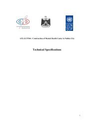
TECHNICAL<br />
INFORMATION 1.3.1<br />
Multi-function panel (MFP)<br />
PC 2625-5 for glazing without transoms<br />
10 years material guarantee*<br />
PC<br />
MFP<br />
made of polycarbonate<br />
UV co-extrusion on the outside<br />
Product description<br />
Technical data<br />
PC 2625-5<br />
The new multi-function panel (MFP) is an<br />
on-going development of the well-known hollow Structural width 600<br />
Unit<br />
mm<br />
chamber panes, but it has a moulded on coupling Thickness 55/25 mm<br />
and does not need a transom system. Weight 3,40 approx. kg/qm<br />
Made of polycarbonate, the MFP offers U-value 1,55 W/qm K<br />
excellent weatherproof properties at<br />
high and low temperatures. E-module 2200 N/qmm<br />
These properties are safeguarded by the Expansion coefficient 0,065 mm/m °C<br />
co-extruded UV protection layer on both sides. Temperature resistance short 130 °C<br />
Also available with heat-reflecting constant 115 °C<br />
HEATBLOC surface. Transmission clear 62 approx. %<br />
In combination clear or opal anti-blind inside. opal anti-blind 44 approx. %<br />
HEATBLOC<br />
a.A<br />
Radius minimum 6000 mm<br />
Thanks to the moulded-on coupling, the UV transmittance 0 %<br />
panels can be clipped on safely and easily. Fire behaviour B 2 DIN 4102<br />
The proven accessories and frame system<br />
allows for versatile, safe and economical<br />
installation. An additional transom profile<br />
Permitted spans*<br />
can drastically increase the span width. Post-and-beam spacing in cm with reinforcement<br />
vertical Normal areas Edge Profile 2180<br />
Application areas 0 - 8 m 220 110<br />
Thanks to the good U-value from the 5-shell design 8 - 20 m 120 60<br />
together with the coupling on the outside,<br />
this panel is simply ideal for economic<br />
Coupling always outside!<br />
roof and facade glazing for 60 ° 200 100<br />
tennis and sports halls 45 - 60 ° 160 80<br />
cantilevered skylights without transoms (curved) 30 - 45 ° 150 60<br />
gable roof glazing 15 - 30 ° 140 60<br />
flat sloping roofs 5 - 15 ° 130 60<br />
warehouse units<br />
Skylight strip, curved<br />
agricultural and sales greenhouses Normal range span up to 400 cm 600<br />
Other permitted spans: please enquire<br />
Guarantee according to our guarantee declaration,<br />
*Values apply for closed buildings in normal area and edge<br />
see also TECHNICAL INFORMATION PC Subject to technical alterations 1.3.1.07.05<br />
These details refer to our current state of know-how and do not claim to be complete.<br />
Subject to technical alterations. Please check for yourself whether our products are suitable for your purpose.
Technical Specifications Sports center -<strong>Ramallah</strong> FIRST OPTION<br />
<strong>Ramallah</strong> Municipality<br />
Project Name:<br />
<strong>Ramallah</strong> <strong>Recreational</strong> <strong>Complex</strong><br />
Phase 1<br />
Sports Center<br />
<strong>Ramallah</strong>, Palestine<br />
Volume VI<br />
GENERAL AND PARTICULAR SPECIFICATIONS<br />
B- Electrical Specification<br />
SPORT HALL<br />
Funded by: IBSA<br />
INDIA BRAZIL SOUTH AFRICA<br />
Through:<br />
United Nations Development Programme<br />
Programme Assistance to the Palestinian people<br />
Designed by<br />
First Option- Amara<br />
Architects, Engineers & Construction Managements<br />
2009<br />
1
DIVISION 1<br />
ELECTRICAL<br />
TABLE OF CONTENTS<br />
Section No.<br />
Title<br />
1 BASIC ELECTRICAL REQUIREMENTS<br />
2 ELECTRICAL RACEWAYS<br />
3 WIRES AND CABLES<br />
4 ELECTRICAL BOXES AND FITTINGS<br />
5 ELECTRICAL CONNECTIONS FOR EQUIPMENT<br />
6 WIRING DEVICES<br />
7 CIRCUIT AND MOTOR DISCONNECTIONS<br />
8 SUPPORTING DEVICES<br />
9 ELECTRICAL IDENTIFICATION<br />
10 UNDERGROUND ELECTRIC SERVICES<br />
11 POWER DISTRIBUTION BOARDS<br />
12 LOW VOLTAGE PROTECTIVE DEVICES<br />
13 EARTHING SYSTEMS<br />
14 PANEL BOARDS<br />
15 MOTOR CONTROL CENTERS<br />
16 MOTOR STARTERS<br />
17 ENCLOSED CONTACTORS<br />
18 ENCLOSED TRANSFER SWITCH<br />
19 INTERIOR AND EXTERIOR LIGHTING<br />
20 EMERGENCY LIGHTING<br />
21 EMERGENCY POWER GENERATOR SYSTEM<br />
22 LIGHTNING PROTECTION SYSTEMS<br />
23 FIRE ALARM / LIFE SAFETY SYSTEM<br />
24 TELEPHONE SYSTEM<br />
25 PUBLIC ADDRESS SYSTEM<br />
26 CLOSED CIRCUIT TELEVISION (CCTV) SYSTEM<br />
27 UPS<br />
28 HAND DRAYERS<br />
29 TESTING AND COMMISSIONING
SECTION 1<br />
BASIC ELECTRICAL REQUIREMENTS<br />
PART 1 GENERAL<br />
1.01 GENERAL<br />
A. All general Provisions contained within this, or any other, section of the specification<br />
shall be fully applicable to each and every other section.<br />
B. All work carried out on the installation shall be carried out in a neat, efficient and<br />
workmanlike manner, to provide for proper operation, maintenance and repair. The work<br />
shall be in accordance with the requirements of these Specifications, and shall fulfill their<br />
true intent and meaning. No deviations from these Specifications and/or Drawings shall<br />
be made without written approval of the Engineer.<br />
C. These Specifications and associated drawings form a composite set of documents,<br />
intended for the selection and installation of equipment having the general and specific<br />
characteristics as detailed.<br />
D. Unless otherwise specifically stated, the installation shall be left complete, tested and<br />
ready for operation in all respects and fully integrated and co-ordinated with all other<br />
construction.<br />
E. The Contractor shall submit proof, if requested by the Engineer that the materials,<br />
appliances, equipments or devices that he furnishes and installs under this contract, meet<br />
the requirements of NEC, BS, NFPA as regards fire and casualty hazards.<br />
1.02 SCOPE OF WORK<br />
A. The work under this division of the specifications shall include furnishing all labor,<br />
materials. equipment and services to furnish and install the complete electrical system,<br />
putting into operation, tested and commissioned as shown on the accompanied drawings<br />
and specified herein. The work includes, but is not limited to, the following principal<br />
systems and equipments:<br />
- Power Distribution Systems<br />
- Lighting Systems<br />
- Low Current Systems<br />
- Power requirements to all mechanical and special systems<br />
1.03 ELECTRICAL SUPPLY<br />
A. The Medium Voltage electrical supply from Electrical CO shall be:<br />
3 phase, 11or 33 KV,Delta , 50 Hertz.<br />
B. The low Voltage electrical system shall be 3 phase, 4 wires, 400 volts, 50 Hertz earthed<br />
Royal Electromechanical Eng.<br />
Consultant Engineers<br />
BASIC ELECTRICAL REQUIREMENTS<br />
SEC.1 - 1
neutral system.<br />
1.04 SUPPLIER OF LOW CURRENT & SPECIAL SYSTEMS<br />
A. The contractor shall assign a specialist supplier/designer for all low current and special<br />
systems.<br />
B. The suppliers of these systems shall check the design and submit their shop drawings and<br />
materials based on the requirements of the construction documents and the related<br />
international standards.<br />
C. The shop drawings and as-built drawings shall be stamped by the suppliers.<br />
D. The suppliers shall support their submittals with satisfactory calculations.<br />
E. The contractor shall bear the cost of any extra item found necessary to have a properly<br />
functional system.<br />
1.05 CO-ORDINATION<br />
A. The Contractor shall be held solely responsible for the proper co-ordination of all phases<br />
of the Work and timely delivery to the site of all equipment and materials for proper<br />
execution of the Work.<br />
It is the sole responsibility of the Contractor to fully co-ordinate the Work with all or any<br />
other disciplines and to ensure proper phasing of the Work to ensure continuity of all<br />
works under this Contract. If it becomes necessary to remake any part of these Works or<br />
that of any other discipline or trade as a result of poor or badly timed co-ordination, then<br />
all costs associated with remaking those Works will be borne by the Contractor.<br />
B. The contractor shall co-ordinate with all supply Undertakings and Authorities and shall<br />
include for attendance along with all costs involved in re-directing existing services.<br />
C. The Contractor shall take into consideration all statutory and local requirements issued by<br />
the Electricity Local Authority, Central Government, Broadcasting Authority, Telephone<br />
and Telecommunications Authorities, Civil Defence along with any other requirements to<br />
be considered for the correct and legal operation of the electrical and telecommunication<br />
installation or equipment connected to the installation as part of this Contract.<br />
D. The Contractor shall be held responsible for the coordination with all electrical and<br />
mechanical systems’ suppliers. He shall include in his cost all the electrical requirements<br />
(even if they were not mentioned in the BoQ or drawings) to have a fully functional<br />
system as specified and as recommended by the manufacturer and/or the international<br />
standard.<br />
1.06 CLIMATE CONDITIONS<br />
A. External to building and in non-air conditioned spaces, all apparatus shall be rated for an<br />
Royal Electromechanical Eng.<br />
Consultant Engineers<br />
BASIC ELECTRICAL REQUIREMENTS<br />
SEC.1 - 2
ambient temperature maximum of 55 o C, minimum of -0 o C and a maximum humidity of<br />
100% rh.<br />
B. In air conditioned buildings, all apparatus shall be rated for ambient temperature of 45°C<br />
maximum; minimum of 0° C and a maximum humidity of 85% rh<br />
C. When equipment is installed in direct sunlight, it shall either be shielded from direct<br />
radiation or suitably rated for additional solar gains.<br />
D. All apparatus shall be rated for continuous services twenty four hours a day, seven days a<br />
week throughout its normal rated life, except for necessary routine maintenance.<br />
1.07 ACCESSIBILITY<br />
A. All work shall be so installed as to be accessible for operation, maintenance and repair.<br />
Deviations from the drawings may be made to accomplish this, but no change shall be<br />
made without written approval from the Engineer. Access door/panels locations shall be<br />
approved by the Engineer before installation work is commenced.<br />
1.08 STORAGE OF MATERIALS AND EQUIPMENT<br />
A. All material and equipment, fixed or unfixed, shall be protected against corrosion,<br />
deterioration and ingress of foreign matter. All equipment shall be kept clear of the floor<br />
or ground by means of wooden bearers or other means, and shall be protected against the<br />
weather.<br />
1.09 PREVENTION OF NOISE AND VIBRATION<br />
A. Provision shall be made to minimize noise and vibration. However, different<br />
manufacturer's equipment will have varying sound and vibration characteristics. The<br />
Contractor shall be entirely responsible for ensuring that equipment installed does not<br />
transmit unnecessary noise or vibration.<br />
B. All equipment installed in plant rooms and outside areas shall not be audible in the<br />
occupied areas.<br />
C. Any vibration isolators, isolating bases, flexible connections, silencers, other acoustic<br />
treatment or anti-vibration precautions necessary shall be included in the rates for the<br />
equipment.<br />
D. The Contractor shall submit proof of the selected noise proofing measures to the Engineer<br />
before commencement of work.<br />
E. The Contractor shall submit to the Engineer for approval the noise generation by the plant<br />
selected so that structural soundproofing measures can be evaluated. This means either<br />
data on the acoustic capacity level in relation to frequency, or the sound pressure level<br />
measured at 1 meter from the plant at octave median frequencies from 63 Hz to 4000Hz.<br />
Details of the spatial and operational conditions shall also be given.<br />
Royal Electromechanical Eng.<br />
Consultant Engineers<br />
BASIC ELECTRICAL REQUIREMENTS<br />
SEC.1 - 3
F. All costs of noise sound level measurements and any repeat measurements, necessary if<br />
acoustic requirements are not met, shall be allowed for by the Contractor.<br />
1.10 GUARDS<br />
A. All moving parts of machinery shall be protected by strong guards to adequately protect<br />
all personnel working on or in the vicinity of equipment. The guards shall be constructed<br />
in such a manner that the movement of drive belts and rotation of shafts may be readily<br />
observed without removal of the guard.<br />
B. All 'live' parts of electrical equipment shall be protected in such a way to adequately<br />
protect all personnel working on or in the vicinity of equipment from injury.<br />
C. Wherever possible, all protective guards shall be supplied by the equipment manufacturer.<br />
All guards shall be strongly attached to equipment and shall be designed to be easily<br />
removed for access, servicing, adjustment and maintenance.<br />
1.11 SIGNS AND NOTICES<br />
A. All signs and notices shall be provided for identification, warning, instructions, etc and as<br />
required by the local authorities both in Arabic and English with the Arabic version being<br />
above or to the right of the English version, and as directed by Engineer.<br />
B. A schedule of all signs and notices with proposed Arabic translations shall be approved<br />
by the Engineer prior to manufacture.<br />
1.12 GOVERNING CONDITIONS<br />
A. The entire electrical installation shall in all respects comply with the requirements of the<br />
following.<br />
1- International Electro technical Commission (IEC).<br />
2- British Standards (BS).<br />
3- American Standards (NFPA/ANSI/NEMA/NEC)<br />
4- International Organization of Standardization (ISO).<br />
5- European Committee for Electrical Standardization (CENELEC).<br />
6- International Telegraph and Telephone Consultive committee (CCITT).<br />
7- Telecommunications and Electronic Industry Association (TIA/EIA).<br />
8- Requirements stated within this Specification.<br />
Royal Electromechanical Eng.<br />
Consultant Engineers<br />
BASIC ELECTRICAL REQUIREMENTS<br />
SEC.1 - 4
1.13 MOUNTING HEIGHTS<br />
A. Unless otherwise stated on the drawings, the following shall be mounting heights of<br />
equipment centre lines above finished floor level;<br />
Panel Board/MCC<br />
Isolating Switch<br />
Equipment Connection Units<br />
Light Switch<br />
Dimmer Switch<br />
Push button station<br />
Wall mounted telephone<br />
Fire alarm manual call point<br />
Fire alarm sounder<br />
Fire alarm panels<br />
Power Socket outlet<br />
Telephone socket<br />
Data Outlet<br />
TV/Radio antenna socket<br />
Remote Control Panel<br />
Wall mounted video I/C unit<br />
Wall mounted speaker<br />
1800mm (Top of panel above FFL)<br />
1300mm<br />
1300mm<br />
1300mm (100mm from door frame)<br />
1300mm<br />
1300mm<br />
1300mm<br />
1500mm<br />
2200mm<br />
1800mm (Top of panel above FFL)<br />
600mm<br />
600mm<br />
600mm<br />
600mm<br />
1800mm<br />
1600mm<br />
1800mm<br />
Where accessories with varying mounting heights (e.g. light switch and socket outlet) are<br />
shown in approximately the same location, their centre lines shall be aligned vertically.<br />
Any discrepancy found between these mounting heights and other disciplines e.g.<br />
architectural drawings, shall be brought to the notice of the Engineer for final decision.<br />
1.14 LABEL AND IDENTIFICATION<br />
A. Each item of the electrical installation including electrical switchgear, control gear etc.<br />
shall be fitted with a non-corrodible label clearly indicating its function, circuit number<br />
and phase.<br />
B. Each label shall be made of white plastic not less than 50mm x 12mm high suitably<br />
engraved with black 5mm high letters and fixed by means of two brass set screws, nuts,<br />
and shake proof washers.<br />
C. Warning labels made of red plastic with white letters at least 12mm high reading<br />
"DANGER 220 VOLTS" as appropriate shall be fixed to the lids, covers or doors of any<br />
equipment which contains terminals or conductors connected to more than one phase of a<br />
low voltage supply. The method of fixing shall be as detailed above.<br />
D. Prior to final testing the Contractor shall confirm that all labeling is intact over the whole<br />
site and that all cables have been fitted with circuit markers.<br />
E. All conductors shall have their outer covering colored to suit the phase to which they are<br />
connected.<br />
Royal Electromechanical Eng.<br />
Consultant Engineers<br />
BASIC ELECTRICAL REQUIREMENTS<br />
SEC.1 - 5
F. An instruction notice giving details of first aid treatment for electric shock shall be<br />
positioned in an approved position in each switch room. Manufacturer's or Contractor's<br />
names or trademarks shall not be exhibited anywhere through the installation without the<br />
prior approval and permission of the Engineer with exception that the Contractor's name<br />
and address may be fixed in an approved position on the main intake switchboard.<br />
G. All labels shall be in English and Arabic.<br />
1.15 VERMIN PROOFING<br />
A. All items of electrical equipment shall be adequately vermin proofed.<br />
B. Where cables enter or leave the bottoms of switchboards, or pass through pipe ducts, they<br />
shall be sealed by the use of hard wood plugs treated with vermin repellant and<br />
surrounded by mastic sealant.<br />
C. All spare pipe ducts shall be similarly sealed by the use of solid hard wood plugs.<br />
D. Alternative methods of vermin sealing will be accepted, but the written comments of the<br />
Engineer must be obtained prior to installation.<br />
1.16 FIRE AND SAFETY PRECAUTIONS<br />
A. The whole of the works shall be carried out with care and so arranged as to minimise the<br />
risk of fire and the extent of damage resulting from any outbreak of fire.<br />
1.17 CLEANING DOWN<br />
A. The Contractor shall allow in his tender for the final cleaning down and painting of all<br />
scratched or damaged electrical apparatus, panel boards, cubicle panels, distribution<br />
boards and transformers.<br />
1.18 MATERIAL SUBMITTALS<br />
A. The Contractor shall submit samples and full relevant manufactures literature for all<br />
material proposed for the project, in accordance with the requirements of the relevant<br />
sections of this specification.<br />
B. No order shall be placed until the Contractor has obtained full written approval of the<br />
relevant material submittal from the Engineer.<br />
C. The Contractor shall submit a sample of the exact make, model and finish proposed for<br />
each material required.<br />
D. Manufacturer's performance data and certified factory drawings giving full information<br />
pertinent to the adequacy of the relevant equipment shall be submitted for approval.<br />
E. Submittal shall be made in a manner to ensure complete information regarding what is<br />
Royal Electromechanical Eng.<br />
Consultant Engineers<br />
BASIC ELECTRICAL REQUIREMENTS<br />
SEC.1 - 6
eing offered and in a manner that facilitates easy filing and ready access to all data.<br />
F. Where data certified drawings or other required information is not available until after<br />
orders have been placed, the Engineer may give provisional approval until all requested<br />
drawings and information have been supplied to the Engineer and approved by him. It is<br />
the Contractor's responsibility to ensure that all necessary information is supplied to the<br />
Engineer in accordance with the progress of work.<br />
G. Should the Engineer give provision approval due to lack of complete information, and<br />
should the missing information not eventually meet with approval, the Engineer shall not<br />
be held responsible for any delay of additional expense incurred. For equipment where<br />
delivery from the manufacturer is likely to be prolonged, it is essential that the Contractor<br />
provided the material submittal at the earliest possible date, so as to ensure approval and<br />
orders in complete conformity with the progress of the works.<br />
1.19 SHOP DRAWINGS<br />
A. The Contractor shall submit for approval by the Engineer detailed construction drawings<br />
before starting work. These drawings shall comply with and complement the Tender<br />
Documents in showing physical layout of all equipment, exact location of all equipment,<br />
lighting, columns, luminaries and cables routings including dimensioned locations of<br />
underground cables, construction and installation details, wiring diagrams, etc. No work<br />
shall be started on site until approval of the Drawings has been given in writing by the<br />
Engineer. The scale of the shop drawings shall be 1:100.<br />
1.20 AS BUILT DRAWINGS<br />
A. The Contractor shall supply to the Engineer 'As Built' drawings all in accordance with the<br />
requirements for 'Shop Drawings' updated to show the exact manner in which equipment<br />
is installed and shall be completely cross referenced to submittals and instruction<br />
manuals, so that they form an integrated reference to details of equipment, method of<br />
installation and maintenance.<br />
B. Upon completion of the installation, record drawings shall be submitted on each system<br />
before final acceptance of the work. The contractor shall furnish to the Engineer a set of<br />
record drawings including system diagrams for each system.The record drawings masters<br />
shall be on reproducible mylar film, uniformly sized as required for legibility and<br />
reproduction and on high density floppy or compact disks.<br />
1.21 DOCUMENTS<br />
A. Maintenance Literature: Prior to the final acceptance of the installation the Contractor<br />
shall submit to the Engineer manuals for all equipment supplied under the Contract. The<br />
manuals shall be A4 size bound in loose leaf binders or booklets suitably enclosed and<br />
including the following:<br />
1. Single line diagram of the complete network,<br />
2. Control, protection and circuit diagrams for all equipment,<br />
3. Setting up, commissioning and operating instructions,<br />
Royal Electromechanical Eng.<br />
Consultant Engineers<br />
BASIC ELECTRICAL REQUIREMENTS<br />
SEC.1 - 7
1.22 SPECIAL TOOLS<br />
4. Trouble shooting procedures,<br />
5. Maintenance instructions including schedules for preventative<br />
maintenance,<br />
6. Complete recommended spares list including manufacturers name and<br />
catalog number.<br />
7. Name of manufacturers' local authorized representatives and service agent.<br />
A. The Contractor shall supply as part of this contract all special tools required for equipment<br />
maintenance.<br />
END OF SECTION 1<br />
Royal Electromechanical Eng.<br />
Consultant Engineers<br />
BASIC ELECTRICAL REQUIREMENTS<br />
SEC.1 - 8
SECTION 2<br />
ELECTRICAL RACEWAYS<br />
PART 1 GENERAL<br />
1.01 GENERAL REQUIREMENTS<br />
A. Examine all other sections of the Specification for requirements which affect work of this<br />
Section. Cooperate with such trades to assure the steady progress of all work under the<br />
Contract.<br />
1.02 SCOPE AND DESCRIPTION OF WORK<br />
A. The requirements of this section shall apply to all electrical raceways referred to on the<br />
drawings and elsewhere within this Specification.<br />
B. The types of electrical raceways required shall comprise the following:-<br />
1. Steel Conduits.<br />
2. Flexible Conduits.<br />
3. PVC Conduits.<br />
4. EMT Conduits.<br />
5. Cable Trays.<br />
6. Cable Trunkings (Metal).<br />
7. Cable Trunkings (PVC).<br />
8. Cable Ladders.<br />
9. Underground Ducts<br />
1.03 QUALITY STANDARDS<br />
A. The manufacturer shall be regularly engaged in the manufacture of electrical raceways of<br />
the type and capacities required, whose products have been in satisfactory use in similar<br />
service for not less than 5 years.<br />
B. The raceways furnished under these specifications shall conform to all applicable<br />
standards of SASO and B.S.<br />
1.04 SUBMITTAL<br />
A. The Contractor shall submit samples and manufacturer's data on all electrical raceway<br />
system materials, together with samples of the proposed materials.<br />
1.05 DELIVERY, STORAGE AND HANDLING OF MATERIALS<br />
A. The Contractor shall provide color-coded thread protectors on the exposed threads of<br />
metal conduit, handle raceways carefully to prevent end-damage and avoid scoring the<br />
finishes. Where possible the raceways shall be stored indoors. If necessary to store<br />
outdoors, the raceways shall be elevated well above ground and enclosed with durable<br />
Royal Electromechanical Eng.<br />
Consultant Engineers<br />
ELECTRICAL RACEWAY<br />
SEC .2 -1
waterproof wrapping.<br />
PART 2 PRODUCTS<br />
2.01 METAL CONDUITS<br />
A. All metal conduits shall be heavy gauge welded steel complying with BS 4568, not less<br />
than 20mm diameter and finished with hot dipped galvanising providing heavy protection<br />
(Class 4) both inside and outside. All conduit and fittings shall be free from rust or other<br />
defects.<br />
B. All conduit fittings shall be malleable iron manufacture complying with BS 4568.<br />
C. All fittings shall have a hot dipped galvanized finish.<br />
D. All bushes shall be hexagonal headed, heavy duty, long threaded brass bushes complete<br />
with serrated tempered shakeproof washers. All bends shall be cold set. All tees shall be<br />
made using circular tee conduit boxes.<br />
E. All saddles shall be of the spacer bar type and of the same finish as that of the conduit<br />
which they are being used to secure.<br />
F. A tapped earth connection facility shall be provided in every box.<br />
G. All accessory boxes shall have one adjustable fixing lug to facilitate final leveling of<br />
accessory.<br />
2.02 FLEXIBLE CONDUITS<br />
A. Flexible conduits, not less than 20 mm diameter, shall only to be used for final connection<br />
to items of fixed equipment subject to vibration.<br />
B. Flexible conduit and adaptors shall be manufactured in accordance with BS 731 Part 1.<br />
C. Brass adaptors shall be provided for connection at either end of the flexible conduit and<br />
should be of the compression type.<br />
D. Flexible conduit shall be of the weather proof liquid-tight type having an overall PVC<br />
sheath. No length shorter than 500mm of flexible conduit shall be used unless specified<br />
elsewhere in this specification.<br />
2.03 PVC CONDUITS<br />
A. All PVC conduits shall be U.P.V.C. Rigid Conduits complying with BS 6099-2-2/614-2-2<br />
I.E.C. heavy gauge in all respects, and may be used where ambient temperatures do not<br />
exceed 75 o C.<br />
B. All conduit fittings shall confirm to BS 6099-2-2/IEC 614-2-2 standards and BS 4607<br />
Royal Electromechanical Eng.<br />
Consultant Engineers<br />
ELECTRICAL RACEWAY<br />
SEC .2 -2
Part 5.<br />
C. No conduit shall be less than 20mm diameter.<br />
D. Conduit boxes shall be of the B.E.E.S.A. circular pattern with appropriate spout entries<br />
and 50.8mm accessory fixing centres.<br />
E. All connections and terminations shall be by means of a manufacturer's standard adaptor.<br />
F. All boxes shall have brass thread inserts for the fixing of accessories or covers.<br />
However care must be taken in the support of totally enclosed lighting fittings. Where<br />
excessive temperatures are likely to occur special insulated boxes shall be used, i.e. of a<br />
pattern specifically designed by the manufacturer to improve weight-loading<br />
characteristics at high temperatures.<br />
G. All tees shall be made using conduit tee boxes. Tangential entry boxes shall be used<br />
where appropriate. Multiple conduits may necessitate the use of large U.P.V.C. adaptable<br />
boxes for junctions.<br />
H. All saddles shall be of the spacer bar type and from the same manufacturer as that of the<br />
conduit which they are being used to secure.<br />
I. A tapped earth terminal shall be provided in every conduit box.<br />
J. All wall mounted accessory boxes shall have one adjustable fixing lug to facilitate final<br />
levelling of accessories.<br />
K. In order to facilitates interchangeability and to eliminate problems of differential<br />
manufacturing tolerances, it is essential that all PVC conduit and appropriate accessories<br />
covered by this specification shall be obtained from the same manufacturer.<br />
2.04 ELECTRICAL METALLIC TUBING (EMT)<br />
A. EMT conduits shall be made of galvanized steel.<br />
B. EMT conduits shall comply with ANSI/NEMA standards.<br />
C. EMT fittings and accessories shall be made of galvanized steel.<br />
D. Compression type connectors shall be used.<br />
2.05 CABLE TRAYS<br />
A. All cable trays shall be of heavy duty perforated type with return flange.<br />
B. All cable trays shall be manufactured from hot-dip zinc coated steel to BS 2989 with a<br />
standard heavy duty galvanizing coating of 350g/m 2 and Z2 bending grade.<br />
C. All bends, tees, cross units and angles shall be of the same specification as that of the<br />
Royal Electromechanical Eng.<br />
Consultant Engineers<br />
ELECTRICAL RACEWAY<br />
SEC .2 -3
cable tray finish and shall be standard products from the same manufacturer as the cable<br />
tray. Site fabrication shall not be permitted.<br />
D. Cable trays and accessories shall be of a thickness of not less than:<br />
1.5mm up to 305mm width.<br />
2.0mm above 305mm width.<br />
E. All fixing brackets, nuts and bolts shall be finished by hot dip galvanizing.<br />
F. Tinned copper earth continuity straps shall be provided at every joint.<br />
G. Where cable tray crosses building expansion joints, the tray shall be installed as shown in<br />
the typical drawing details.<br />
H. Where cable tray carries 13.8kV cable a tray lid shall be installed.<br />
2.06 CABLE TRUNKING (METAL)<br />
A. Metal cable trunking shall comply with BS 4678 Part 1: Class 3 and shall be<br />
manufactured from galvanized steel sheet to BS 2989.<br />
B. Only purposed made fittings, connectors, covers and accessories by the same<br />
manufacturer as the trunking shall be used and finished in hot dipped galvanized steel to<br />
BS 2989. Site fabrication shall not be permitted.<br />
C. Tinned copper earth straps shall be provided at every joint.<br />
D. Covers shall be of the overlapping type and secured to the trunking by either an approved<br />
clip or screws.<br />
E. In areas subject to corrosive atmospheres, e.g. chlorine, all trunking shall be painted with<br />
chlorinated rubber paint.<br />
F. Cable trunking shall be used wherever possible to replace multiple conduit runs as shown<br />
on drawing and as approved by Engineer.<br />
2.07 CABLE TRUNKING (PVC)<br />
A. Heavy Duty U.P.V.C. trunking with clip on lid (all insulated) shall be used wherever<br />
possible to replace multiple conduit runs. Where applicable, trunking shall comply with<br />
the requirements contained in BS 4678 Part 4. Any non-standard trunking accessories<br />
shall be fabricated by the manufacturer, no site fabrication shall be allowed.<br />
B. In order to facilitate interchangeability and to eliminate problems of differential<br />
manufacturing tolerances, it is essential that all PVC cable trunking and appropriate<br />
accessories covered by this specification shall be obtained from the same manufacturer.<br />
Royal Electromechanical Eng.<br />
Consultant Engineers<br />
ELECTRICAL RACEWAY<br />
SEC .2 -4
2.08 CABLE LADDERS<br />
A. All cable ladders shall be heavy (2mm) gauge, manufactured from hot-dip galvanized<br />
sheet steel to BS 2989;G350 coating weight (350g/m 2 ) and Z2 bending grade.<br />
B. All couplers, bends, tees etc shall be by the same manufacturer as the ladder.<br />
C. Ladder system supports shall be determined in accordance with the manufacturer's<br />
structural information to ensure undue stress or bending does not occur.<br />
D. In areas subject to corrosive atmosphere, eg. chlorine, the ladders shall have a PVC finish.<br />
E. Tinned copper earth straps shall be provided at every joint.<br />
2.09 UNDERGROUND DUCTS<br />
A. Underground duct banks shall be of individual UPVC rigid conduits complying with BS<br />
6099-2-2/614-2-2 I.E.C. heavy gauge.<br />
PART 3 EXECUTION<br />
3.01 METAL CONDUIT INSTALLATION<br />
A. Where conduits are to be cast in concrete, they shall be secured using crumpets, clips or<br />
saddles as approved by the Engineer.<br />
B. All ends of conduits shall be reamed to remove all traces of burrs.<br />
C. Conduit threads shall be of sufficient length to allow conduits to butt together within<br />
couplers.<br />
D. Oil and grease shall be removed from all threads.<br />
E. Conduits shall be supported at intervals of 1.5 m in isolated positions or 1 m in accessible<br />
situations.<br />
F. Conduit shall not be permitted to be installed closer than 75 mm to pipes of other<br />
services.<br />
G. All conduit boxes not to be fitted with accessories shall have metal cover plates which<br />
shall be overlapping where flush boxes are used.<br />
H. 'Draw in' boxes shall be provided in conduit runs exceeding 3 m in length. 'Draw in' boxes<br />
shall be at maximum 12 m spacing and readily accessible at all times. Adaptable junction<br />
boxes shall also be accessible at all times for inspection and maintenance.<br />
J. Inspection elbows, bends or tees shall not be permitted for flush installation.<br />
Royal Electromechanical Eng.<br />
Consultant Engineers<br />
ELECTRICAL RACEWAY<br />
SEC .2 -5
K. Care shall be taken to prevent water, dirt and debris from entering the conduit system.<br />
L. Extension rings shall be used where boxes are found not to be flush with the finished<br />
surface.<br />
M. Conduits and conduit accessories shall be protected from rust and mechanical damage.<br />
Exposed conduit threads and damaged or rusty areas shall be painted, using an oxide<br />
undercoat and aluminum paint, after being cleaned to bare metal.<br />
N. Conduits installed in areas subject to corrosive atmospheres shall be painted with<br />
chlorinated rubber paint after the installation is complete.<br />
O. Under no circumstances shall metal conduit be used as a circuit protective conductor<br />
(CPC). Every final sub-circuit shall incorporate its own separate Cu/PVC CPC.<br />
P. Spacing or fill factors shall be applied to all conduits in accordance with chapter 522-08<br />
of the IEE Wiring Regulations, 16th Edition.<br />
Q. EMT conduit shall be used above false ceiling installation.<br />
R. Rigid steel conduits shall be used for exposed installation.<br />
S. Under no circumstances, any conduit shall be allowed to run in the floor screed of toilets,<br />
bathrooms or any other wet area.<br />
3.02 FLEXIBLE CONDUIT INSTALLATION<br />
A. Flexible conduits shall only be used in short lengths, of less than 1m, in cases where a<br />
final connection is required to be made to a fixed item of equipment which is subject to<br />
vibration.<br />
B. Flexible conduits shall be 1.25 x L, L being the direct distance between connection unit<br />
and fixed appliance, up to maximum length of 1m.<br />
C. Purpose made glands shall be used on the ends of all lengths of flexible conduit.<br />
D. A separate Cu/PVC circuit protective conductor shall be included in all lengths of flexible<br />
conduits.<br />
E. Conduits shall be installed so as not to incur undue mechanical strain, damage or<br />
excessive temperatures.<br />
3.03 PVC CONDUIT INSTALLATION<br />
A. Where conduit boxes are not to be fitted with accessories, they shall be fitted with cover<br />
plates which shall be overlapping where flush boxes are used.<br />
Royal Electromechanical Eng.<br />
Consultant Engineers<br />
ELECTRICAL RACEWAY<br />
SEC .2 -6
B. Conduits shall be jointed and terminated utilizing the following appropriate components<br />
as supplied by the conduit manufacturer:<br />
1. Purposed made adaptors and accessories.<br />
2. Permanent adhesive - Solvent cement to produce a rigid watertight joint<br />
when used with standard couplers and accessories.<br />
3. Flexible adhesive - A non-hardening adhesive to be used where expansion<br />
facilities are required in long conduit runs, in conjunction with expansion<br />
coupler.<br />
C. Conduits up to 25 mm diameter may be bent cold with the use of the appropriate bending<br />
spring obtained from the conduit manufacturer. For larger size conduits, it is necessary to<br />
use heat or appropriate manufacturer's standard ready made bends.<br />
D. Adequate allowance shall be made for linear expansion and contraction of the conduits<br />
under normal working temperature variations, as follows:<br />
1. Expansion couplers shall be used on all straight runs of conduit exceeding<br />
6 meters in length.<br />
2. Conduit shall be free to slide within saddles.<br />
3. Allowance for expansion in cast in-situ installation is normally only<br />
required to effect structural movement at building expansion joints.<br />
E. Conduit shall be supported at intervals of 1.5 meters in isolated positions or 1 meter in<br />
accessible situations. Where working temperatures tend to be high, this spacing shall be<br />
reduced accordingly.<br />
F. Multiple conduits may necessitate the use of large PVC adaptable boxes for junctions,<br />
which shall be readily accessible at all times.<br />
G. Care shall be taken in the support of totally enclosed lighting fittings. Where excessive<br />
temperature are likely to occur special heat resistant boxes shall be used, i.e. of a pattern<br />
specifically designed to improve weight loading characteristics.<br />
H. Spacing or fill factors shall be applied to all conduit in accordance with chapter 522-08 of<br />
the IEE Wiring Regulations, 16th Edition.<br />
J. Conduits shall not be installed closer than 75 mm to pipes of other services.<br />
K. "Draw-in" boxes shall be installed in all conduit runs exceeding 3 m in length at a<br />
maximum 12 m spacing and shall be readily accessible at all times.<br />
L. Inspection elbows, bend or tees shall not be permitted for flush installation.<br />
Royal Electromechanical Eng.<br />
Consultant Engineers<br />
ELECTRICAL RACEWAY<br />
SEC .2 -7
M. Extension rings shall be used where boxes are found to be not flush with the finished<br />
surface. Care shall be taken to prevent water, dirt, dust or debris from entering the conduit<br />
system.<br />
N. PVC conduits shall be used for embedded installation only.<br />
O. Under no circumstances, any conduit shall be allowed to run in the floor screed of toilets,<br />
bathrooms or any other wet area.<br />
3.04 CABLE TRAY INSTALLATION<br />
A. Where practical cable tray shall be run horizontally and flat or vertically and shall be<br />
supported at distances not exceeding 1.5 m to the building structure using mild steel<br />
brackets. These brackets shall be secured to the building structure using expanded bolts<br />
and washers or built into the building structure during construction.<br />
B. Where cable tray is suspended, 2 No. drop rods shall be used at each suspension point to<br />
an angle iron or channel support to which the cable tray is bolted. The spacing of<br />
suspension points shall be determined in accordance with the manufacturer's structural<br />
information such that undue stress or deflection does not occur.<br />
C. Where cable tray is cut, the open ends shall be painted using an oxide undercoat and an<br />
aluminium top coat. Where the finish is PVC a top coat of liquid PVC solution shall be<br />
applied after the completion of the cable tray installation.<br />
D. Cable trays run parallel with walls shall not be mounted closer than 75mm to the wall.<br />
E. All cables shall be secured to the cable tray at distances in accordance with table 4A of the<br />
IEE Wiring Regulations, 16th Edition, using suitable clips.<br />
F. Bare copper cables shall not be run on cable tray.<br />
G. Earth continuity shall be ensured by means of tinned copper earth straps bolted across<br />
each joint. Flexible braided straps shall be used for expansion joints.<br />
3.05 CABLE TRUNKING INSTALLATION<br />
A. Cable trunking shall be fixed securely to the building structure at intervals not exceeding<br />
1.5 m.<br />
B. Where vertical runs of trunking exceed 3 m in length, pin racks shall be fitted by the<br />
Contractor.<br />
C. Spacing or fill factors shall be applied to all cable trunking in accordance with chapter<br />
522-08 of the IEE Wiring Regulations, 16th Edition.<br />
D. For metal trunking installations, earth continuity shall be ensured by means of tinned<br />
copper earth straps bolted across each joint. Flexible braided straps shall be used for<br />
Royal Electromechanical Eng.<br />
Consultant Engineers<br />
ELECTRICAL RACEWAY<br />
SEC .2 -8
expansion joints.<br />
E. Metal trunking cut during installation shall have the cut ends painted with an oxide<br />
undercoat and an aluminium top coat.<br />
F. Where metal trunking is installed in areas subject to corrosive atmospheres, the complete<br />
trunking installation shall be painted with a chlorinated rubber paint after the installation<br />
is complete.<br />
G. Expansion joints with gaps shall be incorporated in all PVC trunking runs in excess of 6<br />
metres in length. External couplings shall have elongated slots and fixing holes shall be<br />
drilled oversize to give freedom of linear movement. Internal couplings shall be securely<br />
fixed at one end by use of thiscotrophic adhesive leaving the other end free for linear<br />
movement.<br />
H. Bare copper or aluminium cables shall not be run in metal trunking.<br />
3.06 CABLE LADDER INSTALLATION<br />
A. Where practical, cable ladders shall be run horizontally and flat or vertically and shall be<br />
supported at distances not exceeding 1.5 m to the building structure using mild steel<br />
brackets. These brackets shall be secured to the building structure using expanded bolts<br />
and washers or built into the building structures during construction.<br />
B. Where cable ladder is suspended, 2 No. drop rods shall be used at each suspension point<br />
to an angle iron or channel support to which the cable ladder is bolted. The spacing of<br />
suspension points shall be determined in accordance with the manufacturer's structural<br />
information such that undue stress of defection does not occur.<br />
C. Where cable ladder is cut, the open ends shall be painted using an oxide undercoat and an<br />
aluminium top coat. Where the finish is PVC, a top coat of liquid PVC solution shall be<br />
applied after the completion of the cable ladder installation.<br />
D. Cable ladders run parallel with walls shall not be mounted closer than 75 mm to the wall.<br />
E. All cables shall be secured to the cable ladder with suitable clips at distances in<br />
accordance with chapters 521-03 and 522-08 of the IEE Wiring Regulations, 16th Edition,<br />
a maximum number of 4 cables may be secured by one clip.<br />
F. Bare copper cables shall not be run on cable ladder.<br />
G. Earth continuity shall be ensured by means of tinned copper earth straps bolted across<br />
each joint. Flexible braided straps shall be used for expansion joints.<br />
3.07 UNDERGROUND DUCTS AND MANHOLES<br />
A. Multiple conduit runs or banks shall be supported on preformed non-metallic separators.<br />
Spacing between separators shall be close enough to prevent sagging of conduits and<br />
Royal Electromechanical Eng.<br />
Consultant Engineers<br />
ELECTRICAL RACEWAY<br />
SEC .2 -9
eaking of couplings and water tight seals. Separators shall be secured with cords where<br />
necessary and not tie wires.<br />
B. Duct lines shall have a continuous slope downwards away from building. Trenches shall<br />
be excavated along straight lines so the elevation can be adjusted if necessary to avoid<br />
unseen obstructions.<br />
C. During construction, partially completed duct lines shall be protected from the entrance of<br />
debris such as mud, sand, and dirt by means of suitable conduit plugs. As each section of<br />
duct line is completed a test mandrel not less than 300 mm long with a diameter 6 mm<br />
less than the size of the conduit shall be drawn through each conduit, after which a brush<br />
with stiff bristles shall be drawn through until the conduit is clear or all particles of earth,<br />
sand or gravel; conduit plugs shall then be immediately installed.<br />
END OF SECTION 2<br />
Royal Electromechanical Eng.<br />
Consultant Engineers<br />
ELECTRICAL RACEWAY<br />
SEC .2 -10
SECTION 3<br />
WIRES AND CABLES<br />
PART 1 GENERAL<br />
1.01 GENERAL REQUIREMENTS<br />
A. Examine all other sections of the Specification for requirements which affect work of this<br />
Section whether or not such work is specifically mentioned in this Section.<br />
1.02 SCOPE AND DESCRIPTION OF WORK<br />
A. The requirements of this section shall apply to all multicore and single core cables,<br />
referred to on the drawings and elsewhere within this Specification.<br />
B. The types of cables shall have copper conductors and comprise the following:-<br />
1. Single core PVC insulated wires and cables.<br />
2. Flexible multi-core cables.<br />
3. XLPE/SWA/PVC cables or XLPE/PVC cables.<br />
1.03 QUALITY STANDARDS<br />
A. Cables shall only be purchased from manufactures specializing in the manufacture or the<br />
type of cable mentioned.<br />
B. Cables shall generally be manufacturer's standard construction and materials. Where this<br />
contradicts any part of this Specification, the contractor shall state so at the time of tender.<br />
C. Manufacturer's shall provide proof of supply of similar types of cables to known users for<br />
a period not less than 5 years.<br />
D. All equipment furnished under this specification shall conform to applicable standards of<br />
SASO and BS.<br />
1.04 SUBMITTAL<br />
A. The Contractor shall submit samples of each type of cable they are offering.<br />
B. For all cables the Contractor shall submit the following manufacturers’ details:<br />
Dimensions<br />
Weights<br />
Construction<br />
Current rating<br />
Manner of installation<br />
Royal Electromechanical Eng.<br />
Consultant Engineers<br />
WIRES AND CABLES<br />
SEC.3 - 1
Maximum conductor operating temperature<br />
Volt drop/amp/metre<br />
Impedance: Separate resistance and reactance values of single and multicore<br />
cables<br />
Resistance of armouring in ohms/1000 metres length of cable<br />
Characteristic curves for short circuit rating<br />
Minimum bending radius<br />
1.05 DELIVERY AND HANDLING OF CABLES<br />
A. End of cables shall be sealed to prevent ingress of moisture.<br />
B. Where cables are transported on drums, these shall have adequate circumference for the<br />
cables.<br />
C. After winding on drums, the cables shall be protected by being completely enclosed.<br />
D. Care shall be taken during transit to avoid damage to cable and drums. Before acceptance<br />
on site, cable drums and cables shall be inspected for:<br />
1. Damage<br />
2. Compliance with specification<br />
3. Quantity<br />
E. Cable, wire and accessories shall be stored in factory installed coverings in a clean, dry<br />
indoor space which provides protection against the weather.<br />
F. Each distribution cable shall be supplied in one continuous length, no joints shall be<br />
permitted.<br />
G. Cables shall be handled with care and every effort made to avoid damage to the cable, to<br />
other services and to building fabric. Recommendations or instructions available from the<br />
cable manufacturers concerning the installation of cables shall be taken into account; in<br />
particular co-axial cables shall not be bent in radius less than six times the overall<br />
diameter. Any damage shall be reported immediately to the Engineer.<br />
H. Cable drums shall be unloaded carefully by means of either a crane or ramp and impact<br />
with the ground shall be avoided. They shall be supported on axles and axle stands while<br />
the cable is being pulled; twisting and abrasion of the cable serving or over sheath shall be<br />
avoided.<br />
I. Cables shall be pulled over cable rollers adequately spaced to prevent the cable being<br />
dragged over ground or other surfaces. For cables pulled into thrust boring or cable ducts<br />
and for all cables exceeding 10 m length, cable stockings shall be used for hauling.<br />
Precautions shall be taken to ensure that strain is taken on the cable cores as well as the<br />
sheath and excessive stain shall be avoided.<br />
Royal Electromechanical Eng.<br />
Consultant Engineers<br />
WIRES AND CABLES<br />
SEC.3 - 2
PART 2 PRODUCTS<br />
2.01 SINGLE CORE PVC INSULATED CABLES<br />
A. Single core cables for lighting and small power shall be of high conductivity copper<br />
stranded wire insulated with PVC 85 0 C, minimum.<br />
B. Cables shall comply with BS 6004 and shall be of 450/750V grade.<br />
C. Cables shall be coloured in accordance with section 514 of the IEE Wiring Regulations,<br />
16th Edition, and BS 3858.<br />
2.02 FLEXIBLE CABLES<br />
A. All flexible cables used for pendant lighting fittings or for final connections to fixed or<br />
portable equipment shall be of 300/500 volt grade and comply with BS 6500.<br />
B. Flexible cables shall be of annealed copper conductors insulated with heat resisting PVC,<br />
sheathed with heat resisting PVC and shall be of circular construction.<br />
C. Cable cores shall be colored in accordance with section 514 of the IEE Wiring<br />
Regulations, 16th Edition, and BS 3858.<br />
2.03 CROSS-LINKED POLYETHYLENE (XLPE) INSULATED UNARMOURED OR<br />
STEEL WIRE ARMORED AND PVC SHEATHED CABLES<br />
A. All low voltage multi-core distribution cables shall be 600/1000 volt grade cross-linked<br />
polyethylene (XLPE) insulated copper conductor, unarmoured or steel wire armoured and<br />
PVC sheathed cables complying with BS 5467.<br />
B. Cable conductors shall be of high conductivity copper wire insulated with cross-linked<br />
polyethylene. The armouring shall consist of a single layer of galvanized steel wire and the<br />
cable shall be sheathed overall with PVC.<br />
C. Steel wire cable armoring shall be securely bonded to earth at each termination by means<br />
of an adequately sized metallic bond which shall be as short and straight as it is<br />
practicable.<br />
D. Cable cores shall be colored in accordance with section 514 of the IEE Wiring<br />
Regulations, 16th Editions, and BS 3858.<br />
E. Joints shall not be allowed in any cable unless approved by the Engineer prior to<br />
execution.<br />
PART 3 EXECUTIONS<br />
3.01 INSPECTION<br />
Royal Electromechanical Eng.<br />
Consultant Engineers<br />
WIRES AND CABLES<br />
SEC.3 - 3
A. The Contractor shall examine the areas and conditions under which the cables are to be<br />
installed and correct any unsatisfactory conditions detrimental to the proper and timely<br />
completion of the work. The Contractor shall not proceed with the work until all<br />
unsatisfactory conditions have been corrected in a manner acceptable to the Engineer.<br />
3.02 SUB-CIRCUIT WIRING - LIGHTING<br />
A. Lighting installation wiring will take the following forms:<br />
1). Single core PVC insulated cables in trunking/conduit for internal wiring.<br />
2). Multi-core XLPE/PVC insulated cables in cable tray, ladder or conduit for internal<br />
wiring.<br />
3). Multi-core XLPE/SWA/PVC in conduit, duct banks or direct buried for external<br />
wiring.<br />
B. The types of lighting luminaries required are detailed on the drawings, and the types of<br />
lighting installations and accessories are detailed elsewhere in this specification and on the<br />
drawings.<br />
C. No conductor smaller than 2.5 sq mm shall be used.<br />
D. All lighting circuit wiring shall be carried out using the "loop-in" system, where<br />
applicable.<br />
E. Each lighting circuit shall be wired as shown on the drawings and in accordance with this<br />
Specification.<br />
F. Each lighting circuit shall have a separate circuit protective conductor throughout to each<br />
light and switch point.<br />
G. Where a lighting circuit is to be installed in trunking or conduit together with any other<br />
circuit(s) deviating from drawings, the circuit conductor must be derated for grouping in<br />
accordance with IEE Wiring Regulations, 16th Edition. This will normally result in the<br />
need to increase the conductor sizes as shown in the schedule.<br />
H. Normal and emergency circuit wiring or cables shall run in separate conduits or in separate<br />
compartments of metal trunking or on separate cable tray/ladder in accordance with IEE<br />
wiring regulations, 16 th edition.<br />
3.03 SUB-CIRCUIT WIRING -SMALL POWER<br />
A. Small power installation wiring will take the following forms:<br />
1. Single core PVC insulated cables in trunking/conduit for internal wiring.<br />
2. Multi-core XLPE/PVC insulated cables in cable tray, ladder or conduit for internal<br />
Royal Electromechanical Eng.<br />
Consultant Engineers<br />
WIRES AND CABLES<br />
SEC.3 - 4
wiring.<br />
3. Multi-core XLPE/SWA/PVC in conduit, duct banks or direct buried for external<br />
wiring.<br />
B. The types of small power installations and accessories required are detailed elsewhere in<br />
this Specification and on the drawings.<br />
C. The small power installations shall be wired using the radial system as described on the<br />
drawings.<br />
D. No conductor smaller than 4.0 sq mm shall be used.<br />
E. Each small power circuit shall have a separate circuit protective conductor throughout to<br />
each outlet.<br />
F. Where a small power circuit it to be installed in trunking or conduit together with any<br />
other circuit(s), deviating from drawings, the circuit conductors must be derated for<br />
grouping in accordance with IEE Wiring Regulation, 16th Edition. This will normally<br />
result in the need to increase the conductor sizes as shown on the drawings.<br />
G. Normal and emergency circuit wiring or cables shall run in separate conduits or in separate<br />
compartments of metal trunking or on separate cable tray/ladder in accordance with IEE<br />
wiring regulations, 16 th edition.<br />
3.04 MAIN-CIRCUIT WIRING - POWER (SINGLE AND 3 PHASE)<br />
A. Power installation wiring will take the form of one of the following:<br />
1. Single core PVC insulated cables in trunking/conduit.<br />
2. Multi-core or single core XLPE/PVC cables in cable tray, ladder or conduit for<br />
internal wiring.<br />
3. Multi-core XLPE/SWA/PVC in conduit, duct bank or direct buried for external<br />
wiring.<br />
B. The types of power installations required for this project are detailed elsewhere in this<br />
Specification and on the drawings.<br />
C. Power installations will generally be wired on a single circuit basis as described on the<br />
drawings and will serve fixed items of equipment.<br />
D. No conductor small than 4.0 sq. mm shall be used.<br />
E. Each power circuit shall have a separate circuit protective conductor.<br />
F. When a power circuit is to be installed in trunking or conduit together with any other<br />
circuit(s) deviating from drawings, the circuit conductors must be derated for grouping in<br />
Royal Electromechanical Eng.<br />
Consultant Engineers<br />
WIRES AND CABLES<br />
SEC.3 - 5
accordance with IEE Wiring Regulations, 16th Edition. This will normally result in the<br />
need to increase the conductor sizes.<br />
G. Normal and emergency circuit wiring or cables shall run in separate conduits or in separate<br />
compartments of metal trunking or on separate cable tray/ladder in accordance with IEE<br />
wiring regulations, 16 th edition.<br />
3.05 FLEXIBLE CABLE INSTALLATION<br />
A. Flexible cables shall not be concealed in any part of the installation.<br />
B. Where flexible cables are subject to heat they shall be constructed containing a minimum<br />
of three cores.<br />
C. All flexible cables are to be of circular construction containing a minimum of three cores.<br />
D. Where portable appliances exceed 200 watt rating, the flexible cable shall not be smaller<br />
than 32/0.20 sq. mm.<br />
E. Flexible cables exceeding 1.8 m in length shall not be allowed, with pride approval of the<br />
Engineer hard wiring shall be taken to within 1.8 m of all equipment or apparatus to be<br />
supplied with prior approval of the Engineer.<br />
3.06 INTERNAL CABLE INSTALLATION<br />
A. Where cables enclosed in conduits are run vertically in excess of 5 m the cables shall be<br />
clamped after passing out of the conduit, so as to relieve strain on the cables, using suitable<br />
approved clamps.<br />
B. Where cables are run in trunking the cables of each circuit or groups of circuits shall be<br />
clipped together using nylon straps or other suitable straps or clips. Vertical runs of<br />
trunking exceeding 5 m shall be supplied with pin racks to relieve the strain on cables.<br />
C. Suitable precautions shall be taken during multiple circuit wiring follows a common route<br />
then the wiring shall be installed in trunking rather than multiple conduits.<br />
D. To ease future maintenance and modifications, where multiple circuit wiring follows a<br />
common route then the wiring shall be installed in trunking rather than multiple conduits.<br />
E. All cable runs shall be continuous, no joints will be permitted.<br />
F. Saddle and clips used for fixing cables shall be from the same manufacturer as the cable<br />
which they are being used to fix and shall be constructed of the same material as that of the<br />
cable sheath with an overall covering of PVC to the same colour as that of the PVC<br />
covering of the cable. All saddles and clips shall be secured using brass round head<br />
screws. Where cables are supported on cable tray or cable ladders they shall be fixed to the<br />
cable tray using suitable approved straps of clips. Ties shall be spaced at not grater than<br />
600 mm intervals along each cable, and within 100 mm of end bend or set.<br />
Royal Electromechanical Eng.<br />
Consultant Engineers<br />
WIRES AND CABLES<br />
SEC.3 - 6
G. Cable shall not be run exposed to direct sunlight. Covers or other equivalent means shall<br />
be provided for protection.<br />
H. Bends in cables shall not be of a smaller radius recommended by manufacturer but not less<br />
than twice the overall diameter of the cable whichever is more.<br />
J. Each gland shall be from the same manufacturer as the cable on which it is used and shall<br />
be stamped describing the size and number of conductors. PVC shrouds shall be used to<br />
protect every gland.<br />
K. Where cables are laid on cable trays or ladder in mechanical or electrical technical rooms<br />
or prone to damage elsewhere on the project, they shall be mechanically protected by a<br />
cover to a height not less than 2 m from the finished floor level.<br />
L. When installing cables, care shall be taken to ensure that electrolytic action does not take<br />
place between the cable and any other material.<br />
M. Power and lighting cables can be installed on one cable tray, and low current system cables<br />
can be installed on another cable tray with fire alarm cables separated by suitable<br />
mechanical separators if required.<br />
3.07 EXTERNAL CABLE INSTALLATION<br />
A. No work shall commence until the contractor has investigated the site satisfactorily, and<br />
ascertained that the area is free drains or other underground services.<br />
B. Unless otherwise indicated, excavations within 600 mm of existing services shall be by<br />
hand digging. All services uncovered, whether expected or not, shall be reported<br />
immediately to the Engineer; they shall be supported by slings or other suitable means and<br />
protected. Any damage to services, however minor, shall be reported immediately to the<br />
Engineer; no repairs or replacement shall be done unless the Engineer gives his approval.<br />
C. When cable trenches are opened all cables shall be laid as quickly as possible. The<br />
Engineer approval shall be obtained before a trench is backfill, generally backfilling shall<br />
be commenced within 24 hours of cable laying and the work completed speedily.<br />
D. Excavations shall be kept free of water and protected against damage or collapse. The<br />
safety of persons and the protection of structures, buildings, roads and services from<br />
damage shall be ensured.<br />
E. Before cables are laid the bottom of the trench shall be graded evenly, cleaned of loose<br />
stones and then covered for the full width of the trench with a 150 mm layer of earth<br />
which has passed through a sieve with a maximum mesh of 12 mm or with sieved sand.<br />
Where the level of the trench bottom has to change the slope shall not be greater than 1 in<br />
12.<br />
F. After cables have been laid a further layer of earth or sieved sand shall be added over the<br />
full width of the trench and tamped to provide finally not less than 50 mm cover over the<br />
cables. The earth shall have passed through a sieve with a maximum mesh of 12 mm.<br />
Royal Electromechanical Eng.<br />
Consultant Engineers<br />
WIRES AND CABLES<br />
SEC.3 - 7
G. Trenches shall be backfield in layers and each layer shall be rammed. The first two layers<br />
shall be 100 mm deep and rammed by hand; the ramming may be used. Warning tapes and<br />
covers shall be provided.<br />
H. Warning tapes shall be of polythene not less than 150 mm wide and 0.1 mm thick. They<br />
shall be yellow in colour and bear the continuously repeated legend "CAUTION<br />
ELECTRIC CABLE BELOW" or similar in English and Arabic, in black letters not less<br />
than 30 mm high.<br />
J. Warning covers shall be provided, and comply with regulation and codes of practice, for<br />
M.V. cables. Covers shall be laid directly on tamped sieved earth or sand that covers the<br />
cables.<br />
K. Cables laid in trenches shall cross other cables only at junctions; clearances between the<br />
cables shall be maintained at cross overs. Cables shall not be laid one above the other<br />
except where indicated.<br />
L. If more than one cable is to be drawn in a duct, the cables shall be bunched together and<br />
pulled in one operation, wherever possible.<br />
M. Where cables run under roadways, concrete or paved areas, they shall be installed in PVC<br />
ducts, encased in concrete. The ducts shall extend for a minimum distance of 1 m on each<br />
side of each roadway, concrete or paved area wherever possible and at least one spare duct<br />
shall always be provided.<br />
N. Where cables enter ducts beneath ground to buildings, these ducts shall be sealed to<br />
prevent the ingress of water by means of sealing fittings which will be filled with sealing<br />
compound. At least one spare duct shall be installed at each building entry point.<br />
O. Details and routes of external cables are shown on the drawings.<br />
P. Cables shall be installed to the requirements of the IEE Wiring Regulations, 16th Edition<br />
and all current amendments.<br />
Q. Cables shall only be terminated using the correct size and type of gland with earth tag and<br />
shroud from the same manufacturer as the cable. All gland shall be dustproof and for<br />
external applications the glands shall be fully weatherproof.<br />
R. Cable armouring shall be bonded to earth at each termination by means of a green/yellow<br />
Cu/PVC earth conductor, sized in accordance with chapter 54 of IEE Wiring Regulations<br />
16th Editions, connecting the cable gland earth tag to the local earth terminal. The<br />
apparatus gland plate shall be cleaned to bare metal around the cable gland earth tag bolted<br />
connection to ensure a sound electrical connection.<br />
S. Where cables pass through walls or floors, they shall be protected by PVC or mild steel<br />
sleeves cast in to the building fabric. If the walls or floors are fire divisions, then the<br />
sleeves shall be fire stopped after installation of the Cables(s) to the same rating as the<br />
walls or floors through which they pass.<br />
Royal Electromechanical Eng.<br />
Consultant Engineers<br />
WIRES AND CABLES<br />
SEC.3 - 8
T. Before any tradesman is allowed to terminate an armoured cable on the permanent works,<br />
he shall make a demonstration termination in the presence of the Engineers and obtain the<br />
approval of the Engineer.<br />
U. Where cables pass through ducts or sleeves entering buildings, the Contractor shall seal<br />
the ends of the ducts or sleeves using a suitable approved stopper after installation of<br />
cable.<br />
3.08 MARKING OF CABLE<br />
A. Buried cables shall be permanently identified by concrete slab and marker. The markers<br />
shall be 600 mm square by 100 mm thick with impressed character; they shall be made of<br />
grade 20 concrete, as defined in BS, with 10 mm aggregate. The impressed characters shall<br />
be in English and Arabic and worded "M.V. CABLE" or "L.V.CABLE" as appropriate<br />
together with circuit details as indicated; in addition the work "JOINT" shall be added<br />
where appropriate.<br />
B. Cables markers shall be located at every point where cable enters a building, sub-station,<br />
or distribution pillars, at each joint, change of direction, road and pathway crossing, and<br />
along the route of the cable at the interval not exceeding 45 m.<br />
C. Except where cables are buried, located in switchrooms, in ducts and spaces designated<br />
solely for electrical services, or have orange oversheaths, they shall be identified by<br />
adhesive bands coloured orange, complying with standards and codes of practice<br />
mentioned elsewhere in this specification. The bands shall be not less than 100 mm long,<br />
located at least once within each separate compartment through which cables pass and at<br />
intervals not exceeding 12 m.<br />
D. Except where cables are buried, or enclosed in conduit, trunking or ducting they shall be<br />
permanently identified by discs. The discs shall be of laminated plastic materials with<br />
black character on white; character shall be not less than 3 mm high. The inscription shall<br />
indicate the nominal voltage, the designation of the load, the number and cross sectional<br />
area of cores and the rated voltage of the cable.<br />
E. Cables identification discs shall be attached to the cables with ties. Disc shall be located<br />
within 500 mm of terminations and joints, at least once within each separate compartment<br />
through which the cable pass, and at intervals not exceeding 24 m, they shall coincide with<br />
the colour bands.<br />
3.09 JOINTING AND TERMINATING CABLES<br />
A. The Engineer shall be informed whenever cables are to be jointed.<br />
B. The Engineer shall be given evidence that the joint or termination manufacturer has stated<br />
that materials to be employed are suitable for the type of cable to be jointed or terminated.<br />
C. A cable shall not be cut until the jointing or terminating commences and the work shall<br />
proceed continuously until it is completed. All necessary precautions shall be taken to<br />
Royal Electromechanical Eng.<br />
Consultant Engineers<br />
WIRES AND CABLES<br />
SEC.3 - 9
prevent damage and ingress of moisture and impurities, cables ends shall be free from<br />
moisture before jointing commences. Where circumstances prevent completion the cable<br />
ends shall be sealed.<br />
D. The Contractor shall employ for this work staff who are fully qualified and competent for<br />
the types of joints and terminations to be made.<br />
E. For joints in armored cables, bonding conductors shall be connected across the armouring.<br />
A split ferrule shall be place under the armouring to prevent deformation of the cable by<br />
the clamp.<br />
F. At terminations, armouring and metal sheaths shall be connected directly to the external<br />
earthing terminal of the equipment by a bonding conductor. For L.V. cables the bonding<br />
conductor shall have cross sectional area in accordance with regulations mentioned<br />
elsewhere in this specification and for M.V. cables it shall be as indicated.<br />
G. At terminations, cable tails shall be formed by separating and bringing out the cores. Each<br />
tail shall be long enough to be connected to the terminals of the equipment.<br />
H. Core identification at terminations shall be by coloured or numbered plastic stretch or<br />
shrink ferrules.<br />
J. Continuity of spare cores shall be maintained at joints, and at terminations the cores shall<br />
be connected to spare terminals.<br />
K. Compression connectors and associated dies for the compression tool shall be the correct<br />
type and size. The tool shall be so designed that the correct compression must be applied<br />
before it can be released.<br />
M. Tools for manipulation and termination of cables shall be of a design approved by the<br />
cable manufacturer. Corrugation of the metal sheath or damage to outer coverings will not<br />
be accepted. A wood block or wooden faced tool shall be used to finally dress the cable<br />
into position.<br />
N. Repairs to a cable sheath, regardless of the extent of the damage, will not be accepted,<br />
straight through joints only are permitted.<br />
P. Terminations and joints shall be made in accordance with the manufacturer's instructions.<br />
Only clean, dry plastic filling compound shall be used.<br />
Q. Marking of cables shall comply with relevant regulation and codes of practice mentioned<br />
elsewhere in this specification and requirements of the Section.<br />
R. All H.V. electrical cable 13.8 kv shall be terminated, spliced with pre-molded,<br />
manufactured apparatus elbows, splices, and they shall be installed in strict accordance<br />
with manufacturer's recommendation. All parts shall be of one manufacturer to assure<br />
inter-changeability. Taping or epoxy-formed terminations or other field applied methods<br />
shall not be permitted except with written approval.<br />
Royal Electromechanical Eng.<br />
Consultant Engineers<br />
WIRES AND CABLES<br />
SEC.3 - 10
S. All pre-molded rubber parts shall be 100% production tested at the factory with industry<br />
standard applied potential and corona extinction tests. The factory shall certify in writing<br />
that these tests have been performed. No soldering shall be permitted on drain wires or<br />
shielding tapes except with written approval of the Engineer.<br />
T. All electrical cables entering the high voltage compartments of electrical equipment shall<br />
be terminated by means of "deadfront" equipment wherever possible.<br />
3.10 SLEEVES, TAPES AND SEALING COMPOUND<br />
A. Sleeves shall be of the shrink type, applied cold by a mechanical device or by the use of<br />
heat. They shall provide a sufficient thickness of insulation to suit the particular<br />
application.<br />
B. Insulation tape used in joints and terminations shall be compatible with, and have a<br />
temperature rating and insulating property not less than the cable insulation. They shall<br />
comply in general with the regulations and standards mentioned elsewhere.<br />
3.11 FIELD QUALITY CONTROL<br />
After completion of the installation of wires and cables including clamping, end<br />
preparation, jointing, etc., but before termination on either end, the insulation resistance<br />
test (meggar test) shall be carried out for all types of wires and cables with 500V or 1000V<br />
meggar as applicable according to the rated voltage of the cable insulation and as per the<br />
IEE Wiring Regulations, 16 th Edition.<br />
END OF SECTION 3<br />
Royal Electromechanical Eng.<br />
Consultant Engineers<br />
WIRES AND CABLES<br />
SEC.3 - 11
SECTION 4<br />
ELECTRICAL BOXES AND FITTINGS<br />
PART 1 GENERAL<br />
1.01 GENERAL REQUIREMENTS<br />
A. Examine all other sections of the Specification for requirements which affect work of this<br />
Section whether or not such work is specifically mentioned in this Section.<br />
B. Coordinate work with that of all other trades affecting, or affected by work of this Section.<br />
Cooperate with such trades to assure the steady progress of all work under the Contract.<br />
1.02 SCOPE AND DESCRIPTION OF WORK<br />
A. Extent of electrical box and electrical fitting work is indicated on drawings and schedules.<br />
B. Types of electrical boxes and fittings in this section include the following:<br />
Outlet boxes<br />
Junction boxes<br />
Pull boxes<br />
Floor boxes (under floor and flush floor)<br />
Conduit bodies<br />
Bushings<br />
Locknuts<br />
Knockout closures.<br />
1.03 QUALITY ASSURANCE<br />
A. Manufacturers: Firms regularly engaged in manufacture of electrical boxes and fittings, of<br />
types and sizes required, whose products have been in satisfactory use in similar service<br />
for not less than 10 years.<br />
B. Installer: Qualification with at least 5 years of successful installation experience on<br />
projects with electrical installation work similar to that required for project.<br />
C. I.E.E. Compliance: Comply with I.E.E. as applicable to construction and installation of<br />
electrical wiring boxes and fittings.<br />
D. British Standards Compliance: Comply with British Standards as applicable to sheet-steel<br />
outlet boxes, device boxes, and cover and box supports.<br />
1.04 SUBMITTALS<br />
A. Product data: Submit manufacturer's data on electrical boxes and fittings.<br />
Royal Electromechanical Eng.<br />
Consultant Engineers<br />
ELECTRICAL BOXES AND FITTINGS<br />
SEC.4 - 1
B. Samples: The Contractor shall submit sample of each type of proposed boxes and fitting<br />
PART 2 PRODUCTS<br />
2.01 FABRICATED MATERIALS<br />
A. Interior Outlet Boxes: Provide galvanized flat, rolled sheet steel interior outlet wiring<br />
boxes, of types, shapes and sizes including box depths, to suit each respective location<br />
and installation, construct threaded screw holes with corrosion-resistant screws for<br />
securing box covers and wiring devices. Terminal with screw shall be provided inside the<br />
box for grounding connection of all metallic outlet boxes with appropriate earth mark.<br />
B. Interior Outlet Box Accessories: Provide outlet box accessories as required for each<br />
installation, including mounted brackets, wallboard hangers, extension rings, fixtures<br />
studs, grounding connection, cable clamps and metal straps for supporting outlet boxes,<br />
which are compatible with outlet boxes being used and fulfilling requirements of<br />
individual wiring situations.<br />
C. Weatherproof Outlet Boxes: Provide corrosion-resistant cast metal weatherproof outlet<br />
wiring boxes, of types shapes and sizes including depth of boxes, with threaded conduit<br />
ends, terminal with screw for ground connection, cast metal face plates with springhinged<br />
waterproof caps suitable configures for each application, including face plate<br />
gaskets and corrosion resistant fasteners.<br />
D. Junction and Pull Boxes: Provided galvanized code gauge sheet steel junction and pull<br />
boxes or with screw on covers, of types, shapes and sizes, to suit each respective location<br />
and installation with welded seams and equipped with stainless steel nuts, bolts, screws<br />
and washers.<br />
E. Conduit Bodies: Provide galvanized cast-metal conduit bodies, or types, shapes and sizes<br />
to suit respective locations and installation, construct with threaded, corrosion-resistant<br />
screws.<br />
F. Bushings, knockout Closures and Locknuts: Provide corrosion-resistant punched-steel<br />
box knockout closures, conduit locknuts and malleable iron conduit bushings, offset<br />
connectors, of types and sizes to suit respective uses and installation.<br />
PART 3 EXECUTION<br />
3.01 INSTALLATION<br />
A. General: Install electrical boxes and fittings where indicated, complying with<br />
manufacturer's written instructions, applicable requirement of I.E.E. and BS's "Standard<br />
of Installation", and in compliance with recognized industry practices to ensure that<br />
products fulfill requirements.<br />
B. Coordinate installation of electrical boxes and fitting with wire/cable and raceway<br />
installation work.<br />
Royal Electromechanical Eng.<br />
Consultant Engineers<br />
ELECTRICAL BOXES AND FITTINGS<br />
SEC.4 - 2
C. Provide weatherproof outlets for interior and exterior locations exposed to weather or<br />
moisture or where shown on drawings.<br />
D. Provide knockout closures to cap unused knockout holes where blanks have been<br />
removed.<br />
E. Install boxes and conduit bodies locations to ensure ready accessibility of electrical<br />
wiring.<br />
F. Avoid using round boxes where conduit must enter box through side of box, which would<br />
result in difficult and insecure connections when fastened with locknut or bushing on<br />
rounded surface.<br />
G. Fasten boxes rigidly to substrate or structural surfaces to which attached, or solidly<br />
embedded electrical boxes in concrete or masonry.<br />
H. Provide electrical and earth connections for installed boxes.<br />
END OF SECTION 4<br />
Royal Electromechanical Eng.<br />
Consultant Engineers<br />
ELECTRICAL BOXES AND FITTINGS<br />
SEC.4 - 3
PART 1 GENERAL<br />
SECTION 5<br />
ELECTRICAL CONNECTION FOR EQUIPMENT<br />
1.01 GENERAL REQUIREMENTS<br />
A. Examine all other sections of the Specification for requirements which affect work of this<br />
section whether or not such work is specifically mentioned in this section.<br />
B. Coordinate work with that of all other trades affecting or affected by work of the Section.<br />
Cooperate with such trades to assure the steady progress of all work under the Contract.<br />
1.02 SCOPE AND DESCRIPTION OF WORK<br />
A. Extent of electrical connections for equipment is as indicated by drawings and schedules.<br />
Electric connections are hereby defined to include, but not limited to, connections for<br />
providing electrical power without exception to all equipment which needs electrical<br />
power.<br />
B. Types of electrical power connections covered in this section shall include but not limited<br />
to the following:<br />
- To all A.H.U's control panels and BMS equipment/panels.<br />
- To all motor control centres (MCC).<br />
- To all socket outlets.<br />
- To all isolators.<br />
- To motors (if not specified elsewhere)<br />
- To motor starters (if not specified elsewhere)<br />
- To all heaters and A/C equipment (if not specified elsewhere)<br />
- From motor starters to motors (if not specified elsewhere)<br />
- To all lighting fixtures and switches.<br />
- To converters, rectifiers, transformers, inverters, UPS and similar current<br />
adjustment features of equipment.<br />
- To master units of communication, signal, alarm, etc. and to all secondary units<br />
where required.<br />
Royal Electromechanical Eng.<br />
Consultant Engineers<br />
ELECTRICAL CONNECTION FOR EQUIPMENT<br />
SEC.5 - 1
- To earth all equipment.<br />
C. See Sections 16481 and 16482 for Motors Control Centers and Motor Starters furnished<br />
integrally with equipment, which is not work of this section.<br />
D. See Division - 15 sections for control systems wiring, which is not work of this section.<br />
E. See all the notes on electrical drawings for detail of scope of work included under this<br />
section.<br />
1.03 GUARANTEES<br />
A. Attention is directed to provisions of the GENERAL TERMS AND CONDITIONS AND<br />
SPECIAL CONDITIONS regarding guarantees and warranties for work under this<br />
Contract.<br />
B. Manufacturers shall provide their standard guarantees for work under this section.<br />
However, such guarantees shall be in addition to and not in lieu of all other liabilities<br />
which manufacturers and Contractors may have by law or by other provisions of the<br />
Contract Documents.<br />
1.04 QUALITY ASSURANCE<br />
A. Manufacturers: Firms regularly engaged in manufacture of connectors and terminals, or<br />
types, and ratings required, and ancillary connection materials, including electrical<br />
insulating tape, electrical flux, and cable ties, whose products have been in satisfactory<br />
use in similar service for not less than 5 years.<br />
B. Installer: Qualified with at least 5 years of successful installation experience on projects<br />
with electrical installation work similar to that required for the project.<br />
C. BS Compliance: Comply with applicable portions of BS as to type products used and<br />
installation of electrical power connections (terminals and splices), for junction boxes,<br />
motor starters, and disconnect switches.<br />
1.05 SUBMITTALS<br />
A. Product Data: Submit manufacturer's data on electrical connectors, terminals and<br />
materials.<br />
PART 2 PRODUCTS<br />
2.01 MATERIALS AND COMPONENTS<br />
A. General: For each electrical connection indicated, provide complete assembly of<br />
materials, including but not necessary limited to, pressure connectors, terminals (lugs),<br />
electrical insulating tape, electrical solder, electrical soldering flux, heat-shrinkable<br />
insulating tubing, cable ties, solderless wire nuts, and other items and accessories as<br />
Royal Electromechanical Eng.<br />
Consultant Engineers<br />
ELECTRICAL CONNECTION FOR EQUIPMENT<br />
SEC.5 - 2
needed to complete splices and terminations of types indicated.<br />
B. Metal and Heavy Gauge PVC Conduit, Tubing and Fitting: Provide heavy gauge PVC<br />
and metal conduit, tubing and fittings of types, grades, sizes and fittings of types, sizes<br />
and weights (wall thickness), indicated for each type service. Where types and grades are<br />
not indicated, provide proper selection as determined by Installer to fulfill wiring<br />
raceways. Provide products complying with Section 16110 ELECTRICAL RACEWAYS,<br />
and in accordance with the following listing of metal conduit, tubing and fittings.<br />
- PVC external coated rigid steel conduit (external area and plant rooms).<br />
- Rigid metal conduit fittings<br />
- Electrical metallic tubing<br />
- Flexible metal conduit<br />
- Flexible metal conduit fittings<br />
- Liquid-tight flexible metal conduit<br />
- Liquid-tight flexible conduit fittings<br />
C. Wire, Cable and Connectors: Provide electrical connectors and terminals as recommended<br />
by connector and terminal manufacturer for intended applications.<br />
D. Electrical Connection Accessories: Provide electrical insulating tape, heat-shrinkable<br />
insulating tubing and boots, solder, electrical soldering flux, wire nuts and cable ties as<br />
recommended for use by the accessories manufacturers for type services indicated.<br />
PART 3 EXECUTION<br />
3.01 INSTALLATION OF ELECTRICAL CONNECTIONS<br />
A. Install electrical connection as indicated; in accordance with connector manufacturer's<br />
written instructions and with recognised industry practices, and complying with<br />
requirement of the I.E.E. Wiring Regulations, 16th Edition, "Standard of Installation" to<br />
ensure that products fulfill requirements.<br />
B. Connect electrical power supply conductors to equipment conductors in accordance with<br />
equipment manufacturer's written instructions and wiring diagrams. Wherever possible,<br />
mate and match conductors of electrical connections for proper interface between<br />
electrical power supplies and installed equipment.<br />
C. Coordinate installation of electrical connections for equipment with installation work.<br />
D. Splices insulated by wound tape shall not be acceptable. Protective earthing conductors<br />
must be free of splices.<br />
Royal Electromechanical Eng.<br />
Consultant Engineers<br />
ELECTRICAL CONNECTION FOR EQUIPMENT<br />
SEC.5 - 3
E. Prepare cables and wires, by cutting stripping covering armour, jacket, and insulation<br />
properly to ensure uniform and neat appearance where cables and wires are terminated.<br />
F. Trim cables and wires as short as practicable and arrange routing to facilitate inspection<br />
testing and maintenance.<br />
G. Tighten wire-binding connector screws firmly.<br />
H. Provide PVC-coated conduit and fittings where indicated for highly-corrosive atmosphere<br />
and outdoor installation.<br />
I. Provide flexible conduit for all motor connections, and for other electrical equipment<br />
connections where subject to one or more of the following:<br />
- Exterior location<br />
- Moist or humid atmosphere where condensate can be expected to accumulate<br />
(showers, baths, toilet, etc.)<br />
- Corrosive atmosphere<br />
- Subjected to water spray<br />
- Subjected to dripping oil, grease or water.<br />
K. Provide heat - shrinkable termination for all cables having the size of 300 mm 2 and above.<br />
L. Refer to basic electrical requirements section for identification of electrical power supply<br />
conductor terminations with markers approved as to types, colors, letters and markers<br />
sizes, by Engineer. Affix markers to each point of termination as close as possible to each<br />
point of connection.<br />
M. Where a conduit enters a box or other fitting a bushing or grommet shall be provided to<br />
protect the wire from abrasion unless the design of the box or fitting is such as to afford<br />
equivalent protection.<br />
END OF SECTION 5<br />
Royal Electromechanical Eng.<br />
Consultant Engineers<br />
ELECTRICAL CONNECTION FOR EQUIPMENT<br />
SEC.5 - 4
SECTION 6<br />
WIRING DEVICES<br />
PART 1 GENERAL<br />
1.01 GENERAL REQUIREMENTS<br />
A. Examine all other sections of the Specification for requirements which affect work of this<br />
Section whether or not such work is specifically mentioned in this Section.<br />
B. Coordinate work with that of all other trades affecting, or affected by work of this Section.<br />
Cooperate with such trades to assure the steady progress of all work under the Contract.<br />
1.02 SCOPE AND DESCRIPTION OF WORKS<br />
A. This Specification applies to wiring devices used as accessories for the electrical<br />
installations as indicated on the drawings or schedule and elsewhere within this<br />
specification.<br />
B. Types of electrical wiring devices required for the installation in this project include:<br />
1. Lighting switches.<br />
2. External lighting switches.<br />
3. 16A socket outlets (220V).<br />
4. Single phase isolators and switch fuses.<br />
5. Multi phase isolators and switch fuses<br />
6. Time switches<br />
7. Connections to fixed appliances.<br />
8. Industrial socket outlet<br />
9. Telephone, data and TV outlets.<br />
1.03 QUALITY ASSURANCE<br />
A. Standards<br />
The equipment and installation shall comply with the standards and codes of practice<br />
listed in Section 16010 or their approved equivalents. In the event of the discrepancy<br />
between this specification and any relevant standard or code of practice, the specification<br />
shall be followed and the Engineer informed.<br />
Royal Electromechanical Eng.<br />
Consultant Engineers<br />
WIRING DEVICES<br />
SEC.6 - 1
B. Manufacturers<br />
Firms regularly engaged in manufacture of wiring devices, of types and ratings required,<br />
and whose products have been in satisfactory use in similar service for not less than 5<br />
years.<br />
C. Source Quality Control<br />
Before installation, wiring devices shall be tested in accordance with standards mentioned<br />
elsewhere and have relevant listing or certificates of approval.<br />
D. Workmanship<br />
All work undertaken in part or whole shall be carried out and completed to the standards<br />
mentioned elsewhere and to the satisfaction of the Engineer.<br />
Any defects or damage caused partly or wholly in the installation of wiring devices to the<br />
building or building fabric shall be made good to the satisfaction of the Engineer.<br />
1.04 SUBMITTAL<br />
A. The Contractor shall submit to the Engineer complete and detailed manufacturer's data<br />
relating to the wiring devices offered. Refer Section 16010<br />
For approval submissions shall include the following:<br />
1. Name of the manufacturer.<br />
2. Country of origin.<br />
3. Method of obtaining spare parts for maintenance and list of spare parts<br />
sufficient for a 2 years period.<br />
4. Technical performance of the equipment selected.<br />
5. Dimensional details needed for installation and maintenance.<br />
6. Delivery time from the date of orders.<br />
7. Submit copies of test reports or certificates.<br />
8. Control schematic and wiring.<br />
B. The Contractor shall provide samples of proposed wiring devices together with the above<br />
submittal.<br />
1.05 DELIVERY, STORAGE AND HANDLING<br />
A. Box crate or otherwise completely enclose and protect all equipment from dirt,<br />
Royal Electromechanical Eng.<br />
Consultant Engineers<br />
WIRING DEVICES<br />
SEC.6 - 2
construction debris, traffic and operation.<br />
PART 2 PRODUCTS<br />
2.01 GENERAL<br />
A. Switch plates, socket-outlet plates and similar items shall be of metal or plastic material<br />
as indicated on the drawings or as directed by the Engineer.<br />
B. Decorative finishes of metal plates shall comply with appropriate standards, as mentioned<br />
elsewhere. The finish and/or color shall be standard throughout the installation unless<br />
otherwise indicated or as directed by the Engineer.<br />
C. Switches shall comply with standards mentioned elsewhere in this specification and be<br />
suitable for use on inductive and resistive loads. They shall be single pole, unless<br />
otherwise indicated or directed by the Engineer, and where mounted adjacent one to<br />
another they shall be grouped in a single enclosure and share a common switch plate.<br />
D. Where indicated, switches with pilot lamps shall be provided. This lamp shall be a neon<br />
lamp with resistor and red colored lens unless otherwise indicated.<br />
E. Socket outlets for different systems and voltages shall have different configurations to<br />
avoid engagement of plugs dedicated for other system voltages.<br />
2.02 LIGHTING SWITCHES<br />
A. Lighting switches for interior use shall be one way or two way, single or multi gang, grid<br />
type. All suitable for 220 volts A.C., minimum 10A and mounted on adjustable grid<br />
enclosed in metal box. The switches shall be of the quick make, slow break type and shall<br />
comply with standards mentioned elsewhere in this specification.<br />
B. Where switches are to be flush type they shall be supplied with overlapping cover plates<br />
finished flush with the sides of the metal box.<br />
2.03 EXTERNAL LIGHTING SWITCHES<br />
A. All external lighting switches shall be one way, two way or multigang arrangements and<br />
be complete with a gasket forming splash proof and dustproof enclosures. The switches<br />
shall also comply with standards and regulations mentioned elsewhere.<br />
B. A suitable drain hole must be provided.<br />
2.04 16 AMPERES SWITCH SOCKET OUTLETS<br />
A. 16 Amperes, 220 volts, switch socket outlets shall be provided as indicated on drawings,<br />
and shall have two-pole and earthing pin to NEC standards.<br />
B. Switch socket outlets shall comply with NEC standards and other codes of practice<br />
mentioned elsewhere in this specification.<br />
Royal Electromechanical Eng.<br />
Consultant Engineers<br />
WIRING DEVICES<br />
SEC.6 - 3
C. Weatherproof socket outlets shall be provided with push-on cap retaining ring without<br />
switch.<br />
D. All wall mounted switch socket outlets with the exception of those mounted in services or<br />
plant rooms shall be 3-pin shuttered pattern, flush mounting type with front plates as<br />
indicated elsewhere. Socket outlets shall be mounted in flush metal box. Where surface<br />
mounted socket outlets are required, they shall be of the flush pattern, mounted on<br />
suitable adaptor boxes.<br />
E. All 3PH surface mounted sockets shall be provided with a 16 to 32 A, breakable plug top<br />
complete with fuse. Each twin socket shall be counted as Two sockets.<br />
F. Plugs shall be provided with all socket-outlets, and handed over to the Employer/Client.<br />
G. Socket outlets provided in services plant rooms shall be metal clad type, surface or flush<br />
mounted as indicated elsewhere.<br />
2.05 16 AMPERES SOCKET OUTLETS<br />
A. Socket outlets must comply with NEC standards and other Codes of Practice and<br />
regulations mentioned elsewhere in this specification.<br />
B. All wall mounted socket outlets with exception of those mounted in services or plant<br />
rooms shall be 3 pin, flush mounting type with front plates as indicated elsewhere. Socket<br />
outlets shall be mounted in flush metal boxes complete with an earthing terminal and<br />
earth tag. Where surface mounted socket outlets are required, they shall be similar to that<br />
of the flush pattern, mounted on suitable adaptor boxes.<br />
C. Socket outlets provided in services or plant rooms shall be metal clad type, surface or<br />
flush mounted as indicated elsewhere.<br />
2.06 SINGLE PHASE ISOLATORS AND SWITCH FUSES<br />
A. These shall be of the double pole single throw type, complying with regulations and<br />
standards mentioned elsewhere in this specification.<br />
B. Finishes shall be either of plastic for flush isolators or rust proof metal for surface<br />
isolators and switch fuses.<br />
C. All fuses shall be of HRC type as described elsewhere in this specification. These items<br />
are meant to be used for the isolation of single phase items of fixed equipment fed by an<br />
individual circuit.<br />
D. Types of equipment to be fed are described elsewhere in this specification and on<br />
drawings.<br />
2.07 MULTI-PHASE ISOLATORS AND SWITCH FUSES<br />
A. Multiphase isolators and switch fuses shall be used for the isolation of multiphase items<br />
Royal Electromechanical Eng.<br />
Consultant Engineers<br />
WIRING DEVICES<br />
SEC.6 - 4
of fixed equipment fed by an individual circuit.<br />
B. Switches shall be of multiple, single throw operation and must comply with standards<br />
mentioned elsewhere in this specification.<br />
C. Types of equipment to be fed are described elsewhere in this specification and on<br />
drawings.<br />
D. These items are to be manufactured from rust proofed, metal-clad material.<br />
E. All fuses shall be of HRC type, as described elsewhere in this specification.<br />
2.08 TIME SWITCHES<br />
A. Time switches shall be of the self-starting, self-winding, synchronous-motor driven type.<br />
B. The rated voltages and rated current shall be as indicated on the drawings.<br />
C. Time switches shall, unless otherwise indicated or as directed by the Engineer,<br />
incorporate the following:<br />
1. A 150 hours spring reserve to drive the mechanism during electricity supply<br />
interruptions.<br />
2. An easily replaceable cartridge fuse-link, complying with codes mentioned<br />
elsewhere, inserted in the motor circuit.<br />
3. An ON-OFF manual switch to enable the circuit to be controlled at will without<br />
affecting normal dial operation.<br />
2.09 CONNECTIONS TO FIXED APPLIANCES<br />
A. Final connections to fix of equipment shall be carried out by using either an insulated<br />
copper sheathed cable or a flexible metallic conduit with heat resisting cables run through<br />
the conduit.<br />
Supply and install a suitable isolator adjacent to each fixed appliance. Conduit for kitchen<br />
equipment shall not be run in the floor screed.<br />
B. Flexible Conduit<br />
Final connections made using flexible conduit are to comprise a metallic flexible conduit<br />
covered with continuous PVC sheath and shall comply with Section 16110 'Flexible<br />
Conduit and Fittings of this specification.<br />
Sufficient length shall be allowed for vibration and movement of the equipment. A<br />
separate circuit protective conductor wire must be run inside the conduit.<br />
2.10 INDUSTRIAL SOCKET OUTLETS<br />
Royal Electromechanical Eng.<br />
Consultant Engineers<br />
WIRING DEVICES<br />
SEC.6 - 5
A. Industrial socket outlets shall be single or multi phase types and rating as indicated on<br />
drawings.<br />
B. Socket outlets shall have an enclosure of IP44 or IP67 integrated with switch or without<br />
it.<br />
C. Socket outlets shall be single phase with two poles and earthing pin or three phase with<br />
three poles, earthing pin with or without neutral pin.<br />
D. Socket outlet shall be integrated with 30 mA (RCD) residual current device as earth<br />
leakage protective.<br />
2.11 FOR LOW CURRENT SYSTEMS<br />
A. All outlet plates for low current systems such as telephone, data, TV, music, etc. shall be<br />
of similar style and finished to that specified for the associated lighting switches and<br />
socket outlets and shall be suitable for mounting recessed or flush.<br />
B. Refer to the low current specifications for details.<br />
PART 3 EXECUTION<br />
3.01 INSPECTION<br />
A. The Contractor must examine areas and conditions under which wiring devices are to be<br />
installed and correct any unsatisfactory conditions detrimental to proper and timely<br />
completion of the work. He shall not proceed with the work until unsatisfactory<br />
conditions have been corrected in a manner acceptable to the Engineer.<br />
3.02 INSTALLATION OF WIRING DEVICES<br />
A. Install wiring devices where indicated, in accordance with manufacturer's written<br />
instructions, applicable requirement of BS, IEE, and in accordance with recognized<br />
industry practices to ensure that products serve their intended function.<br />
B. Programmed installation of devices after wiring is completed and tested for satisfactory<br />
insulation resistance.<br />
C. Install devices only in electrical boxes which are clean and free from excess building<br />
materials, debris, etc.<br />
D. In walls or ceilings of concrete, tile or other noncombustible material, boxes and fittings<br />
shall be so installed that the front edge of the box or fitting will not be set back from the<br />
finished surface more than 5 mm. In walls and ceilings constructed of wood or other<br />
combustible material, outlet boxes and fittings shall be flush with the finished surface or<br />
project therefrom.<br />
Royal Electromechanical Eng.<br />
Consultant Engineers<br />
WIRING DEVICES<br />
SEC.6 - 6
E. Plaster surfaces that are broken or incomplete shall be repaired so that there will be no<br />
gaps or open spaces at the edge of the box or fittings.<br />
F. In making an exposed surface extension from an existing outlet of concealed wiring, a<br />
box or an extension ring shall be mounted over the original box and electrically and<br />
mechanically secured to it.<br />
G. All wiring devices shall be fixed independently of the system of wiring. All fixing screws<br />
or bolts shall be of steel and where the appropriate apparatus has a protective coating of<br />
zinc or is mounted outside, an electro-galvanised finish shall be used complying with<br />
relevant standards and codes of practice.<br />
END OF SECTION 6<br />
Royal Electromechanical Eng.<br />
Consultant Engineers<br />
WIRING DEVICES<br />
SEC.6 - 7
SECTION 7<br />
CIRCUIT AND MOTORS DISCONNECTIONS<br />
PART 1 GENERAL<br />
1.01 GENERAL REQUIREMENTS<br />
A. Examine all other Sections and the Specifications for requirements which affect work of<br />
this Section whether or not such work is specifically mentioned in this Section.<br />
B. Coordinate work with that of all other trades affecting or affected by work of this section.<br />
Cooperate with such trades to assure the steady progress of all work under the Contract.<br />
1.02 SCOPE AND DESCRIPTION OF WORK<br />
A. This Specification is for extent of motor and circuit disconnects switch work as indicated<br />
by drawings and schedules.<br />
B. Types of motor and circuit disconnect switches in this section include the following:<br />
1.03 GUARANTEES<br />
Equipment disconnects.<br />
Appliance disconnects.<br />
Motor-circuit disconnects.<br />
Push buttons stations.<br />
A. Attention is directed to provisions of the GENERAL TERMS AND CONDITIONS AND<br />
SPECIAL CONDITIONS regarding guarantees and warranties for work under this<br />
Contract.<br />
B. Manufacturers shall provide their standard guarantees for work under this section.<br />
However, such guarantees shall be in addition to and not in lieu of all other liabilities<br />
which manufacturers and Contractors may have by law or by other provisions of the<br />
Contract Documents.<br />
1.04 QUALITY ASSURANCE<br />
A. Manufacturers: Firms regularly engaged in manufacture of motor and circuit disconnect<br />
switches of types and capacities required, whose products have been in satisfactory use in<br />
similar service for not less than 10 years.<br />
B. Installer: Qualified with at least 5 years of successful installation experience on projects<br />
with electrical installation work similar to that required for the project.<br />
Royal Electromechanical Eng.<br />
Consultant Engineers<br />
CIRCUIT AND MOTORS DISCONNECTIONS<br />
SEC.7 - 1
C. IEE Compliance: Comply with IEE as applicable to construction and installation of<br />
electrical motor and circuit disconnect switches.<br />
D. BS Compliance: Comply with IEE as applicable requirements or of BS standard<br />
publications.<br />
1.05 SUBMITTALS<br />
A. Product Data: Submit manufacturer's data including specifications, schematic and<br />
dimensions drawings installation instructions and general recommendations for each type<br />
of motor and circuit disconnect switch required.<br />
1.06 STORAGE, DELIVERY AND HANDLING OF MATERIALS<br />
A. Pack accessories for protection during transportation and storage.<br />
B. Store in a dry, clean location.<br />
PART 2 PRODUCTS<br />
2.01 FABRICATED SWITCHES<br />
A. General Duty Disconnect Isolator Switches: Provide surface mounted, general duty type,<br />
sheet steel enclosed switches, of types, sizes, and electric characteristics indicated, rated<br />
as specified on the drawings with required number of poles, incorporating spring assisted,<br />
quick-make, quick-break switches which are so constructed that switch blades are visible<br />
in OFF position with door open. Equip with operating handle which is integral part of<br />
enclosure base and whose position is easily recognizable, and is capable of being<br />
padlocked in OFF position. Construct current carrying parts of high-conductivity copper,<br />
with silver-tungsten type switch contacts, and stamped enclosure knockouts.<br />
2.02 PUSH BUTTONS STATIONS<br />
A. All push buttons shall be made of non-hygroscopic materials, non-swelling and fitted to<br />
avoid any possibility of sticking. Non-retaining type shall generally be used except for<br />
emergency stop push buttons which shall stay down when operated and be fitted with<br />
mushroom type heads.<br />
B. The contacts of all push buttons shall be strong and have a positive wiping action when<br />
operated.<br />
C. All push buttons stations shall be provided with labels.<br />
PART 3 EXECUTION<br />
3.01 INSTALLATION OF CIRCUIT AND MOTOR DISCONNECT SWITCHES<br />
Royal Electromechanical Eng.<br />
Consultant Engineers<br />
CIRCUIT AND MOTORS DISCONNECTIONS<br />
SEC.7 - 2
A. Install circuit and motor disconnect switches where indicated, complying with<br />
manufacturer's written instruction, applicable requirements of IEE and BS "Standard of<br />
Installation", and in accordance with recognized industry practices to ensure that products<br />
fulfill requirements.<br />
B. Coordinate circuit and motor disconnect switch installation work with electrical raceway<br />
and cable work, as necessary for proper interface.<br />
C. Install disconnects switches used with motor-driven appliances, and motors and<br />
controllers within sight of controller position unless otherwise indicated.<br />
END OF SECTION 7<br />
Royal Electromechanical Eng.<br />
Consultant Engineers<br />
CIRCUIT AND MOTORS DISCONNECTIONS<br />
SEC.7 - 3
SECTION 8<br />
SUPPORTING DEVICES<br />
PART 1 GENERAL<br />
1.01 SCOPE AND DESCRIPTION OF WORK<br />
A. Conduit and equipment supports.<br />
B. Anchors and fasteners.<br />
1.02 REFERENCES<br />
A. NECA - National Electrical Contractors Association.<br />
B. ANSI/NFPA 70 - National Electrical Code.<br />
1.03 SUBMITTALS<br />
A. Submit details under provisions of Section 01300.<br />
B. Product Data: Provide manufacturer's catalog data for fastening systems.<br />
C. Manufacturer's Instructions: Indicate application conditions and limitations of use<br />
stipulated by Product testing agency specified under Regulatory Requirements. Include<br />
instructions for storage, handling, protection, examination, preparation, installation, and<br />
starting of Product.<br />
1.04 REGULATORY REQUIREMENTS<br />
A. Conform to requirements of ANSI/NFPA 70.<br />
B. Furnish products listed and classified by Underwriters Laboratories, Inc. as suitable for<br />
purpose specified and shown.<br />
PART 2 PRODUCTS<br />
2.01 PRODUCT REQUIREMENTS<br />
A. Materials and Finishes: Provide adequate corrosion resistance.<br />
B. Provide materials, sizes, and types of anchors, fasteners and supports to carry the loads of<br />
equipment and conduit. Consider weight of wire in conduit when selecting products.<br />
C. Anchors and Fasteners:<br />
1. Concrete Structural Elements: Use precast insert system, expansion<br />
anchors and preset inserts.<br />
Royal Electromechanical Eng.<br />
Consultant Engineers<br />
SUPPORTING DEVICES<br />
SEC.8 - 1
PART 3 EXECUTION<br />
3.01 INSTALLATION<br />
2. Steel Structural Elements: Use beam clamps.<br />
3. Concrete Surfaces: Use expansion anchors.<br />
4. Hollow Masonry, Plaster, and Gypsum Board Partitions: Use toggle bolts<br />
and hollow wall fasteners.<br />
5. Solid Masonry Walls: Use expansion anchors and preset inserts.<br />
6. Sheet Metal: Use sheet metal screws.<br />
7. Wood Elements: Use wood screws.<br />
A. Install products in accordance with manufacturer's instructions.<br />
B. Provide anchors, fasteners, and supports in accordance with NEC "Standard of<br />
Installation".<br />
C. Do not fasten supports to pipes, ducts, mechanical equipment, and conduit.<br />
D. Do not use spring steel clips and clamps.<br />
E. Do not use powder-actuated anchors.<br />
G. Do not drill or cut structural members.<br />
H. Fabricate supports from structural steel or steel channel. Rigidly weld members or use<br />
hexagon head bolts to present neat appearance with adequate strength and rigidity. Use<br />
spring lock washers under all nuts.<br />
I. Install surface-mounted cabinets and panel boards with minimum of four anchors.<br />
J. In wet and damp locations use steel channel supports to stand cabinets and panel boards<br />
one inch (25 mm) off wall.<br />
K. Use sheet metal channel to bridge studs above and below cabinets and panel boards<br />
recessed in hollow partitions.<br />
END OF SECTION 8<br />
Royal Electromechanical Eng.<br />
Consultant Engineers<br />
SUPPORTING DEVICES<br />
SEC.8 - 2
SECTION 9<br />
ELECTRICAL IDENTIFICATION<br />
PART 1 GENERAL<br />
1.01 SCOPE AND DESCRIPTION OF WORKS<br />
A. Nameplates and labels.<br />
B. Wire and cable markers.<br />
C. Conduit markers.<br />
1.02 RELATED SECTIONS<br />
A. - Painting.<br />
1.03 REFERENCES<br />
A. ANSI/NFPA 70 - National Electrical Code.<br />
1.04 SUBMITTALS<br />
A. Product Data: Provide catalog data for nameplates, labels, and markers.<br />
B. Manufacturer's Instructions: Indicate application conditions and limitations of use<br />
stipulated by Product testing agency specified under regulatory requirements. Include<br />
instructions for storage, handling, protection, examination, preparation and installation of<br />
Product.<br />
1.05 REGULATORY REQUIREMENTS<br />
A. Conform to requirements of ANSI/NFPA 70.<br />
B. Furnish products listed and classified by Underwriters Laboratories, Inc. as suitable for<br />
purpose specified and shown.<br />
1.06 EXTRA MATERIALS<br />
A. Furnish under provisions .<br />
B. Provide two sets of each type of material.<br />
PART 2 PRODUCTS<br />
2.01 NAMEPLATES AND LABELS<br />
Royal Electromechanical Eng.<br />
Consultant Engineers<br />
ELECTRICAL IDENTIFICATION<br />
SEC.9 - 1
A. Nameplates: Engraved three-layer laminated plastic, black letters on white background in<br />
Arabic and English.<br />
B. Locations:<br />
1. Each electrical distribution and control equipment enclosure.<br />
2. Communication cabinets.<br />
C. Letter Size:<br />
1. Use 3mm letters for identifying individual equipment and loads.<br />
2. Use 6mm letters for identifying grouped equipment and loads.<br />
D. Labels: Embossed adhesive tape, with 5mm white letters on black background. Use only<br />
for identification of individual wall switches and receptacles, and control device stations.<br />
2.02 WIRE MARKERS<br />
A. Description: Split sleeve, or tubing type wire markers.<br />
B. Locations: Each conductor at panel board gutters , pull boxes , outlet and junction boxes,<br />
and each load connection.<br />
C. Legend:<br />
1. Power and Lighting Circuits: Branch circuit or feeder number indicated on<br />
drawings.<br />
2. Control Circuits: Control wire number indicated on shop drawings.<br />
2.03 CONDUIT MARKERS<br />
A. Location: Furnish markers for each expressed conduit.<br />
B. Spacing: 6m on center.<br />
PART 3 EXECUTIONS<br />
3.01 PREPARATION<br />
A. Degrease and clean surfaces to receive nameplates and labels.<br />
3.02 APPLICATION<br />
A. Install nameplate and label parallel to equipment lines.<br />
B. Secure nameplate to equipment front using screws, rivets, or adhesive.<br />
C. Secure nameplate to inside surface of door on panel board that is recessed in finished<br />
locations.<br />
E. Provide colored band on each exposed conduit. Different colors shall be used for each<br />
type of service (i.e. lighting, power, tel, data, fire alarm, etc.).<br />
END OF SECTION 9<br />
Royal Electromechanical Eng.<br />
Consultant Engineers<br />
ELECTRICAL IDENTIFICATION<br />
SEC.9 - 2
SECTION 10<br />
UNDERGROUND ELECTRIC SERVICES<br />
PART 1 GENERAL<br />
1.01 GENERAL REQUIREMENTS<br />
A. Examine all other sections of the Specification for requirements which affect work<br />
of this section whether or not such work is specifically mentioned in this section.<br />
1.02 SCOPE AND DESCRIPTION OF WORK<br />
A. The requirements of this section shall apply to all underground electric services,<br />
referred to on the drawings and elsewhere within this specification.<br />
B. The types of underground electric services comprise the following:<br />
1. Trenching and backfilling<br />
2. Duct banks<br />
3. Manholes, hand holes and earth rod pits.<br />
4. Concrete pads and stub-ups.<br />
5. Cable warning signs and warning tape.<br />
1.03 QUALITY ASSURANCE<br />
Royal Electromechanical Eng.<br />
Consultant Engineers<br />
UNDERGROUND ELECTRIC SERVICES<br />
SEC.10 - 1
A. Underground electric services shall generally be manufacturer's standard<br />
construction and materials. Where this contradicts any part of these specifications,<br />
the Contractor shall state so at the time of tender.<br />
B. Manufacturers shall provide proof of supply of similar types of underground<br />
electric services to known users for a period not less than 5 years.<br />
1.04 SUBMITTAL<br />
A. The Contractor shall submit samples of underground electric services they are<br />
offering.<br />
PART 2 PRODUCTS<br />
2.01 GENERAL<br />
A. The underground raceway system for power, lighting, low voltage and control<br />
cables shall consist of manholes and hand holes interconnected via concrete<br />
encased PVC conduits, direct buried PVC conduits or cable trenching, all as<br />
shown on the drawings.<br />
2.02 DUCT BANKS<br />
A. PVC Conduit:<br />
Schedule 40 PVC conduits shall be used for encasing in concrete and underground<br />
duct systems, PVC conduits and fittings shall comply with the requirement of<br />
Section 2.00.<br />
The PVC conduit shall have a temperature range of 4C to 90C. The conduits<br />
within the duct bank shall be supported on plastic interlocking spacers, at intervals<br />
of approximately 2.4 meters. A 25mm separation, edge to edge, shall be<br />
maintained, both horizontally and vertically, between the ducts.<br />
All duct banks shall have a 75mm concrete cover on the top, sides, and bottom of<br />
the PVC ducts. Anchorage shall be used to hold the ducts in place while pouring<br />
the concrete encasement.<br />
Where the duct bank enters a building underground the conduit shall terminate in<br />
an appropriate fitting. An end bell shall be used on conduits entering manholes.<br />
A run of conduit shall not contain more than the equivalent of four quarter bends.<br />
Bends in conduit shall be made without reducing the internal diameter of the<br />
conduit. The inside radius of the conduit bends shall not be less than one meter.<br />
Matching end bells and plugs shall be provided, constructed of high impact plastic.<br />
Royal Electromechanical Eng.<br />
Consultant Engineers<br />
UNDERGROUND ELECTRIC SERVICES<br />
SEC.10 - 2
Each length of conduit shall be provided with one standard coupling. Couplings<br />
shall have a centre step to ensure proper seething. Joints shall be made with<br />
solvent cement.<br />
All duct banks shall have a 75mm concrete cover on the top, sides, and bottom of<br />
the PVC ducts. Anchorage shall be used to hold the ducts in place while pouring<br />
the concrete encasement.<br />
Where the duct bank enters a building underground the conduit shall terminate in<br />
an appropriate fitting. An end bell shall be used on conduits entering manholes.<br />
A run of conduit shall not contain more than the equivalent of four quarter bends.<br />
Bends in conduit shall be made without reducing the internal diameter of the<br />
conduit. The inside radius of the conduit bends shall not be less than one metre.<br />
Matching end bells and plugs shall be provided, constructed of high impact plastic.<br />
Each length of conduit shall be provided with one standard coupling. Couplings<br />
shall have a centre step to ensure proper seething. Joints shall be made with<br />
solvent cement.<br />
B. Concrete Encasement:<br />
Encasement shall be 20 MPa concrete with 13mm maximum size aggregate for all<br />
duct banks. For warning purposes, a red dye shall be trowelled into the top surface<br />
after pouring the concrete.<br />
C. Expansion and Construction Joints:<br />
An expansion joint of 55mm per 100 meters maximum shall be provided in the<br />
duct bank. Additionally, a construction joint shall be installed if pouring of<br />
concrete is commenced anytime after initial set of adjacent concrete. Neither<br />
expansion nor construction joints shall be installed under a roadway.<br />
D. Duct Bank Cleaning:<br />
Upon completing a duct run, a test mandrel and wire brush cleaner shall be pulled<br />
through each duct. The test mandrel shall be 6mm less in diameter than the<br />
nominal inside diameter of the duct while the wire brush shall be slightly larger<br />
than the duct. The testing and cleaning of a concrete encased duct bank should be<br />
done the day after the concrete has been poured to eliminate any concrete which<br />
may have seeped into the ducts. A nylon pull line shall be installed in each duct<br />
after cleaning and the conduit shall be capped.<br />
E. Foundation Requirements:<br />
For duct banks in stable soils, the soil below the duct bank shall be compacted to<br />
Royal Electromechanical Eng.<br />
Consultant Engineers<br />
UNDERGROUND ELECTRIC SERVICES<br />
SEC.10 - 3
90 percent of maximum density to a minimum depth of 300mm. A dewatering<br />
system shall be used to lower the water table below the final excavation depth to<br />
eliminate disturbance of an in situ soil densities.<br />
2.03 STUB-UPS<br />
A. Stub-up shall consist of either 100mm or 150mm diameter rigid steel hot doubledipped<br />
galvanized conduits entirely encased in accordance.<br />
B. Stub-up bend shall be 90 degrees. Radius shall be 1200mm.<br />
C. Each steel conduit bend shall be provided with a PVC steel coupling on one end<br />
and a thread protector on the other end.<br />
2.04 MANHOLES<br />
A. A sump pit shall be built into the base slab directly beneath the manhole opening<br />
to collect and retain any water present in the manhole. Periodic maintenance may<br />
be required since sump pumps will not be permanently installed.<br />
B. The duct bank manhole interface shall include an expansion joint to take up<br />
longitudinal movement due to expansion and construction of the duct bank. This<br />
joint will also act as water stop to prevent water for seeping inside the manhole.<br />
C. The exterior of the manhole shall be waterproofed with a bituminous coating<br />
having a minimum dry film thickness of 0.30mm.<br />
D. Each manhole shall have two cable pulling irons opposite each duct bank entrance.<br />
E. Access to deep manholes will be through a chimney. Permanent ladders shall not<br />
be installed.<br />
F. Manholes shall be provided with earth-rods and cable supports as required.<br />
2.05 HANDHOLES<br />
Handholes may be formed either monolithically or built up to designed sizes by<br />
combining several concrete sections cast in various shapes and sizes. Handholes<br />
shall be provided with cast iron covers, sumps and ground-rods. Section joints<br />
shall be grouted. Handhole size shall be as shown on drawings.<br />
2.06 EARTH ROD PITS<br />
A. Earth rod pits shall be precast of either square or round section with cover.<br />
2.07 CONCRETE PADS<br />
A. Concrete pads shall be 150mm high, unless otherwise indicated completed with<br />
steel reinforcing and necessary bolts, anchors etc.<br />
Royal Electromechanical Eng.<br />
Consultant Engineers<br />
UNDERGROUND ELECTRIC SERVICES<br />
SEC.10 - 4
2.08 CASTINGS<br />
A. All handhole and ground rod box frames and covers shall be heavy duty, cast iron,<br />
round with solid type gasket lids, and countersunk locking devices. Covers shall<br />
seal tightly and not rock.<br />
2.09 CABLE WARNING SIGNS<br />
A. Where cables are directly buries, warning signs shall be installed in an attempt to<br />
prevent damage into the cables by excavation. These signs shall be suitable for<br />
demounting on a riser pole, substation fence or separate stakes to suit the<br />
installations.<br />
B. Sign posts should be placed as close to the cable as practical, but no closer than<br />
900mm horizontally from the cable.<br />
2.10 CABLE WARNING TAPE<br />
Warning marker tape shall be laid at least 300mm above the buried cable. The tape<br />
shall be 300mm to 400mm wide, preferably with a metallic core.<br />
PART 3 EXECUTION<br />
3.01 EXCAVATION<br />
A. The Contractor shall perform all excavation of every description and of whatever<br />
substances encountered, to the depths specified. During excavation, material<br />
suitable for backfilling shall be piled in an orderly manner at sufficient distance<br />
from the bank of the trench to avoid overloading and to prevent slides or cave-ins.<br />
All excavated materials not required or suitable for back-filling shall be removed.<br />
Such grading shall be done as may be necessary to prevent surface water from<br />
flowing into trenches or other excavation and any water accumulating therein shall<br />
be removed by pumping or by other approved methods. Such sheeting and shoring<br />
shall be done as may be necessary for the protection of the work of adjacent duct,<br />
pipework or structure and for the safety of personnel. Unless otherwise indicated,<br />
excavation shall be by open cut except that short sections of a trench may be<br />
tunneled if the cables or duct can be safely and properly installed and backfill can<br />
be properly tamped in such tunnel sections. Trenches shall be of necessary width<br />
for the proper laying of the cables and the banks shall be as nearly vertical as<br />
practicable. The bottom of the trenches shall be accurately graded.<br />
B. The trenches in which concrete encased duct work is to be placed shall, in general<br />
not be wider than necessary for proper shall, in general not be wider than necessary<br />
for proper placing of such work. However, the banks of such trenches need not be<br />
kept vertical but may be sloped or widened to such limits as will not interfere with<br />
other utilities. Over excavating and backfilling with suitable selected material<br />
Royal Electromechanical Eng.<br />
Consultant Engineers<br />
UNDERGROUND ELECTRIC SERVICES<br />
SEC.10 - 5
where rock is encountered will not be required except for a gradual cushioning<br />
towards point of abrupt drop-off of the rock to levels considerably below the grade<br />
of the duct.<br />
3.02 BACKFILLING<br />
A. The trenches shall not be backfilled until all required tests are performed, checked,<br />
accepted and approved in writing. The trenches shall be carefully backfilled with<br />
the excavated materials approved for backfilling. The selected material shall be<br />
free from large clods of earth or stones larger than 5mm in any dimension. Any<br />
trenches improperly backfilled, or where settlement occurs, shall be reopened to<br />
the depth required for proper compaction, then refilled, graded and compacted<br />
mounted over and smoothed off. Open trenches across roadways or other areas to<br />
be paved shall be backfilled as specified above, except that the entire depth of<br />
trench shall be backfilled in 150mm layers, thoroughly tamped and compacted.<br />
Minimum degree of compaction shall be 90% density at optimum moisture so that<br />
paving of the area can proceed immediately after backfilling is completed. Along<br />
all other portions of the trenches, the ground shall be graded to a reasonable<br />
uniformity and the surface over the trenches left in a uniform and neat conditions.<br />
3.03 CONSTRUCTION OF MANHOLES AND HANDHOLES<br />
A. Manholes and handholes shall be constructed of precast or cast-in situ concrete to<br />
sizes shown on the Contract Drawings. Horizontal concrete surfaces of floors<br />
shall have a smooth steel trowel finish. Frames and covers shall be watertight and<br />
covers shall fit the frames without undue play. Steel and iron shall be formed to<br />
shape and size with sharp lines and angles. Castings shall be free from warp and<br />
blow holes that may impair their strength of appearance. Exposed metal shall have<br />
a smooth finish of appearance. Exposed metal shall have a smooth finish and<br />
sharp lines and arises. Provide all necessary lugs, and brackets. Set pulling-in<br />
irons and other built-in items in place before depositing concrete.<br />
3.04 INSTALLATION OF DUCT BANKS<br />
A. General: Duct banks shall consist of individual conduits encased or unencased in<br />
concrete as shown on drawings. Top of duct banks shall be installed 600mm<br />
minimum below finished grade and shall connect manholes and handholes as<br />
shown on the Contract Drawings. Where a duct bank connects to a building, the<br />
Contractor shall adapt the duct bank, at one meter beyond the building exterior<br />
wall, to the building conduit with the required couplings.<br />
B. Encasement: The concrete encasement surrounding the duct bank shall be<br />
rectangular in cross-section, having a minimum concrete thickness of 75mm<br />
beyond any surface of the conduit. Interlocking spacers shall be used to secure a<br />
uniform spacing between conduits of not less than 75mm.<br />
C. Installation: Trenches and duct banks shall be graded so that conduits will have a<br />
fall of at least 75mm per 30m towards the lower manholes or from the high point<br />
of the section towards the manholes or from the building towards a manhole.<br />
Royal Electromechanical Eng.<br />
Consultant Engineers<br />
UNDERGROUND ELECTRIC SERVICES<br />
SEC.10 - 6
Changes in direction of runs shall be accomplished by using special couplings<br />
limited to 5 degrees and/or 45 degrees bends having a 1m radius sweep with<br />
straight sections of ducts between changes of direction and `S' sweep sections<br />
having a minimum of 500m offset.<br />
1. Where the system enters building construction the underground conduit shall be<br />
heavy-wall PVC and shall be terminated in appropriate fittings.<br />
2. Where duct lines enter manholes, the conduits shall terminate in end bells.<br />
Clean-conduit thoroughly before laying. During construction and after the duct<br />
line is completed, plug ends of conduits to prevent water washing mud into the<br />
conduits. Take particular care to keep the conduits clean of concrete or any other<br />
substance during the course of construction.<br />
3. Ducts shall be securely anchored and braced with intermediate and base plastic<br />
spacers to prevent movement during the pavement of concrete.<br />
4. After the duct line has been completed, a mandrel not less than 300mm long,<br />
having a cross-section of approximately 6mm less than the inside cross-section<br />
of the conduit shall be pulled through each conduit, after which a brush with stiff<br />
bristles shall be pulled through to make certain than no particles of earth, sand or<br />
gravel have been left in the line.<br />
5. Install a nylon rope in each conduit.<br />
6. All duct banks shall enter manholes through rectangular openings of suitable<br />
dimensions provided in walls. Such holes shall be sized to properly receive the<br />
duct, but shall not be too large for proper caulking. The space between duct<br />
banks and manhole walls shall be caulked tight with lead wool.<br />
3.05 EARTHING<br />
A. Provide a 1.5M earth rod external to each manhole and handhole.<br />
B. Provide a earth cable in each manhole and handhole affixed to the wall above the<br />
duct bank box-outs. Connect to earth rod using 35mm²; bare copper conductor.<br />
C. Bond earth conductors associated with each power conductor at each manhole.<br />
D. Test earth system in accordance with Section 16350<br />
3.06 CABLE SIGNS<br />
A. Warning signs shall mark all direct buried splices and shall be placed at intervals<br />
not exceeding 30 metres along the cable route.<br />
B. The direct buried cable shall be installed with market tape laid 300mm directly<br />
above cable throughout the entire cable route.<br />
3.07 CABLE INSTALLATION<br />
Royal Electromechanical Eng.<br />
Consultant Engineers<br />
UNDERGROUND ELECTRIC SERVICES<br />
SEC.10 - 7
A. Install power cables in duct banks in accordance with Section 16150<br />
END OF SECTION 10<br />
Royal Electromechanical Eng.<br />
Consultant Engineers<br />
UNDERGROUND ELECTRIC SERVICES<br />
SEC.10 - 8
SECTION 11<br />
POWER DISTRIBUTION BOARDS<br />
PART 1 GENERAL<br />
1.01 GENERAL REQUIREMENTS AND RELATED DOCUMENTS<br />
A. Examine all other sections of the Specification for requirements which affect<br />
work of this section whether or not such work is specifically mentioned in this<br />
section.<br />
B. Coordinate work with that of all other trades affecting or affected by work of the<br />
Section. Cooperate with such trades to assure the steady progress of all work<br />
under the Contract.<br />
1.02 SCOPE AND DESCRIPTION OF WORK<br />
A. This Specification is for extent of power distribution boards including all types<br />
of main or sub-main distribution boards and load centers referred to the<br />
drawings, schedules and elsewhere within this Specification. These will also be<br />
applicable to main switchboards where shown/designated on the drawings.<br />
1.03 GUARANTEES<br />
A. Attention is directed to provisions of the GENERAL TERMS AND<br />
CONDITIONS AND SPECIAL CONDITIONS regarding guarantees and<br />
warranties for work under this Contract.<br />
B. Manufacturers shall provide their standard guarantees for work under this<br />
section. However, such guarantees shall be in addition to and not in lieu of all<br />
other liabilities which manufacturers and Contractors may have by law or by<br />
other provisions of the Contract Documents.<br />
1.04 QUALITY ASSURANCE<br />
A. Manufacturers: Firms regularly engaged in manufacture of distribution boards<br />
and enclosure, of types and sizes and rating required, whose products have been<br />
in satisfactory use in similar service for not less than 10 years.<br />
B. Installer: Qualified with at least 5 years of successful installation experience on<br />
projects with electrical installation work similar to that required for the project.<br />
C. Special Use-Markings: Provide distribution boards constructed for special use,<br />
with British Standards marks indicating that special type usage.<br />
D. Comply with applicable BS safety standards pertaining to distribution board and<br />
accessories, and enclosures.<br />
Royal Electromechanical Eng.<br />
Consultant Engineers<br />
POWER DISTRIBUTION BOARDS<br />
SEC.11 - 1
E. IEE Compliance: Comply with IEE as applicable to installation of power<br />
distribution board, cabinets, and cutout boxes.<br />
F. BS Compliance: Comply with BS Standards Publications for Electrical<br />
Equipment.<br />
1.05 SUBMITTALS<br />
A. Product Data: Submit manufacturer's data including schematic drawings, layout<br />
of enclosure and distribution of protective devices, technical specification,<br />
installation instructions and general recommendations for each type of<br />
distribution board required. Include data and sizes substantiating that units<br />
comply with requirements.<br />
1.06 DELIVERY, STORAGE AND HANDLING OF MATERIALS<br />
A. Handle distribution boards carefully to prevent breakage denting or scoring the<br />
finish. Store distribution boards inside and protect from weather. When<br />
necessary to store outdoors, elevate well above ground and enclose durable,<br />
waterproof wrapping.<br />
PART 2 PRODUCT<br />
2.01 GENERAL CONSTRUCTION<br />
A. Cubicle pattern main or sub-main power distribution boards shall be supplied by<br />
the approved manufacturer and shall comply with Part 1 (IEC 439).<br />
B. The power distribution board enclosures shall be either pressed or fabricated<br />
from sheet steel having a minimum thickness of 1.7 mm. The steel shall be<br />
electro zinc plated, (Zintec) and shall have a minimum of priming coat,<br />
undercoat and finishing coat of paint. The undercoat and finished coat shall be<br />
stove enamelled.<br />
C. The power distribution board shall house the main circuit breaker, feeder circuit<br />
breakers, instrumentation service entrance of incoming cables or bus-duct and<br />
manual transfer switch.<br />
D. The power distribution board shall be dead front type, completely enclosed, self<br />
supporting structure approximately 2.25 meter high, independent of wall<br />
supports.<br />
E. The power distribution board construction shall be of the universal frame type<br />
using die-formed members bolted and braced. The sides, top and rear shall be<br />
covered with removable screw-on plates having formed edges all around.<br />
F. The power distribution board shall consist of the required number of vertical<br />
sections bolted together to form one rigid distribution board incorporating<br />
switching and protective devices of the number, ratings and type noted here in<br />
Royal Electromechanical Eng.<br />
Consultant Engineers<br />
POWER DISTRIBUTION BOARDS<br />
SEC.11 - 2
or shown on the drawings with all necessary interconnections, instrumentation<br />
and control wiring.<br />
G. The power distribution board shall incorporate bus-bars which shall be of hard<br />
drawn high conductivity copper. These bars shall be TPN + E of the size<br />
required. In all cases the bus-bars shall be rated at not more than 1 ampere per<br />
square mm or a minimum 50% of the full rated estimate total of MCCBs<br />
connected to them. All bus-bar shall be supported on porcelain insulators, or on<br />
laminated bakelite carriers to withstand mechanical forces exerted during short<br />
circuit conditions when directly connected to a power source having the<br />
indicated available short circuit current.<br />
H. Small wiring, necessary fuse blocks and terminal blocks within the distribution<br />
board shall be furnished when required. All groups of control wires leaving the<br />
distribution board shall be provided with terminal blocks with suitable<br />
numbering strips.<br />
I. An earthing bus and lugs shall be furnished firmly screwed to each vertical<br />
section structure and shall extend the entire length of the distribution board.<br />
J. The distribution board shall be provided with adequate lifting means and shall<br />
be capable of being rolled or moved into installation position and bolted directly<br />
to the floor without the used of floor sills.<br />
K. The distribution board shall contain a glanding plate at top and/or bottom of the<br />
board to allow easy terminating of cable glands with room to install and connect<br />
cable trays etc.<br />
L. The Construction shall allow easy access to all terminations, main device<br />
connections, current transformers, other devices and all main bus bolted<br />
connections for installation and maintenance of cables and the power<br />
distribution boards without requiring access from rear.<br />
2.02 MAIN CIRCUIT BREAKER<br />
A. The main circuit breaker shall be a fixed mounted front removable or<br />
withdrawable air type as indicated on the drawings and specified in section<br />
12.00 Protective Devices.<br />
2.03 FEEDER BRANCH CIRCUIT BREAKERS<br />
A. The feeder protective devices shall be moulded case circuit breakers (MCCB) as<br />
shown on the drawings and described in Section 16130 Protective Devices and<br />
as shown on drawings.<br />
B. Circuit breakers shall be equipped with individually insulated, braced and<br />
protected connectors. The front faces of all circuit breakers shall be flush with<br />
each other. Large, permanent, individual circuit numbers shall be affixed to each<br />
breaker in a uniform position and equip each breaker with a circuit card holder<br />
Royal Electromechanical Eng.<br />
Consultant Engineers<br />
POWER DISTRIBUTION BOARDS<br />
SEC.11 - 3
and neatly printed card identifying the circuit. Tripped indication shall be<br />
clearly shown by the breaker handle taking a position between ON and OFF.<br />
Provisions for additional breakers shall be such that no additional connectors<br />
will be required to add breakers.<br />
C. The feeder or branch devices shall be removable from the front and shall be<br />
individually mounted with the necessary device line and load connections front<br />
accessible.<br />
2.04 METERING AND INSTRUMENTATION<br />
A. All power distribution boards shall be provided with the following digital<br />
instruments:<br />
1. Three current transformers<br />
2. One volt meter 0 - 250 volts, 1% accuracy with 4 position selector<br />
switch.<br />
3. Three ammeters, 1% accuracy<br />
4. One power factor meter<br />
5. One kWh meter (only for main distribution boards).<br />
The current transformers and the ammeter shall be rated for the distribution<br />
board capacity.<br />
PART 3 EXECUTIONS<br />
3.01 INSTALLATION<br />
A. Install power distribution boards, including electrical connections, in accordance<br />
with the Manufacturer's written instruction, applicable with recognized industry<br />
practices to ensure that products serve the intended function.<br />
B. Co-ordinate installation of power distribution boards with cable and raceway<br />
installation work.<br />
C. Install only in permanently dry locations away from all mechanical and public<br />
health services.<br />
D. Anchor enclosures firmly to structural surfaces, ensuring that they are<br />
permanently mechanically secured.<br />
E. Check ratings of all circuit protection devices.<br />
F. Provide electrical connection within enclosures.<br />
G. Fill out power distribution boards directory card upon completion of installation<br />
work.<br />
3.02 FIELD QUALITY CONTROL<br />
Royal Electromechanical Eng.<br />
Consultant Engineers<br />
POWER DISTRIBUTION BOARDS<br />
SEC.11 - 4
A. Prior to energisation of circuitry, check all accessible connections to<br />
manufacturer's torque specifications.<br />
B. Prior to energisation of power distribution boards, check phase-to-phase and<br />
phase-to-neutral/ earth insulation resistance levels to ensure the minimum<br />
requirements are fulfilled.<br />
C. Prior to energisation, check power distribution boards for electrical continuity of<br />
circuits, and for short circuits.<br />
D. Subsequent to wire and cable hook-ups, energise power distribution boards and<br />
demonstrate functioning in accordance with requirements.<br />
END OF SECTION 11<br />
Royal Electromechanical Eng.<br />
Consultant Engineers<br />
POWER DISTRIBUTION BOARDS<br />
SEC.11 - 5
SECTION 12<br />
LOW VOLTAGE PROTECTIVE DEVICES<br />
PART 1 GENERAL<br />
1.01 GENERAL REQUIREMENTS<br />
A. Examine all other sections of the Specification for requirements which affect work of this<br />
section whether or not such work is specifically mentioned in this section.<br />
B. Coordinate work with that of all other trades affecting or affected by work of the Section.<br />
Cooperate with such trades to assure the steady progress of all work under the Contract.<br />
C. All MCCB and MCB's shall be of the same manufacturer.<br />
1.02 SCOPE AND DESCRIPTION OF WORK<br />
A. Extent of protective device work is indicated on drawings and schedules.<br />
B. Types of protective devices in this section include the following:-<br />
1. Air circuit breakers<br />
2. Moulded case circuit breakers<br />
3. Miniature circuit breakers<br />
4. Residual current circuit breaker<br />
5. Cartridge fuses<br />
1.03 GUARANTEES<br />
A. Attention is directed to provisions of the GENERAL TERMS AND CONDITIONS AND<br />
SPECIAL CONDITIONS regarding guarantees and warranties for work under this<br />
Contractor.<br />
B. Manufactures shall provide their standard guarantees for work under this section.<br />
However, such guarantees shall be in addition to and not in lieu of all other liabilities<br />
which manufacturers and Contractors may have by law or by other provisions of the<br />
Contract Documents.<br />
1.04 QUALITY ASSURANCE<br />
A. Manufacturers: Firms regularly engaged in manufacture of protective devices of types,<br />
sizes and ratings required, whose products have been in satisfactory use in similar service<br />
for not less than 10 years.<br />
B. Installer: Qualified with at least 5 years of successful installation experience on projects<br />
Royal Electromechanical Eng.<br />
Consultant Engineers<br />
LOW VOLTAGE PROTECTIVE DEVICES<br />
SEC.12 - 1
with electrical installation work similar to that required for the project.<br />
C. IEE Compliance: Comply IEE requirements as applicable to construction and installation<br />
of protective devices.<br />
D. BS Compliance: Comply with applicable requirements of the BS Standards publications<br />
for moulded case miniature and power type circuit breakers.<br />
1.05 SUBMITTALS<br />
A. Product Data: Submit manufacturer's data on protective devices, including catalogue cuts,<br />
time current trip characteristic curves, and mounting requirements.<br />
B. Maintenance Stock, Fuses: For types and ratings required, furnish additional fuses,<br />
amounting to one unit for every 5 installed units, but not less than one unit of each.<br />
PART 2 PRODUCTS<br />
2.01 AIR CIRCUIT BREAKER<br />
A. The air circuit breakers shall comply with BS 4752 (IEC 157.1) for ratings 1600 A and<br />
above.<br />
B. The air circuit breaker shall be front removable or withdrawable type with current monitor<br />
and solid state sensor for phase and earth sensing protection. The static sensor shall have<br />
adjustable settings for each of the following tripping characteristics:-<br />
1. Long - delay pick up point<br />
2. Long - delay tripping time<br />
3. Short - delay pick up point (Instantaneous protection)<br />
4. Earth point pick up<br />
5. Earth tripping time<br />
C. Extra facilities may be required such as shunt trips, undervoltage release, auxiliary<br />
switches, self and remote indications monitor, motorized for remote control, load<br />
monitoring, measurement of phase currents, maximum current and fault currents.<br />
2.02 MOULDED CASE CIRCUIT BREAKERS<br />
A. Moulded case circuit breakers (MCCB's) shall comply with BS 3871: Part 2 for ratings up<br />
to 100A and BS 4752 (IEC 157.1) for ratings above 100A. They shall be of the quickmake,<br />
quick-break, trip-free, thermal magnetic adjustable releases or with solid state trip<br />
units complete with De-ion arc grids, alloys contacts and inter-pole contacts. All units<br />
shall incorporate a visual indication of open or closed contacts.<br />
B. Extra facilities may be required, such as shunt trips, under-voltage release, auxiliary<br />
switches, remote indications or tripping, residual current protection or special calibrations.<br />
Such extra facilities shall be specified elsewhere in this specification or on the drawings.<br />
Royal Electromechanical Eng.<br />
Consultant Engineers<br />
LOW VOLTAGE PROTECTIVE DEVICES<br />
SEC.12 - 2
C. The Contractor shall supply 1 no. spare MCCB of every current rating and type used on<br />
the Project. These spare MCCB's shall be handed over to the Employer/Client, and signed<br />
for upon practical completion of the works.<br />
2.03 MINIATURE CIRCUIT BREAKERS (MCB)<br />
A. Miniature circuit breakers (MCBs) shall be plastic moulded units incorporating thermal<br />
magnetic protection against overloads and short circuits, and shall comply with BS 3871<br />
Part 1. The tripping mechanism shall be designed to provide delays operation on overload<br />
and instantaneous operation under fault condition. Breakers shall have positive ON/OFF<br />
indication, be "trip free" and shall trip to the full off position under overload and/or short<br />
circuits. Triple pole units shall be used for three phase circuits. All multiple breakers shall<br />
have an integral common trip bar as standard.<br />
B. The circuit breakers shall be grouped and mounted on removable cradles. Each group<br />
shall be connected to a common bus bar of the appropriate phase.<br />
C. Where the fault level of the system is such that the use of MCBs is not acceptable, then<br />
moulded case circuit breakers (MCCBs) as specified elsewhere shall be utilised.<br />
D. 5 Nos. BMCs of each type and rating.<br />
E. The Contractor shall supply 1 no. spare RCCB of every current rating, sensitivity and type<br />
used on the project. These spare RCCB shall be handed over to the Employer/Client, and<br />
signed for, upon practical completion of the works.<br />
2.04 RESIDUAL CURRENT CIRCUIT BREAKER<br />
A. Residual current circuit breaker (RCCB) shall comply with BS 4293 and BS 3871 - Part 1<br />
and shall generally comprise a solid state sensing device, trip coil/mechanism, contact<br />
system/switching mechanism.<br />
B. The sensitivity of the breaker shall be 300, 30, 10 or 5 mA maximum tripping time of 30<br />
ms.<br />
C. Each breaker shall incorporate a test circuit with a test button to simulate fault conditions.<br />
D. The combined units shall be compatible with other MCBs installed within distribution<br />
boards.<br />
E. The Contractor shall supply 1 no. spare RCCB of every current rating, sensitivity and type<br />
used on the project. These spare RCCB shall be handed over to the Employer/Client, and<br />
signed for, upon practical completion of the works.<br />
2.05 CARTRIDGE FUSE<br />
A. Cartridge fuse links shall be of the high rupturing capacity (HRC) type and shall comply<br />
with BS 88 Part 2 (IEC 269 - 2).<br />
Royal Electromechanical Eng.<br />
Consultant Engineers<br />
LOW VOLTAGE PROTECTIVE DEVICES<br />
SEC.12 - 3
B. Each HRC fuse link shall be ASTA certified for its claimed breaking capacity and shall be<br />
so mounted that the current rating on each fuse link is clearly visible.<br />
C. The Contractor shall supply 5 No. spare HRC cartridge fuse links of every current rating<br />
and type used on the project. These spare fuses shall be handed over to the<br />
Employer/Client, and signed for, upon practical completion of the works.<br />
PART 3 EXECUTION<br />
3.01 INSTALLATION<br />
A. Install protective devices as indicated, in accordance with manufacturer's written<br />
instructions and with recognised industry practices to ensure compliance with IEE and BS<br />
Standards for installation of protective devices.<br />
B. Coordinate with other work, including electrical wiring work as necessary to interface<br />
installation of protective devices with other work.<br />
C. Fasten circuit breakers without mechanical stresses, twisting or misalignment being<br />
exerted by clamps, supports or cable.<br />
D. Set field-adjustable circuit breakers for trip settings as indicated, subsequent to installation<br />
of devices.<br />
E. Install fuses, if any, in fused circuit breakers.<br />
F. Inspect circuit-breaker operating mechanisms for malfunctioning and, where necessary,<br />
adjust units for free mechanical movement.<br />
3.02 FIELD QUALITY CONTROL<br />
A. Prior to energisation of over current protective devices, test devices for continuity of<br />
circuitry and for short-circuits. Correct malfunctioning units, and then demonstrate<br />
compliance with requirements.<br />
END OF SECTION 12<br />
Royal Electromechanical Eng.<br />
Consultant Engineers<br />
LOW VOLTAGE PROTECTIVE DEVICES<br />
SEC.12 - 4
SECTION 13<br />
EARTHING SYSTEM<br />
PART 1 GENERAL<br />
1.01 GENERAL REQUIREMENTS<br />
A. Examine all other sections of the Specification for requirements which affect work of this<br />
section whether or not such work is specifically mentioned in this section.<br />
B. Coordinate work with that of all other trades affecting, or affected by work of this section.<br />
Cooperate with such trades to assure the steady progress of all work under the Contract.<br />
1.02 SCOPE AND DESCRIPTION OF WORK<br />
A. The extent of the earthing system is indicated on the Drawings and by the requirements of<br />
this section.<br />
B. The earthing system shall take the form of TN-S.<br />
1.03 GUARANTEES<br />
A. Attention is directed to provisions of the GENERAL TERMS AND CONDITIONS and<br />
SPECIAL CONDITIONS regarding guarantees and warranties for work under this<br />
Contract.<br />
B. Manufacturers shall provide their standard guarantees for work under this section.<br />
However guarantees shall be in addition to and not in lieu of all other liabilities which<br />
manufacturers and Contractors may have by law or by other provisions of the Contract<br />
documents.<br />
1.04 QUALITY ASSURANCE<br />
A. Manufacturers: Firms regularly engaged in the manufacture of earthing equipments,<br />
whose products have been in satisfactory use in similar service for not less than 15 years.<br />
B. Standards: All equipment furnished under these specifications shall conform to IEE and<br />
BS.<br />
1.05 SUBMITTALS<br />
A. Manufacturers data, illustrated leaflets of products, dimensions, fixing details, description<br />
of products.<br />
B. Submit Master Equipment List in compliance with General Terms and Conditions and<br />
Special Conditions.<br />
Royal Electromechanical Eng.<br />
Consultant Engineers<br />
EARTHING SYSTEM<br />
SEC.13 - 1
1.06 DELIVERY, STORAGE AND HANDLING OF MATERIALS<br />
A. All products shall be carefully packed to avoid damage during transit.<br />
PART 2 PRODUCTS<br />
2.01 MATERIALS<br />
A. All earthing materials required shall be furnished new and undamaged in accordance with<br />
the following requirements.<br />
B. Earth rods shall be of a diameter as shown on drawings and to BS standard.<br />
C. Earth rods of copper alloy or the 'copper weld' (copper clad rods constructed with a thick<br />
copper exterior sleeve inseparably and permanently molten-welded to a central high<br />
tensile steel core for rigidity) type shall be used to provide a reliable earthing system with<br />
good corrosion resistance and high electrical conductivity with soft drawn bare stranded<br />
copper wire earth cable used to form the earth grids or mats. PVC insulated copper<br />
conductors shall be used for final connections from earth grids/mats to structures,<br />
equipment etc. All copper to copper underground connections, splices, taps etc. should be<br />
made by the exothermic weld process and the joint epoxy resin encapsulated before<br />
burial.<br />
D. Cable shall be as follows:<br />
1. Bare: Soft drawn copper, Class B stranding.<br />
2. Insulated: Soft drawn copper, Class B stranding with green/yellow coloured<br />
polyvinyl chloride insulation.<br />
E. Connections shall be made by exothermic welding process or equivalent. The earth<br />
conductor in the conduit run shall be continued through the conduit run and bushing earth<br />
connection and terminated on the panel board earthing.<br />
F. An earth electrode shall have an interconnected resistance to earth of not more than 5<br />
ohms. Where this value is exceeded it shall be augmented by additional electrodes<br />
connected in parallel spaced at approximately 4 metres apart until this value is reached.<br />
G. 1. Generator and generator equipment and emergency power distribution boards<br />
shall be connected to mian earthing system.<br />
2. The Neutral of the Low Voltage winding of the transformer shall be connected to<br />
earth bar in sub-station.<br />
3. Earthing bar of the main power distribution boards and L.V. cable armour shall be<br />
connected to the main earth bar.<br />
4. The Low Voltage neutral shall be earthed at the source substation.<br />
Royal Electromechanical Eng.<br />
Consultant Engineers<br />
EARTHING SYSTEM<br />
SEC.13 - 2
H. 1. The steel conduit systems, metallic equipment enclosures, metallic lighting<br />
fixtures, cable trays, all non-current carrying metal parts of electrical systems, and<br />
any other equipment or system components required by the latest BS code and<br />
IEE regulations shall be earthed and the connection shall be made at the panel<br />
boards bus and shall be extended to earth electrodes as hereinafter specified.<br />
2. The conduit system shall not be considered as continuous for earthing purposes. A<br />
separate earth conductor shall be installed in the same conduit with the phase and<br />
neutral conductors. The separate earth conductors shall be sized according to the<br />
BS Code and IEE requirements. No earthing conductors shall be smaller than 2.5<br />
mm 2 unless this is part of a multicore cable. Where flexible connections are made<br />
to equipment, earthing jumpers shall be provided. All connections of heavy gauge<br />
steel conduit system shall be checked for good electrical continuity.<br />
I. 1. All electrical equipment shall be connected to the earth grid with copper earth<br />
conductor. The term "electrical equipment" shall include all metal enclosures<br />
containing electrical connections or bare conductors excepts that individual<br />
devices such as solenoids, pressure switches, and limit switches shall be exempt<br />
from this requirement unless the device requires earthing for proper operation.<br />
Large equipment such as power distribution board or motor control centers shall<br />
be furnished with an earthing bus which the Contractor shall connect to the earth<br />
grid. All earth connection surfaces shall be cleaned immediately prior to<br />
connection. The Contractor shall provide all earthing material required but not<br />
furnished with the equipment.<br />
2. Where earth grid extension conductors are indicated on the Drawings to be<br />
provided for connection to electrical equipment, the Contractor shall connect the<br />
bare earthing conductor to the equipment, earth bus, pad or lug. In addition to the<br />
earth grid extension conductors, an earth cable to each end of the earth bus in each<br />
assembly of power distribution board or panel boards. Where an earth conductor<br />
is included with the phase conductors of power circuits, the earth conductor shall<br />
be connected to the equipment earthing facilities and to the source earth bus.<br />
Where an earth conductor is not included with the phase conductors, the<br />
equipment shall be earthed by connecting a separate earth cable to the equipment<br />
earthing facilities and to the tray earthing cable or source earth bus. Except where<br />
otherwise indicated on the Drawings, integral parts of a cable assembly shall be<br />
sized in accordance with the requirements of the IEE. All earth conductors<br />
installed in conduit shall be insulated.<br />
J. Earthing bars shall be high conductivity, soft copper, cross section not less than 3 mm<br />
thick by 25 mm wide.<br />
K. Exothermic welds shall comprise moulds, cartridges, materials, and accessories as<br />
recommended by the manufacturer of the moulds for the items to be welded.<br />
L. Clamps, connectors, bolts, washers, nuts and other hardware used with the earthing<br />
system shall be of copper.<br />
PART 3 EXECUTION<br />
Royal Electromechanical Eng.<br />
Consultant Engineers<br />
EARTHING SYSTEM<br />
SEC.13 - 3
3.01 INSPECTION<br />
A. The Contractor shall examine the area and conditions under which the earthing systems is<br />
to be installed and correct any unsatisfactory conditions detrimental to the timely and<br />
proper completion of the work. Do not proceed with the work until the conditions are<br />
satisfactory in a manner acceptable to the Engineer.<br />
3.02 INSTALLATION<br />
A. Earth Rods: Where the ground conditions make it possible, earth rods shall be the<br />
preferred earth. All earth rods shall be located in suitable locations and installed to the<br />
depth requires to achieve stated resistance. Where the required earth rod length exceeds<br />
2.5 metres, standard sections shall be welded together to provide an extended rod with<br />
open true center line and a minimum of joint resistance. During welding, the earth rod<br />
sections that have been welded shall be supported by a guide.<br />
B. CONDUCTORS:<br />
1. Exposed conductors shall be installed inconspicuously in vertical or horizontal<br />
positions on supporting structures in close coordination with architectural layouts.<br />
In all aesthetically important locations, the earthing conductor shall be covered, if<br />
required with prior approval of the Engineer and as permissible by the standards.<br />
When located on irregular supporting surfaces or equipment, the conductors shall<br />
run parallel to or normal to the dominant surface.<br />
2. Conductors routed over concrete, steel or equipment surfaces shall be kept in<br />
close contact with those surfaces by using fasteners located at intervals not<br />
exceeding 1 meter.<br />
3. Standard sizes of stranded copper conductor used for earth continuity shall be<br />
according to IEE wiring regulations.<br />
4. Suitable earthing facilities, acceptable to the Engineer, shall be furnished on<br />
electrical equipment consist of compression type terminal connectors bolted to the<br />
equipment frame or enclosure and providing a minimum of joint resistance.<br />
C. All earth rods shall have inspection pits as shown on drawings. The pit shall be<br />
constructed from precast concrete. All connections to the earth rod shall exposed when<br />
the cover is raised. Attach a "DANGER - ELECTRICITY" sign to the wall of the<br />
inspection pit. Use English and Arabic white letters on red background. Inspection pit<br />
cover shall be constructed from cast iron.<br />
D. Earthing conductors shall be installed in 50 mm PVC duct at entry points into building.<br />
Duct route shall be from 1 m outside the building to concrete cable trench within building.<br />
Conductors shall be clipped to side or base of trench.<br />
E. All connections between rods and earthing tape or cables shall be made by the exothermic<br />
process which produces a fused joint. Bolted connections may be used for connection to<br />
Royal Electromechanical Eng.<br />
Consultant Engineers<br />
EARTHING SYSTEM<br />
SEC.13 - 4
emovable items of equipment only.<br />
Joints in copper tape shall be made by either welding or brazing.<br />
Earth rods shall be driven with a cap driving stud. Earth conductors shall be buried to a<br />
minimum depth of 800mm below finished grade.<br />
Exposed earthing tape and conductors shall be securely fastened to the mounting surface<br />
using copper or brass straps.<br />
3.03 EARTH LOOP IMPEDANCE<br />
A. The completed earthing system shall have sufficiently low impedance to limit the voltage<br />
to earth and to facilitate the operation of the current protective devices in the circuit in<br />
accordance with BS/IEE Wiring Regulation.<br />
3.04 EARTH RESISTANCE<br />
A. Prior to connection of earth rods to the earthing system, the Contractor shall measure<br />
earth resistance of individual earth rods, witnessed by the Engineer.<br />
B. After connection of earth rods to the earthing system, the Contractor shall measure earth<br />
resistance from the earthing test point witnessed by the Engineer.<br />
C. The earth resistance measurement from the earthing system electrodes shall be done in the<br />
hot season (end of August) or as acceptable to the Engineer. The earth resistance shall be<br />
less than 1 Ohm.<br />
3.05 COMMUNICATION & DATA EARTHING<br />
A. Low current system shall have an independent earthing system, adequate to ensure<br />
satisfactory functioning of each system in accordance with the standards and equipment<br />
manufacturers.<br />
B. The main earthing for low current systems shall be connected to a suitable size earth bar<br />
to which all the low current systems shall be connected.<br />
C. 1. PABXs shall have an independent earthing system also meeting STC<br />
requirements. Earthing cable inside building shall be 50 sq mm wire with<br />
moisture and heat resistance PVC insulation to earth bus in telephone equipment<br />
room.<br />
2. Provide one 35 sq.mm wire with moisture and heat resistant PVC insulation to<br />
telephone service conduit.<br />
3. Provide one 4 sq.mm wire with moisture and heat resistant PVC insulation to<br />
conduits termination at backboard/telephone terminal cabinets.<br />
B. Fire Alarm and Detection: Provide one 10 sq.mm wire with moisture and heat resistant<br />
Royal Electromechanical Eng.<br />
Consultant Engineers<br />
EARTHING SYSTEM<br />
SEC.13 - 5
PVC insulation in 1/2 in conduit to nearest earth bus.<br />
C. Public Address, Sound and Call Systems: Provide one 10 sq.mm with moisture and heat<br />
resistant PVC insulation in 20 mm conduit to nearest earth lug in equipment rack.<br />
3.06 SUB-STATION EARTHING<br />
A. All exposed non-current carrying metallic parts of all the installations shall be effectively<br />
earthed in accordance with the "Regulations". The earthing of the distribution system shall<br />
be made at the neutral point of the transformers at the sub-stations. The earthing of<br />
substation shall be in accordance with electrical authority requirements.<br />
3.07 SUPPLEMENTARY AND EQUI-POTENTIAL BONDING<br />
A. In accordance with chapter 547 of the IEE Regulations bonding conductors shall be<br />
installed in appropriate locations to ensure all simultaneously accessible exposed or<br />
extraneous conductive parts are at equal potential. The Contractor shall undertake such<br />
tests and install such supplementary bonding conductors that are necessary to ensure<br />
compliance with these requirements.<br />
B. Supplementary bonding conductors shall conform to the requirements of chapter 547-03<br />
of the IEE Regulations and shall have a minimum cross-sectional area of 2.5 sq.mm<br />
where mechanically protected and 4 sq.mm where not so protected.<br />
C. Main equi-potential bonding conductors shall conform to the requirements of Section<br />
547-2 of the IEE Regulations and shall have a minimum cross-sectional area of 6 sq.mm.<br />
3.08 LIGHTNING PROTECTION<br />
A. For lightning protection system earthing requirements see section 22.00.<br />
3.09 FIELD QUALITY CONTROL<br />
A. Earth resistance tests shall be carried out after installation of the individual earthing<br />
systems in accordance with the specification. The earth resistance tests shall be carried out<br />
in accordance with chapter 713 of the IEE Regulations 16th Edition and readings obtained<br />
officially recorded by all witnessing parties.<br />
END OF SECTION 13<br />
Royal Electromechanical Eng.<br />
Consultant Engineers<br />
EARTHING SYSTEM<br />
SEC.13 - 6
SECTION 14<br />
PANEL BOARDS<br />
PART 1 GENERAL<br />
1.01 GENERAL REQUIREMENTS<br />
A. Examine all other sections of the Specification for requirements which affect work of this<br />
section whether or not such work is specifically mentioned in this section.<br />
B. Coordinate work with that of all other trades affecting or affected by work of the Section.<br />
Cooperate with such trades to assure the steady progress of all work under the Contract.<br />
1.02 SCOPE AND DESCRIPTION OF WORK<br />
A. This Specification is for extent of all types of lighting and power panel boards including<br />
cabinets cut out boxes, as indicated by drawings, schedules and elsewhere within the<br />
Specifications.<br />
1.03 GUARANTEES<br />
A. Attention is directed to provisions of the GENERAL TERMS AND CONDITIONS AND<br />
SPECIAL CONDITIONS regarding guarantees and warranties for work under this<br />
Contract.<br />
B. Manufacturers shall provide their guarantees for work under this section. However, such<br />
guarantees shall be in addition to and not in lieu of all other liabilities which<br />
manufacturers and Contractors may have by law or by other provisions of the Contract<br />
Documents.<br />
1.04 QUALITY ASSURANCE<br />
A. Manufacturers: Firms regularly engaged in manufacture of panelboards and enclosure, of<br />
types and sizes and ratings required, whose products have been in satisfactory use in<br />
similar service for not less than 10 years.<br />
B. Installer: Qualified with at least 5 years of successful installation experience on projects<br />
with electrical installation work similar to that requirement for the project.<br />
C. Special Use-Markings: Provide panelboards, constructed for special use, with British<br />
Standards marks indicating that special type usage.<br />
D. Comply with applicable BS safety standards pertaining to panelboard and accessories, and<br />
enclosures.<br />
E. IEE Compliance: Comply with IEE as applicable to installation of panelboards, cabinets,<br />
and cutout boxes. Comply with IEE articles pertaining to installation of wiring and<br />
Royal Electromechanical Eng.<br />
Consultant Engineers<br />
PANEL BOARDS<br />
SEC.14 - 1
equipment in hazardous locations.<br />
F. BS Compliance: Comply with BS Standards Publications for Electrical Equipment.<br />
1.05 SUBMITTALS<br />
A. Product Data: Submit manufacturer's data including and schematic drawings layout<br />
enclosure and all accessories inside panelboards specifications, installation instruction and<br />
general recommendations for each type of panelboard required. Include data<br />
substantiating that units comply with requirements.<br />
1.06 DELIVERY, STORAGE AND HANDLE OF MATERIALS<br />
A. Handle panelboards and enclosure carefully to prevent breakage, denting or scoring the<br />
finish. Store panelboards and enclosure inside and protect from weather. When necessary<br />
to store outdoors, elevate well above ground enclose with durable, waterproof wrapping.<br />
PART 2 PRODUCT<br />
2.01 PANELBOARD CONSTRUCTION<br />
A. Provide galvanised sheet cabinet type enclosures, in sizes and types as required. Construct<br />
with multiple knockouts and wiring gutters. Provide fronts with adjustable indicating trim<br />
clamps, and doors with flush locks and keys, all panelboard enclosures keyed alike, with<br />
concealed door hinges and door swings as indicated. Equip with interior circuit-directory<br />
frame and card with clear plastic covering. Provide baked grey enamel finish over a rust<br />
inhibitor. Design enclosure for recessed or surface mounting as required by drawings.<br />
Provide enclosures fabricated by same manufacturer as panelboards, and which mate<br />
properly with panelboards to be enclosed.<br />
B. Bus bar connections for single-phase, three-wire panelboards bussing shall be such that<br />
any two adjacent single pole breakers are connected to opposite polarities in such a<br />
manner that two-pole breakers can be installed in any location. Three-phase, four-wire<br />
bussing shall be such that any three adjacent single-pole breakers are individually<br />
connected to each of the three different phases in such a manner that two or three pole<br />
breakers can be installed at any location. All current carrying parts of the bus assembly<br />
shall be high drawn conductivity copper.<br />
C. Provide an insulated neutral bus for each panel for connection of both feeder and branch<br />
circuit neutral wires. The neutral bus shall be of the proper size to accommodate the<br />
number of circuits to be connected thereto.<br />
D. The components for the panelboards shall conform to the relevant details described in<br />
other sections of these specifications.<br />
PART 3 EXECUTION<br />
3.01 INSTALLATION<br />
Royal Electromechanical Eng.<br />
Consultant Engineers<br />
PANEL BOARDS<br />
SEC.14 - 2
A. Install panelboards and enclosures, including electrical connections, in accordance with<br />
the manufacturer's written instructions, applicable requirements of the IEE Wiring<br />
Regulations 16th Edition and in accordance with recognised industry practices to ensure<br />
that products serve the intended function.<br />
B. Co-ordinate installation of panelboards and enclosure with cable and raceway installation<br />
work.<br />
C. Install only in permanently dry locations away from all mechanical and public health<br />
services.<br />
D. Anchor enclosure firmly to walls and structural surfaces, ensuring that they are<br />
permanently mechanically secured.<br />
E. Check ratings of all circuit protection devices.<br />
F. Provide electrical connections within enclosures.<br />
G. Fill out panelboard's directory card upon completion installation works.<br />
3.02 FIELD QUALITY CONTROL<br />
A. Prior to energisation of circuiting, check all accessible connections to manufacturers<br />
torque Specifications.<br />
B. Prior to energisation of panelboard, check phase-to-phase and phase-to-neutral/earth<br />
insulation resistance levels to ensure the minimum requirements are fulfilled.<br />
C. Prior to energisation, check panelboard for electrical continuity of circuits, and for short<br />
circuits.<br />
D. Subsequent to wire and cable hook-ups, energise panelboards and demonstrate<br />
functioning in accordance with requirements.<br />
END OF SECTION 14<br />
Royal Electromechanical Eng.<br />
Consultant Engineers<br />
PANEL BOARDS<br />
SEC.14 - 3
SECTION 15<br />
MOTOR CONTROL CENTERS<br />
PART 1 GENERAL<br />
1.01 GENERAL REQUIREMENTS AND RELATED DOCUMENTS<br />
A. Examine all other sections of the Specification for requirements which affect work of this<br />
section whether or not such work is specifically mentioned in this section.<br />
B. Coordinate work with that of all other trades affecting or affected by work of the Section.<br />
Cooperate with such trades to assure the steady progress of all work under the Contract.<br />
1.02 SCOPE AND DESCRIPTION OF WORK<br />
A. This Specification is for extent of motor control center including all types referred to the<br />
drawings, schedules and elsewhere within this Specification. For controls and<br />
instrumentation of HVAC equipment refer to Division 15 of this specification.<br />
1.03 GUARANTEES<br />
A. Attention is directed to provisions of the GENERAL TERMS AND CONDITIONS AND<br />
SPECIAL CONDITIONS regarding guarantees and warranties for work under this<br />
Contract.<br />
B. Manufacturers shall provide their standard guarantees for work under this section.<br />
However, such guarantees shall be in addition to and not in lieu of all other liabilities<br />
which manufacturers and Contractors may have by law or by other provisions of the<br />
Contract Documents.<br />
1.04 QUALITY ASSURANCE<br />
A. Manufacturers: Firms regularly engaged in manufacture of motor control centers, of types<br />
and sizes and rating required, whose products have been in satisfactory use in similar<br />
service for not less than 10 years.<br />
B. Installer: Qualified with at least 5 years of successful installation experience on projects<br />
with electrical, and mechanical installation work similar to that required for the project.<br />
C. Special Use-Markings: Provide motor control center constructed for special use, with<br />
British Standards marks indicating that special type usage.<br />
D. Comply with applicable BS safety standards pertaining to motor control center and<br />
starters, and enclosures.<br />
E. IEE Compliance: Comply with IEE as applicable to installation of motor control center,<br />
Royal Electromechanical Eng.<br />
Consultant Engineers<br />
MOTOR CONTROL CENTER<br />
SEC.15 - 1
cabinets, and cutout boxes. Comply with IEE articles pertaining to installation of wiring<br />
and equipment in hazardous locations.<br />
F. BS Compliance: Comply with BS Standards Publications for Electrical Equipment.<br />
1.05 SUBMITTALS<br />
A. Product Data: Submit manufacturer's data including schematic drawings, layout of<br />
enclosure and distribution of protective devices, and starters specification, installation<br />
instructions and general recommendations for each type of motor control center required.<br />
Include data substantiating that units comply with requirements.<br />
1.06 DELIVERY, STORAGE AND HANDLING OF MATERIALS<br />
A. Handle motor control center carefully to prevent breakage denting or scoring the finish.<br />
Store motor control center inside and protect from weather. When necessary to store<br />
outdoors, elevate will above ground and enclose durable, waterproof wrapping.<br />
PART 2 PRODUCT<br />
2.01 CUBICLE CONSTRUCTION<br />
A. Cubicle pattern motor control centers (MCC) shall be supplied by the approval of<br />
manufacturer and shall comply with BS 5486: Part 1 (IEC 439).<br />
B. The MCC enclosures shall be either pressed or fabricated from sheet steel having a<br />
minimum thickness of 1.7 mm. The steel shall be electro zinc plated, (Zintec) and shall<br />
have a minimum of priming coat, undercoat and finishing coat of paint. The undercoat<br />
and finished coat shall be stove enamelled.<br />
C. The MCC shall house the main circuit breaker or switch, instrumentation and control<br />
equipments, motor starter and protective devices.<br />
D. The MCC shall be multi cubicle type assembly self supporting structure approximately<br />
2.25 meter high, independent of wall supports.<br />
E. The MCC construction shall be of the universal frame type using die-formed members<br />
bolted and braced. The sides, top and rear shall be covered with removable screw-on<br />
plates having formed edges all around.<br />
F. The MCC shall consist of the required number of vertical and horizontal sections bolted<br />
together to form one rigid MCC incorporating switching, motor starters, control elements,<br />
and protective devices of the number, ratings and type noted here in or shown on the<br />
drawings with all necessary interconnections, instrumentation and control wiring.<br />
G. The MCC shall incorporate bus-bars which shall be of hard drawn high conductivity<br />
copper. These bars shall be TPN + E of the size required. In all cases the bus-bars shall be<br />
Royal Electromechanical Eng.<br />
Consultant Engineers<br />
MOTOR CONTROL CENTER<br />
SEC.15 - 2
noted at not more than 1 ampere per square mm of a minimum 50% of the full rated<br />
estimate total of MCCBs connected to them. All bus-bar shall be supported on porcelain<br />
insulators, or on laminated bakelite carriers to withstand mechanical forces exerted during<br />
short circuit conditions when directly connected to a power source having the indicated<br />
available short circuit current.<br />
H. Small wiring, necessary fuse blocks and terminal blocks within the MCC shall be<br />
furnished when required. All groups of control wires leaving the motor control center<br />
shall be provided with terminal blocks with suitable numbering strips.<br />
I. An earthing bus and lugs shall be furnished firmly screwed to each vertical section<br />
structure and shall extend the entire length of the motor control center.<br />
J. The MCC shall be provided with adequate lifting means and shall be capable of being<br />
rolled or moved into installation position and bolted directly to the floor without the used<br />
of floor sills.<br />
K. The MCC shall contain a glanding plate at top and/or bottom of the board to allow easy<br />
terminating of cable glands with room to install and connect cable trays etc.<br />
2.02 MAIN INCOMING<br />
A. The main incoming shall be a fixed mounted front removable or withdrawable type of air<br />
moulded case type circuit breaker as indicated on the drawings.<br />
2.03 MOTOR STARTERS AND PROTECTIVE DEVICES<br />
A. The motor starter shall be a fixed mounted on supporting structure. The units shall be as<br />
described in section 16482 and as shown on drawings.<br />
B. The protective devices shall be of moulded case circuit breaker with short circuit<br />
protective or cartridge fuse as described in section 16426 with special peculiarities to take<br />
the in rush current and frequency starting.<br />
2.04 RELAY AND CONTROL COMPARTMENT<br />
A. The relay and control compartment shall be of one or more module of the motor control<br />
center. It should equip all the automatic or servo devices include electromagnetic, logic<br />
and static relays, and programmable controllers as described elsewhere in this<br />
specification.<br />
2.05 METERING AND INSTRUMENTATION<br />
A. All MCCs shall be provided with the following instruments for monitoring of main<br />
incoming supply:<br />
1. Three current transformers<br />
Royal Electromechanical Eng.<br />
Consultant Engineers<br />
MOTOR CONTROL CENTER<br />
SEC.15 - 3
2. One volt meter 0 - 250 volts, 1% accuracy with 4 position selector switch.<br />
3. Three ammeters, 1% accuracy<br />
4. One power factor meter<br />
The current transformers and the ammeter shall be rated for the MCC capacity.<br />
B. All outgoing feeders of the MCCs shall be provided with indication lamps, push buttons,<br />
selector switches, hour counter meters, ammeters, relays, starters and other meters and<br />
instruments as described is section 15171 and elsewhere in this specifications.<br />
PART 3 EXECUTION<br />
3.01 INSTALLATION<br />
A. Install MCC, including electrical connections, in accordance with the Manufacturer's<br />
written instruction, applicable with recognized industry practices to ensure that products<br />
serve the intended function.<br />
B. Co-ordinate installation of MCC with cable, raceway installation work and mechanical<br />
works.<br />
C. Install only in permanently dry locations away from all mechanical and public health<br />
services.<br />
D. Anchor enclosures firmly to structural surfaces, ensuring that they are permanently<br />
mechanically secured.<br />
E. Check ratings of all circuit protection devices.<br />
F. Provide electrical connection within enclosures.<br />
G. Fill out MCC directory card upon completion of installation work.<br />
3.02 FIELD QUALITY CONTROL<br />
A. Prior to energisation of circuitry, check all accessible connections to manufacturer's<br />
torque specifications.<br />
B. Prior to energisation of MCC, check phase-to-phase and phase-to-neutral/earth insulation<br />
resistance levels to ensure the minimum requirements are fulfilled.<br />
C. Prior to energisation, check MCC for electrical continuity of circuits, and for short<br />
circuits.<br />
D. Subsequent to wire and cable hook-ups, energise MCC and demonstrate functioning and<br />
complete operations in accordance with requirements up to the satisfaction of the Engineer.<br />
END OF SECTION 15<br />
Royal Electromechanical Eng.<br />
Consultant Engineers<br />
MOTOR CONTROL CENTER<br />
SEC.15 - 4
SECTION 16<br />
MOTOR STARTERS<br />
PART 1 GENERAL<br />
1.01 GENERAL REQUIREMENTS<br />
A. Examine all other sections of the Specifications for requirements which affect work of<br />
this section whether or not such work is specifically mentioned in this section.<br />
B. Coordinate work with that of all other trades affecting or affected by work of the Section.<br />
Cooperate with such trades to assure the steady progress of all work under the Contract.<br />
1.02 SCOPE AND DESCRIPTION OF WORK<br />
A. This specification is for extent of motor starter work as indicated on the drawings.<br />
B. Types of motor starters in this section include the following:<br />
1. Direct-on-line (below 7.5 HP)<br />
2. Wye-Delta (7.5 HP and over)<br />
3. Auto Transformer (if specified by manufacturer)<br />
1.03 GUARANTEES<br />
A. Attention is directed to provisions of the GENERAL TERMS AND CONDITIONS AND<br />
SPECIAL CONDITIONS regarding guarantees and warranties for work under this<br />
Contract.<br />
B. Manufacturers shall provide their standard guarantees for work under this section.<br />
However, such guarantees shall be in addition to and not in lieu of all other liabilities<br />
which manufacturers and Contractors may have law or by other provisions of the Contract<br />
Documents.<br />
1.04 QUALITY ASSURANCE<br />
A. Manufacturers: Firms regularly engaged in manufacture motor starters, of types, ratings<br />
and characteristics required, whose products have been in satisfactory use in similar<br />
service for not less than 10 years.<br />
B. Installer: Qualified with at least 5 years of successful installation experience on projects<br />
with electrical installation work similar to that required for the project.<br />
C. IEE Compliance: Comply with IEE as applicable to construction and installation of motor<br />
starters.<br />
Royal Electromechanical Eng.<br />
Consultant Engineers<br />
MOTOR STARTERS<br />
SEC.16 - 1
1.05 SUBMITTALS<br />
A. Product Data: Submit manufacturer's data on motor starters.<br />
B. Shop Drawings: Submit dimensioned drawings of motor starters showing accurately<br />
scaled equipment layouts and spatial relationship to associated motors, and connections to<br />
electrical power panels and feeds.<br />
C. Maintenance Stock, Fuses and Circuit Breakers: For types and ratings required, furnish<br />
additional fuses, amounting to one unit for every 10 installed units, but not less than 5<br />
units of each.<br />
PART 2 PRODUCTS<br />
2.01 STARTERS<br />
A. General: Except as otherwise indicated, provide motor starters and ancillary components<br />
which comply with manufacturer's standard materials, design and construction in<br />
accordance with published product information, and as required for complete installation.<br />
B. AC Fractional HP Manual Starters: Provide manual single-phase fractional HP motor<br />
starters, of types, ratings and electrical characteristics indicated; equipped with thermal<br />
overload relay with field adjustment capability of plus or minus 10% variation of nominal<br />
overload rating, for protection of 220V motors of less than 1/2 HP. Provide starters with<br />
quick-make quick-break trip free toggle mechanisms, green pilot lights, selector switches<br />
for local lo remote control, start-stop push buttons, a manual reset push button; and with<br />
toggle operated handle with handle lock-off.<br />
C. Direct-on-Line Starters: Direct-on-line starters to be used on motors below (7.5)<br />
horsepower. All in accordance with BS requirements and having voltage ratings as<br />
required and/or indicated on drawings/schedules.<br />
D. Star-Delta Starters: Provide Star-delta starters, of types, sizes, ratings, electrical<br />
characteristics and BS sizes indicated. Construct starters with resistor-type closed-circuit<br />
transition wiring, including three 3-pole contactors, adjustable electronic timer, and 3-pole<br />
overload protection relay. Equip with START-STOP push button for control. Voltage<br />
220V phase to phase as indicated on drawings.<br />
PART 3 EXECUTION<br />
3.01 INSTALLATION OF MOTOR STARTERS<br />
A. Install motor starters as indicated in compliance with manufacturer's written instructions,<br />
applicable requirements for IEE standards, and BS "Standard of Installation", and in<br />
accordance with recognised industry practices to fulfill project requirements.<br />
B. Coordinate with other work, motor and electrical wiring/cabling work, as necessary to<br />
interface installation of motor starters with other work.<br />
Royal Electromechanical Eng.<br />
Consultant Engineers<br />
MOTOR STARTERS<br />
SEC.16 - 2
C. Install fuses in fusible disconnects, if any.<br />
D. Adjust the overload thermal relays and other adjustable components in MCC or motor<br />
starter to match installed motor characteristics and other equipment.<br />
3.02 ADJUST AND CLEAN<br />
A. Inspect operating mechanisms for malfunctioning and where necessary, adjust units for<br />
free mechanical movement.<br />
B. Touch-up scratched or marred surface to match original finish.<br />
3.03 FIELD QUALITY CONTROL<br />
A. Subsequent to wire/cable hook-up, energise motor starters and demonstrate functioning<br />
and complete operations of equipment in accordance with requirements; where necessary<br />
correct malfunctioning units.<br />
END OF SECTION 16<br />
Royal Electromechanical Eng.<br />
Consultant Engineers<br />
MOTOR STARTERS<br />
SEC.16 - 3
SECTION 17<br />
ENCLOSED CONTACTORS<br />
PART 1 GENERAL<br />
1.01 GENERAL REQUIREMENTS<br />
A. Examine all other sections of the Specifications for requirements which affect work of<br />
this section whether or not such work is specifically mentioned in this section.<br />
B. Coordinate work with that of all other trades affecting or affected by work of the Section.<br />
Cooperate with such trades to assure the steady progress of all work under the Contract.<br />
1.02 SCOPE AND DESCRIPTION OF WORK<br />
A. This specification is for extent of enclosed contactors as indicated on the drawings.<br />
B. Types of enclosed contactors in this section include the following:<br />
1. General purpose contactors.<br />
2. Lighting contactors.<br />
1.03 GUARANTEES<br />
A. Attention is directed to provisions contained elsewhere regarding guarantees and<br />
warranties for work under this Contract.<br />
B. Manufacturers shall provide their standard guarantees for work under this section.<br />
However, such guarantees shall be in addition to and not in lieu of all other liabilities<br />
which manufacturers and Contractors may have by law or by other provisions of the<br />
Contract Documents.<br />
1.04 QUALITY ASSURANCE<br />
A. Manufacturers” Firms regularly engaged in manufacture of motor starter, of types, ratings<br />
and characteristics required, whose products have been in satisfactory use in similar<br />
service for not less than 10 years.<br />
B. Installer: Qualified with at least 5 years of successful installation experience on projects<br />
with electrical installation work similar to that required for the project.<br />
C. IEE Compliance: Comply with IEE requirements as applicable to construction and<br />
installation of enclosed contactors.<br />
1.05 SUBMITTALS<br />
A. Product Data: Submit manufacturer’s data on enclosed contactors.<br />
Royal Electromechanical Eng.<br />
Consultant Engineers<br />
ENCLOSED CONTACTORS<br />
SEC17 - 1
B. Shop Drawings: Submit dimensioned drawings of enclosed contactors showing<br />
accurately scaled equipment layouts and spatial relationship to associated panels and<br />
feeds.<br />
C. Maintenance Stock, Enclosed Contactors: For types and ratings required, furnish<br />
additional conactors, amounting to one unit for every 10 installed units, but not less than 5<br />
units of each.<br />
PART 2 PRODUCTS<br />
2.01 GENERAL PURPOSE CONTACTORS<br />
A. Description: NEMA ICS 2, AC general purpose magnetic contactor.<br />
B. Coil Voltage: As indicated.<br />
C. Poles: As indicated.<br />
2.02 LIGHTING CONTACTORS<br />
A. Description: NEMA ICS 2, magnetic lighting contactor.<br />
B. Configuration: Mechanically & Electrically held.<br />
C. Coil Voltage: As indicated.<br />
D. Poles: As indicated.<br />
E. Contact Rating: As indicated.<br />
2.03 ACCESSORIES<br />
A. Pushbuttons and Selector Switches: NEMA ICS 2, general duty type.<br />
B. Indicating Lights: NEMA ICS 2, push-to-test type.<br />
C. Auxiliary Contacts: NEMA ICS 2, Class A300.<br />
PART 3 EXECUTION<br />
3.01 INSTALLATION<br />
A. Install enclosed contactors as indicated in compliance with manufacturer’s written<br />
instructions, applicable requirements for IEE standards, and BS “Standard of Installation”<br />
and in accordance with recognized industry practices to fulfill project requirements.<br />
B. Coordinate with other work, motor and electrical wiring/cabling work, as necessary to<br />
Royal Electromechanical Eng.<br />
Consultant Engineers<br />
ENCLOSED CONTACTORS<br />
SEC17 - 2
interface installation of enclosed contactors with other work.<br />
3.02 FIELD QUALITY CONTROL<br />
A. Subsequent to wire/cable hook-up, energise enclosed contactors and demonstrate<br />
functioning of equipment in accordance with requirements; where necessary correct<br />
malfunctioning units.<br />
END OF SECTION 17<br />
Royal Electromechanical Eng.<br />
Consultant Engineers<br />
ENCLOSED CONTACTORS<br />
SEC17 - 3
SECTION 18<br />
ENCLOSED TRANSFER SWITCH<br />
PART 1 GENERAL<br />
1.01 GENERAL REQUIREMENTS<br />
A. Examine all other sections of the Specifications for requirements which affect work of<br />
this section whether or not such work is specifically mentioned in this section.<br />
B. Coordinate work with that of all other trades affecting or affected by work of the Section.<br />
Cooperate with such trades to assure the steady progress of all work under the Contract.<br />
1.02 SCOPE AND DESCRIPTION OF WORK<br />
A. This specification is for extent of enclosed transfer switches as indicated on the drawings.<br />
B. Types of enclosed transfer switches in this section include the following:<br />
1. Automatic transfer switch<br />
1.03 GUARANTEES<br />
A. Attention is directed to provisions contained elsewhere regarding guarantees and<br />
warranties for work under this Contract.<br />
B. Manufacturers shall provide their standard guarantees for work under this section.<br />
However, such guarantees shall be in addition to and not in lieu of all other liabilities<br />
which manufacturers and Contractors may have by law or by other provisions of the<br />
Contract Documents.<br />
1.04 QUALITY ASSURANCE<br />
A. Manufacturers: Firms regularly engaged in manufacture motor starters, of types, ratings<br />
and characteristics required, whose products have been in satisfactory use in similar<br />
service for not less than 10 years.<br />
B. Installer: Qualified with at least 5 years of successful installation experience on projects<br />
with electrical installation work similar to that required for the project.<br />
C. IEE Compliance: Comply with IEE requirements as applicable to construction and<br />
installation of motor starters.<br />
1.05 SUBMITTALS<br />
A. Product Data: Provide catalog sheets showing voltage, switch size, ratings and size of<br />
switching and overcurrent protective devices, operating logic, short circuit ratings,<br />
dimensions, and enclosure details.<br />
Royal Electromechanical Eng.<br />
Consultant Engineers<br />
ENCLOSED TRANSFER SWITCH<br />
SEC.18 - 1
B. Manufacturer's Installation Instructions: Indicate application conditions and limitations of<br />
use stipulated by Product testing agency specified under Regulatory Requirements.<br />
Include instructions for storage, handling, protection, examination, preparation,<br />
installation, and starting of Product.<br />
1.06 OPERATION AND MAINTENANCE DATA<br />
A. Operation Data: Include instructions for operating equipment. Include instructions for<br />
operating equipment under emergency conditions (when engine generator is running).<br />
B. Maintenance Data: Include routine preventative maintenance and lubrication schedule.<br />
List special tools, maintenance materials, and replacement parts.<br />
1.07 REGULATORY REQUIREMENTS<br />
A. The enclosed transfer switches shall comply with the application standards of UL, CSA,<br />
ANSI, NFPA, IEEE, NEMA and IEC 947-6-1.<br />
1.08 DELIVERY, STORAGE, AND HANDLING<br />
A. Store in a clean, dry space. Maintain factory wrapping or provide an additional heavy<br />
canvas or heavy plastic cover to protect units from dirt, water, construction debris, and<br />
traffic.<br />
B. Handle in accordance with manufacturer's written instructions. Lift only with lugs<br />
provided for the purpose. Handle carefully to avoid damage to internal components,<br />
enclosure and finish.<br />
1.09 FIELD MEASUREMENTS<br />
A. Verify that field measurements are as indicated on shop drawings.<br />
1.10 MAINTENANCE SERVICE<br />
A. Furnish service and maintenance of transfer switch for one year from Date of Substantial<br />
Completion.<br />
1.11 MAINTENANCE MATERIALS<br />
A. Provide two of each special tool required for maintenance.<br />
PART 2 PRODUCTS<br />
2.01 AUTOMATIC TRANSFER SWITCH<br />
A. Description: NEMA / 3R, automatic transfer switch (suitable for use as service<br />
equipment).<br />
Royal Electromechanical Eng.<br />
Consultant Engineers<br />
ENCLOSED TRANSFER SWITCH<br />
SEC.18 - 2
B. Configuration: Electrically operated, mechanically held transfer switch.<br />
2.02 SERVICE CONDITIONS<br />
A. Service Conditions: NEMA 3R.<br />
B. Temperature: 50°C<br />
C. Altitude: 600m<br />
2.03 RATINGS<br />
A. Voltage: 220 volts, three phase, four wire, 60 Hz.<br />
B. Switched Poles: 4<br />
C. Load Inrush Rating: Resistive load.<br />
D. Continuous Rating: As required.<br />
E. Interrupting Capacity: 150 percent of continuous rating.<br />
F. Withstand Current Rating: As required.<br />
2.04 PRODUCT OPTIONS AND FEATURES<br />
A. Indicating Lights: Mount in cover of enclosure to indicate NORMAL SOURCE<br />
AVAILABLE, ALTERNATE SOURCE AVAILABLE, SWITCH POSITION.<br />
B. Test Switch: Mount in cover of enclosure to simulate failure of normal source.<br />
C. Return to Normal Switch: Mount in cover of enclosure to initiate manual transfer from<br />
alternate to normal source.<br />
D. Transfer Switch Auxiliary Contacts: normally open, normally closed.<br />
E. Normal Source Monitor: Monitor each line of normal source voltage and frequency;<br />
initiate transfer when voltage drops below 85 percent or frequency varies more than 3<br />
percent from rated nominal value.<br />
F. Alternate Source Monitor: Monitor alternative source voltage and frequency; inhibit<br />
transfer when voltage is below 85 percent or frequency varies more than 3 percent from<br />
rated nominal value.<br />
G. In-Phase Monitor: Inhibit transfer until source and load are within 15 electrical degrees.<br />
H. Switched Neutral: Overlapping contacts.<br />
2.05 AUTOMATIC SEQUENCE OF OPERATION<br />
Royal Electromechanical Eng.<br />
Consultant Engineers<br />
ENCLOSED TRANSFER SWITCH<br />
SEC.18 - 3
A. Initiate Time Delay to Start Alternate Source Engine Generator: Upon initiation by<br />
normal source monitor.<br />
B. Time Delay to Start Alternate Source Engineer Generator: 0 to 6 seconds, adjustable.<br />
C. Initiate Transfer Load to Alternate Source: Upon initiation by normal source monitor and<br />
permission by alternate source monitor.<br />
D. Time Delay Before Transfer to Alternate Power Source: 0 to 6 seconds, adjustable.<br />
E. Initiate Retransfer Load to Normal Source: Upon permission by normal source monitor.<br />
F. Time Delay Before Transfer to Normal Source: Upon permission by normal source<br />
monitor.<br />
G. Time Delay Before Engine Shut Down: 0 to 30 minutes, adjustable, of unloaded<br />
operation.<br />
H. Engine Exerciser: Start engine every 7 days; run for 30 minutes before shutting down.<br />
Bypass exerciser control if normal source fails during exercising period.<br />
I. Alternate System Exerciser: Transfer load to alternate source during engine exercising<br />
period.<br />
2.06 ENCLOSURE<br />
A. Enclosure: NEMA 3R.<br />
B. Finish: Manufacturer's standard grey enamel.<br />
PART 3 EXECUTION<br />
3.01 EXAMINATION<br />
A. Verify that surface is suitable for transfer switch installation.<br />
3.02 INSTALLATION<br />
B. Provide engraved plastic nameplates under the provisions of Section 9.00.<br />
3.03 MANUFACTURER'S FIELD SERVICES<br />
A. Prepare and start systems.<br />
3.04 DEMONSTRATION<br />
A. Provide systems demonstration.<br />
Royal Electromechanical Eng.<br />
Consultant Engineers<br />
ENCLOSED TRANSFER SWITCH<br />
SEC.18 - 4
B. Demonstrate operation of transfer switch in bypass, normal and emergency modes.<br />
END OF SECTION 18<br />
Royal Electromechanical Eng.<br />
Consultant Engineers<br />
ENCLOSED TRANSFER SWITCH<br />
SEC.18 - 5
SECTION 19<br />
INTERIOR AND EXTERIOR LIGHTING<br />
PART 1 GENERAL<br />
1.01 GENERAL REQUIREMENTS<br />
A. Examine all other sections of the Specification for requirements which affect work of this<br />
section whether or not such work is specifically mentioned in this section.<br />
B. Coordinate work with that of all other trades affecting or affected by work of the Section.<br />
Cooperate with such trades to assure the steady progress of all work under the Contract.<br />
1.02 SCOPE AND DESCRIPTION OF WORK<br />
A. This specification is for extent of interior and exterior lighting fixture work as indicated<br />
by drawings and schedules.<br />
B. Types of interior and exterior lighting fixtures in this section include the following:<br />
1. Incandescent & Spotlights<br />
2. Fluorescent & Compact Fluorescent luminaires<br />
3. Discharge Lamp Luminaires<br />
1.03 GUARANTEES<br />
A. Attention is directed to provisions of the GENERAL TERMS AND CONDITIONS AND<br />
SPECIAL CONDITIONS regarding guarantees and warranties for work under this<br />
Contract.<br />
B. Manufacturers shall provide their standard guarantees for work under this section.<br />
However, such guarantees shall be in addition to and not in lieu of all other liabilities<br />
which manufacturers and Contractors may have by law or by other provisions of the<br />
Contract Documents.<br />
1.04 QUALITY ASSURANCE<br />
A. Manufacturers: Firms regularly engaged in manufacture of lighting fixtures of types and<br />
ratings required, whose products have been in satisfactory use in similar service for not<br />
less than 10 years.<br />
B. Installer: Qualified with at least 5 years of successful installation and experience on<br />
projects with interior lighting fixtures similar to that required for this project.<br />
C. IEE Compliance: Comply with applicable requirements as applicable to construction of<br />
interior building for this project.<br />
Royal Electromechanical Eng.<br />
Consultant Engineers<br />
INTERIOR AND EXTERIOR LIGHTING<br />
SEC.19 -1
D. BS Compliance: Comply with applicable requirements of BS standard publication<br />
pertaining to lighting equipment.<br />
E. CBM Labels: Provide fluorescent lamp ballast which comply with Certified Ballast<br />
Manufacturers Association Standards and carry the CBM Label.<br />
1.05 SUBMITTALS<br />
A. Product Data<br />
1. Submit manufacturer's data on interior and exterior lighting fixtures.<br />
B. Shop Drawings:<br />
1. Submit dimensioned drawings of lighting fixture installations, including but not<br />
necessary limited to, layout, relation to associated panelboards, and connections to<br />
panelboards. Submit fixture shop drawings in booklet form with separate sheet for<br />
each fixture, assembled in luminaire "type" alphabetical order, with proposed<br />
fixture and accessories clearly indicated on each sheet.<br />
1.06 DELIVERY, STORAGE AND HANDLING OF MATERIALS<br />
A. Luminaries, lamps, and accessories shall be delivered to the job site wrapped in protective<br />
covering and stored in a dry location free from dust or water, and in such a manner to<br />
permit easy access for inspection and handling. Luminaries, lamps, and accessories shall<br />
be handled carefully to prevent damage. Damaged items shall be replaced at no additional<br />
cost.<br />
PART 2 PRODUCTS<br />
2.01 INCANDESCENT AND SPOTLIGHTS<br />
A. All lighting fittings shall be furnished complete with internal wiring, lamps and lamp<br />
holders, leads, trim, rings, frames, hangers and reflectors.<br />
B. Lighting fittings shall be of sizes, types and ratings as indicated on drawings and<br />
schedules.<br />
C. All wiring within the lighting fittings shall be suitable for the voltage, current and<br />
temperature to which insulation will be subjected.<br />
2.02 FLUORESCENT AND COMPACT FLUORESCENT LUMINAIRES<br />
A. All luminaire control gear components and wiring shall be enclosed in a steel canopy,<br />
protected from corrosion.<br />
B. Recessed, surface and suspended mounted luminaries shall be designed for use with<br />
control gear having maximum case temperatures, installed in ambient temperatures and<br />
Royal Electromechanical Eng.<br />
Consultant Engineers<br />
INTERIOR AND EXTERIOR LIGHTING<br />
SEC.19 -2
conditions stated in BS standard.<br />
C. All luminaries shall be labelled where visible with the voltage, frequency, current rating to<br />
include control gear and lamp(s), manufacturer's name and fixture type.<br />
D. All ballasts shall be of the electronic, quickstart dry type for the offices and switch start<br />
ballasts (Deos starter) for other areas.<br />
E. Where reflector and white louvre assembly is specified, the reflector shall be constructed<br />
from highly polished aluminum.<br />
F. All wiring within the luminaires shall be suitable for the voltage, current and temperature<br />
to which insulation will be subjected.<br />
G. All luminaires shall be fitted with dry type high power factor capacitors correcting to 0.9<br />
lagging and low noise features; type 1 class P; sound rated A, and with internal thermal<br />
protection.<br />
H. The metal canopy shall be finished with a white high gloss stove enamelled paint.<br />
I. All luminaires shall be fitted with radio interference suppression.<br />
2.03 DISCHARGE LAMP LUMINAIRE<br />
A. Discharge lamp luminaires shall be of a type as specified on the Drawings and schedule.<br />
B. They shall generally be of a type suitable for use with mercury vapour, sodium vapour or<br />
metal halide type lamps and shall have integral control gear unless otherwise specified.<br />
C. Where control gear is to be separately mounted, it shall be completely enclosed in a metal<br />
clad type enclosure complete with conduit entry facilities and fixing accessories.<br />
D. Power factor correction capacitors shall be supplied of adequate rating to provide an<br />
overall circuit power factor not less than 0.85 lagging.<br />
E. Luminaire enclosures for internal use shall be fabricated from sheet steel,finished in a<br />
corrosion and abrasion resistant paint finish or shall be of cast alloy similarly resistant to<br />
corrosion or abrasion. All enclosures shall be complete with conduit or glanded cable<br />
entry and all necessary support and fixing accessories.<br />
F. High Bay type luminaires shall be complete with a visor and/or wire guard to prevent a<br />
displaced or fractured lamp falling to the surface below. Such visors and protective guards<br />
together with the luminaire enclosure shall be provided with a safety chain in addition to<br />
the normal suspension or fixing.<br />
G. Luminaires to be flush mounted in suspended ceilings shall be suitable for the ceiling<br />
module.<br />
H. All wiring within the luminaires shall be suitable for the voltage, current, temperature to<br />
Royal Electromechanical Eng.<br />
Consultant Engineers<br />
INTERIOR AND EXTERIOR LIGHTING<br />
SEC.19 -3
which insulation will be subjected.<br />
2.04 PROTECTION CLASSIFICATION<br />
A. All lighting fixtures enclosures shall be classified in accordance with BS 5490 using the<br />
IP systems and two digit number code.<br />
B. All lighting fixtures for outdoor use shall be dustproof and weatherproof as classification<br />
IP 54 minimum.<br />
C. All lighting fixtures used in wet areas shall be of classification IP44 minimum.<br />
D<br />
All lighting fixtures for use in hazardous areas shall conform to the requirements of BS<br />
5345 and BS 5501 and be appropriate to the classification of the hazard.<br />
2.05 LAMPS<br />
A. Every incandescent lighting point shall be complete with the number and size of lamps<br />
required and each lamp shall be suitable for the mains voltage.<br />
Unless otherwise indicted lamps shall be coiled coil, pearl finish of British Manufacture<br />
to BS 161, BS 555 and BS 1853 Parts 1 & 2. Up to and including 150 watts, lamps shall<br />
have bayonet caps, larger sizes shall be fitted with the appropriate ES cap for general<br />
service.<br />
Special purpose high output lamps shall consist of a tungsten filament housed in a<br />
halogen filled quartz tube giving a light output of 17-22 lumens/watt and a life expectancy<br />
of 2000 hours.<br />
B. Tubular fluorescent lamps shall conform to the requirements of BS 1853 and shall be of<br />
the bi-pin type. They shall be of 26mm diameter T8 - tri-phosphor krypton filled type<br />
according to the design of luminaire in which they are to be mounted.<br />
The standard colour shall be as selected by the Architect/Engineer.<br />
C. High pressure mercury vapour discharge lamps shall generally conform to BS 3677 and<br />
shall be MBF style in ratings 50W to 125W to MBFI style in ratings 250W to 1000W.<br />
The lamps shall be suitable for operation in cap position as denoted in the luminaire in<br />
which they are intended to be used.<br />
D. High pressure sodium vapour discharge lamps shall be of high pressure type (SON).<br />
Lamps shall be suitable for operation in the cap position required in the luminaire in<br />
which they are intended to be used.<br />
E. Compact fluorescent lamps shall be of the types as indicated on drawings.<br />
Lamps shall be suitable for operation in the cap position as denoted in the luminaire in<br />
Royal Electromechanical Eng.<br />
Consultant Engineers<br />
INTERIOR AND EXTERIOR LIGHTING<br />
SEC.19 -4
which they are intended to be used.<br />
F. Metal halide discharge lamps shall be suitable for operation in cap position as denoted in<br />
the luminaire in which they are intended to be used.<br />
PART 3 EXECUTION<br />
3.01 INSPECTION<br />
A. The Contractor must examine the areas and conditions in which the luminaires will be<br />
installed and correct or bring to the attention of the Engineer any unsatisfactory conditions<br />
before installation commences.<br />
3.02 GENERAL<br />
A. Install lighting fixtures at locations as indicated in accordance with fixture manufacturer's<br />
written instructions, applicable requirements of IEE and BS "Standard of Installation",<br />
and with recognised industry practices to ensure that lighting fixtures fulfill requirements.<br />
B. The attention of the Contractor is directed to the various types of ceiling finishes e.g.,<br />
exposed tee, concealed spline, plaster, etc. Perusal of the ceiling finish schedule is<br />
mandatory.<br />
C. All fixtures shall be furnished complete with lamps. Permanent lighting fixtures shall be<br />
installed after completion of all masonry and structural work and shall not be used for<br />
lighting purposes during construction. The Contractor shall provide temporary lighting as<br />
herein before specified.<br />
D. Mounting heights of fixture are, in most cases, indicated on the drawings. Where job<br />
conditions require mounting heights different from those specified or shown to avoid<br />
equipment or structural features, etc., such changes in mounting heights shall be as<br />
directed by the Engineer.<br />
E. Lighting fixtures shall be set plumb, square, level and in alignment and shall be secured in<br />
accordance with manufacturer's directions and approved shop drawings.<br />
F. The Contractor executing the work under this section of the Specifications shall examine<br />
the architectural, mechanical and structural drawings to acquaint himself with the<br />
structural features of the building and the location of pipes, ducts, etc., which would alter<br />
the location or spacing of outlets to the Engineer for a decision as to the proper location.<br />
This Contractor shall be responsible for the proper reinforcement of any ductwork<br />
necessary to carry the added weight of lighting fixtures where same must be mounted on<br />
the bottom of such ductwork.<br />
G. All conductor installation shall be suitable for the maximum temperatures they will be<br />
subjected to, in luminaire canopies and outlet boxes, etc. Cables shall be kept clear from<br />
the surface if the temperature can reach 90°C.<br />
Royal Electromechanical Eng.<br />
Consultant Engineers<br />
INTERIOR AND EXTERIOR LIGHTING<br />
SEC.19 -5
3.03 INTERNAL LUMINAIRES INSTALLATION<br />
A. Luminaires shall be arranged for surface, recess or pendant mounting as required by the<br />
general structure and decor of the building. Where a suspended ceiling is provided, recess<br />
mounted luminaires shall be fitted unless otherwise specified or noted on the Drawings.<br />
3.04 SURFACE MOUNTED LUMINAIRES INSTALLATION<br />
A. All surface mounted luminaires shall be fixed to a surface or flush mounted metal conduit<br />
box. Direct surface mounted luminaires shall be spaced a distance of 12mm from the<br />
mounting surface by using extension rings.<br />
B. The connection between the permanent wiring and the luminaire shall be made using heat<br />
resistant flexible sheathed cable as per BS6141. The cable shall be connected using a<br />
porcelain or heat resistant connector block housed in the conduit box.<br />
3.05 RECESS MOUNTED LUMINAIRES INSTALLATION<br />
A. All recess mounted luminaires shall preferably be suspended independently of the ceiling<br />
in which they are fitted. Where such an arrangement is not possible or practical, the<br />
luminaires shall be fitted in and supported by the ceiling. The Contractor shall ensure that<br />
the suspended ceiling is suitably strengthened to carry the additional weight.<br />
B. The connection between the permanent wiring and the luminaire shall be made using a<br />
heat resistant flexible cable inside flexible metal conduit.<br />
C. The flexible cable shall be three core type, one core being used as the circuit protective<br />
and earth bonding conductor. Where the cable forms the connection to a tungsten lamp<br />
luminaire it shall be heat resistant flexible sheathed cable as per BS6141.<br />
3.06 PENDANT MOUNTED INSTALLATION<br />
A. Tube pendants shall be mounted from a ball and socket type swivel dome cover plate<br />
fitted to a ceiling mounted metal conduit box and metal conduit of minimum diameter<br />
20mm. The conduit entry to the luminaire shall be fitted with a lock nut and a flexible<br />
copper bond shall be provided from the fixed conduit installation to the pendant tube.<br />
B. Proprietary type pendant luminaires, whether single or multi-lamp units shall be bonded<br />
and provided with suitable terminations to ensure reliable earth continuity throughout all<br />
exposed metalwork.<br />
C. Plain pendants shall consist of a multi-terminal ceiling rose conforming to BS 67, a<br />
flexible cord of heat resistant cable and a heat resistant lampholder.<br />
D. Luminaires shall not be suspended by means of flexible cables with the exception of<br />
certain lightweight domestic and commercial types of luminaires, which shall be agreed<br />
with the Engineer.<br />
E. Suspended luminaires shall be supported by means of purpose manufactured metal<br />
Royal Electromechanical Eng.<br />
Consultant Engineers<br />
INTERIOR AND EXTERIOR LIGHTING<br />
SEC.19 -6
supports.<br />
F. White break joint rings shall be provided between the fittings and conduit box to mask the<br />
joints as deemed necessary by the Engineer.<br />
3.07 ADJUST AND CLEAN<br />
A. Clean interior lighting fixtures of dirt and debris upon completion of installation.<br />
B. Protect installed fixtures from damage during remainder of construction period.<br />
3.08 FIELD QUALITY CONTROL<br />
A. Upon completion of installation of lighting fixtures, and after building circuitry has been<br />
energised, apply electrical energy to demonstrate capability and compliance with<br />
requirements. Where possible, correct malfunctioning units at site, then retest to<br />
demonstrate compliance; otherwise, remove and replace with new units, and proceed with<br />
retesting.<br />
B. At the time of Substantial Completion, replace lamps in lighting fixtures which are<br />
observed to be noticeably dimmed after contractor's use and tested.<br />
C. All luminaires shall be functionally tested to prove that they operate satisfactorily.<br />
D. Check and record illumination levels in accordance with design requirements.<br />
3.09 EARTHING<br />
A. Provide equipment earthing connections for all lighting fixtures.<br />
B. Separate earthing wire should be used between any fixture and panel board. Minimum<br />
size 2.5mm 2 .<br />
END OF SECTION 19<br />
Royal Electromechanical Eng.<br />
Consultant Engineers<br />
INTERIOR AND EXTERIOR LIGHTING<br />
SEC.19 -7
SECTION 20<br />
EMERGENCY LIGHTING<br />
PART 1 GENERAL<br />
1.01 GENERAL REQUIREMENTS<br />
A. Examine all other section of the specifications for requirements which affect work of this<br />
section whether or not such work is specifically mentioned in this section.<br />
B. Coordinate work with that of all other trades affecting, or affected by work of this section.<br />
Cooperate with such trades to assure the steady progress of all work under the Contract.<br />
C. Comply with the requirements of NFPA standards and life safety codes for the location of<br />
emergency and exit lights.<br />
1.02 SCOPE AND DESCRIPTION OF WORK<br />
A. This section applied to exit lighting units will be provided to facilitate orientation within,<br />
and escape from, the building upon failure of the normal lighting system. Dependent on<br />
their location within the building the units will be powered from standby generator set and<br />
by individual self-contained batteries as indicated in the drawings.<br />
1.03 GUARANTEES<br />
A. Attention is directed to provisions of the GENERAL TERMS AND CONDITIONS AND<br />
SPECIAL CONDITIONS regarding guarantees and warranties for work under this<br />
Contract.<br />
B. Manufacturers shall provide their standard guarantees for work under this section.<br />
However, such guarantees shall be in addition to and not in lieu of all other liabilities<br />
which manufacturers and Contractors may have by law or by other provisions of the<br />
Contract Documents.<br />
1.04 QUALITY ASSURANCES<br />
A. Equipment shall be purchased only from manufacturers specializing in the equipment<br />
described herein.<br />
1.05 SUBMITTALS<br />
A. Manufacturer's illustrated leaflets, drawings, technical data covering the equipment<br />
required.<br />
B. Submit Equipment and spare parts lists.<br />
C. Operation and Maintenance: Comply with the relevant section for the provision of<br />
Operation and Maintenance manuals.<br />
Royal Electromechanical Eng.<br />
Consultant Engineers<br />
EMERGENCY LIGHTING<br />
SEC.20 - 1
1.06 DELIVERY, STORAGE AND HANDLING OF MATERIALS<br />
A. Pack equipment for protection during transportation and storage.<br />
B. Store in dry, clean location.<br />
1.07 SYSTEM DESCRIPTION<br />
A. Self-contained Emergency Lighting Fittings shall be installed along corridors, staircases,<br />
etc. leading to exits from the buildings.<br />
B. In the event of main and essential power failures to the areas served by the emergency<br />
lighting, emergency lighting shall switch on automatically and independently of the on/off<br />
mode of the normal light switch.<br />
C. Selected lighting fittings designated emergency lighting fittings shall be complete with<br />
batteries, charging units and inverter unit as appropriate or standby generator system as<br />
shown on Drawings.<br />
D. On restoration of the normal supply, the fitting shall return to operating mode prior to the<br />
power interruption.<br />
PART 2 PRODUCTS<br />
2.01 EQUIPMENT<br />
A. All equipment shall be standard supplied by a single manufacturer.<br />
B. The battery shall be a self-contained sealed nickel cadmium pack of 12 volt 4 Ah capacity<br />
or for (3) hours continuous operation of the lamp without any deration, whichever is<br />
more.<br />
C. The charger/inverter module shall be capable of the following from a completely<br />
discharged condition:<br />
1. Full capacity charge in 24 hours or less<br />
2. 60% capacity charge in 12 hours or less<br />
3. 30% capacity charge in 6 hours or less<br />
D. LED to indicate power 'supply' on.<br />
E. Provide fuses in the unswitched power supply and in the battery supply.<br />
F. The changeover voltage from normal power supply to emergency shall be between 60% -<br />
85% of nominal normal voltage.<br />
G. A 3 position test key shall provide the following facilities:<br />
Royal Electromechanical Eng.<br />
Consultant Engineers<br />
EMERGENCY LIGHTING<br />
SEC.20 - 2
1. Normal: Operation as described earlier<br />
Key removable<br />
2. Test: Isolates unswitched normal supply, energizing fluorescent tube<br />
from battery supply circuit.<br />
Key trapped.<br />
3. Isolate: Isolates normal switched and unswitched power supply. The<br />
fluorescent will be energised from the battery/inverter.<br />
Key trapped.<br />
H. The batteries/inverter and all circuit accessories shall be enclosed in a steel box.<br />
2.02 EMERGENCY LIGHTING UNITS - SELF CONTAINED<br />
A. Unless otherwise specified in the particular specifications, all self contained emergency<br />
light fittings shall be of the maintained type. Lamps shall be fluorescent and shall operate<br />
in the emergency mode for a period not less than 3 hours.<br />
B. Each unit shall contain within its enclosure the lamp, emergency batteries, constant<br />
voltage charging units, automatic changeover and an LED to show that the charging<br />
circuit and the DC system are in good order.<br />
C. All units shall have fire resisting diffusers, complying with the relevant standards and<br />
Codes of Practice mentioned elsewhere in this specification.<br />
D. Type of emergency lighting to be used is specified either in this specification or indicated<br />
on the drawings.<br />
E. Every unit shall be connected to a permanently live supply of the LOCAL lighting circuit.<br />
A switch shall be installed in the permanent live supply so that regular testing can be<br />
carried out.<br />
F. Where required for exit and emergency escape routes, lights shall be provided with sign<br />
plate as approved by Engineer.<br />
PART 3 EXECUTION<br />
3.01 INSPECTION<br />
A. The Contractor must examine the areas and conditions in which the luminaires will be<br />
installed and correct or bring to the attention of the Engineer any unsatisfactory conditions<br />
before installation commences.<br />
3.02 INSTALLATION<br />
A. Install lighting fixtures at locations as indicated in accordance with fixture manufacturer's<br />
written instructions, applicable requirements of IEE and BS "Standard of Installation",<br />
Royal Electromechanical Eng.<br />
Consultant Engineers<br />
EMERGENCY LIGHTING<br />
SEC.20 - 3
and with recognised industry practices to ensure that lighting fixtures fulfill requirements.<br />
B. All fixtures shall be furnished complete with lamps. Emergency lighting fixtures shall be<br />
installed after completion of all masonry and structural work and shall not be used for<br />
lighting purpose during construction.<br />
C. Mounting heights of fixture are, in most cases, indicated on the drawings. Where job<br />
conditions require mounting heights different from those specified or shown to avoid<br />
equipment or structural features, etc., such changes in mounting heights shall be as<br />
directed by the Engineer.<br />
D. Lighting fixtures shall be set plumb, square, level and in alignment and shall be secured in<br />
accordance with manufacturer's directions and approved shop drawings.<br />
E. The Contractor executing the work under this section of the Specifications shall examine<br />
the architectural, mechanical and structural drawings to acquaint himself with the<br />
structural features of the building and the location of pipes, ducts, etc., which would alter<br />
the locations or spacing of outlets to the Engineer for a decision as to the proper location.<br />
This Contractor shall be responsible for the proper reinforcement of any ductwork<br />
necessary to carry the added weight of lighting fixtures where same must be mounted on<br />
the bottom of such ductwork.<br />
F. All conductor installation shall be suitable for the maximum temperatures they will be<br />
subjected to, in luminaire canopies and outlet boxes, etc. Cables shall be kept clear from<br />
the surface of the temperature can reach 90°C.<br />
3.03 ADJUST AND CLEAN<br />
A. Clean interior lighting fixtures of dirt and debris upon completion of installation.<br />
B. Protect installed fixtures from damage during remainder of construction period.<br />
3.04 FIELD QUALITY CONTROL<br />
A. Upon completion of installation of emergency lighting fixtures, and after building<br />
circuitry has been energised, apply electrical energy to demonstrate capability and<br />
compliance with requirements. Where possible, correct malfunctioning units at site, then<br />
retest to demonstrate compliance; otherwise, remove and replace with new units, and<br />
proceed with retesting.<br />
B. At the time of Substantial Completion, replace lamps in lighting fixtures which are<br />
observed to be noticeably dimmed after contractor's use and tested.<br />
C. All emergency lights shall be functionally tested to prove that they operate satisfactorily<br />
for the purpose and give required illumination level as per standards at the end of 3 hours<br />
continuous operation.<br />
D. Check and record illumination levels in accordance with design requirements.<br />
Royal Electromechanical Eng.<br />
Consultant Engineers<br />
EMERGENCY LIGHTING<br />
SEC.20 - 4
3.05 EARTHING<br />
A. Provide equipment earthing connections for all emergency lights.<br />
B. Separate earthing wire should be used between any fixture and panel board. Minimum<br />
size 2.5mm 2 .<br />
END OF SECTION 20<br />
Royal Electromechanical Eng.<br />
Consultant Engineers<br />
EMERGENCY LIGHTING<br />
SEC.20 - 5
PART 1 GENERAL<br />
1.01 GENERAL REQUIREMENTS<br />
SECTION 21<br />
EMERGENCY POWER GENERATOR SYSTEM<br />
A. Examine all other sections of the specifications for requirements which affect work of this<br />
section whether or not such work is specifically mentioned in this section.<br />
B. Coordinate work with that of all other trades affecting, or affected by work of this section.<br />
Cooperate with such trades to assure the steady progress of all work under the Contract.<br />
1.02 SCOPE AND DESCRIPTION OF WORK<br />
A. The work under section covers the requirements for the design, testing, fabrication and<br />
furnishing of complete and operated diesel electric generating system including all<br />
devices and equipment shown on the drawings and specified herein or as required for the<br />
satisfactory operation and service.<br />
1.03 APPLICABLE STANDARDS<br />
A. Standards:<br />
All electrical work shall comply with all government rules and regulations and shall be<br />
carried out in accordance with the relevant standards and specifications issued by the<br />
appropriate authority, and in addition to the British & American Standards.<br />
B. Regulations:<br />
All electrical installations shall be designed in accordance with the following regulations:<br />
1. I.E.E. Regulations for Electrical Installations 16th Edition, as published by the<br />
Institution of Electrical Engineers, London.<br />
2. NFPA requirements.<br />
3. International Electro technical Commission (IEC).<br />
1.04 EQUIPMENT REQUIREMENTS<br />
A. General:<br />
The Emergency Power Diesel Generators shall be skid mounted and located in an<br />
acoustically treated space to reduce noise level and annoyance to residents within the<br />
locations.<br />
Royal Electromechanical Eng.<br />
Consultant Engineers<br />
EMERGENCY POWER GENERATOR SYSTEM<br />
SEC.21 - 1
B. Design Criteria:<br />
The diesel generator shall incorporate the following basic design criteria:<br />
Output power rating - As shown on the drawings. The generator shall<br />
have this standby power rating of standard module<br />
size for continuous duty after taking into account<br />
all relevant derating factors and power consumed in<br />
auxiliaries.<br />
Nominal Output Voltage - As shown on the drawings.<br />
Frequency - 50 Hertz<br />
Speed - 1500 or 1800 r.p.m.<br />
Automatic Voltage Regulation - ± 1.5% (from no-load to 100% load and from 0.8<br />
p.f. lagging to unity p.f.)<br />
Total Harmonic Distortion - Less than 4% at full load<br />
AC Waveform<br />
Overload Capability - 10% for 1 hour in 12 hours<br />
Noise Criteria - 80 dbA at 7.5 m in any direction<br />
Maximum Starting Time - 10 seconds<br />
In addition full account shall be taken of the nature of the loads particularly motor loads<br />
such as air conditioning, fans, pumps, etc. that are likely to be connected to the generator.<br />
1.05 GUARANTEES<br />
A. Attention is directed to provisions contained elsewhere regarding guarantees and<br />
warranties for work under this Contract.<br />
B. Manufacturers shall provide their standard guarantees for work under this section.<br />
However, such guarantees shall be in addition to and not in lieu of all other liabilities<br />
which manufacturers and Contractors may have law or by other provisions of the Contract<br />
Documents.<br />
1.06 DELIVERY, STORAGE AND HANDLING<br />
A. Accept engine generator set and accessories on site in crates and verify damage.<br />
B. Protect equipment form dirt and moisture by securely wrapping in heavy plastic.<br />
1.07 SUBMITTALS<br />
Royal Electromechanical Eng.<br />
Consultant Engineers<br />
EMERGENCY POWER GENERATOR SYSTEM<br />
SEC.21 - 2
A. Submit shop drawings showing plan and elevation views with overall and interconnection<br />
point dimensions, fuel consumption rate curves at various loads, ventilation and<br />
combustion air requirements, and electrical diagrams including schematic and<br />
interconnection diagrams.<br />
B. Submit product data showing dimensions, weights, ratings interconnection points, and<br />
internal wiring diagrams for engine, generator, control panel, battery, battery rack, battery<br />
charger, exhaust silencer, vibration isolators, fuel tank, sound attenuation, sand filter,<br />
radiator, and remote enunciator.<br />
C. Submit manufacturer's installation instructions inside container.<br />
D. Submit operation and maintenance data include instructions for normal operation, routine<br />
maintenance requirements, service manuals for engine and fuel tank, oil sampling and<br />
analysis for engine wear, and emergency maintenance procedures.<br />
1.08 SPARE PARTS<br />
A. The Contractor shall furnish the spare parts normally provided with engine generator set<br />
for a period of two years as recommended by the manufacturer, plus the following:<br />
1. One set of spark plugs, ignition points and condenser as applicable.<br />
2. Two filters for all services (fuel, oil and air)<br />
3. Two spare injectors or equivalent<br />
4. One fuel injection pump complete<br />
5. Three fuses for each rating.<br />
B. Spare parts shall be packed in suitable containers or boxes bearing labels clearly<br />
designating the contents and the piece of equipment for which they are intended.<br />
C. Furnish one set of tools required for preventative maintenance of the engine generator set.<br />
Package tools in adequately sized metal tool box.<br />
PART 2 PRODUCTS<br />
2.01 GENERAL<br />
A. The Contractor shall be responsible for the supply of standby generating set and ancillary<br />
equipment including fuel day tanks, fuel transfer equipment, interconnecting cabling and<br />
pipe work necessary for the proper functioning of the installation, both mechanically and<br />
electrically, to meet the following requirements listed below.<br />
2.02 RATING<br />
Royal Electromechanical Eng.<br />
Consultant Engineers<br />
EMERGENCY POWER GENERATOR SYSTEM<br />
SEC.21 - 3
A. The set shall be continuously rated taking into consideration the site conditions (altitude,<br />
temperature, etc.). The rating of the generator shown on the drawings is minimum and<br />
subject to the submission and approval of the final load calculations considering the<br />
approved electrical and mechanical equipment fed from the emergency supply to justify<br />
the rating of the generator. 20% spare capacity shall be allowed for future expansion.<br />
2.03 MECHANICAL DETAILS<br />
A. Lifting eyes are required on all items of equipment over 25kg in weight which may need<br />
removal.<br />
B. No critical speed of the complete shaft assembly shall be within 15% of rated speed. All<br />
moving live parts are to be adequately guarded to prevent injury to personnel.<br />
2.04 ALTERNATOR<br />
A. The alternator shall be to BS 4999 and BS 5000, Class `F' insulation, screen protected,<br />
drip proof, rotating field, brushless type, driven through a solid half coupling and bolted<br />
direct to the engine flywheel or driving motor as applicable.<br />
B. The AC exciter and rotating rectifier unit shall be overhung on the non-driven end of the<br />
alternator.<br />
C. The alternator shall be capable of giving a continuous output at 0.80 power factor lagging<br />
at the system rated voltage specified earlier.<br />
D. Steady state voltage shall be maintained to ± 2.5% under any condition from cold start to<br />
maximum working temperature, from zero load to 10% overload, and from unity p.f. to<br />
0.8 p.f. lagging.<br />
E. After a load change from 0 to 35% rated load the voltage shall not change by more than ±<br />
15% and shall recover to 94% of rated value within 15 seconds.<br />
F. Harmonics distortion shall not exceed 5%.<br />
G. The windings shall be connected in "star". The ends of the windings and neutral shall be<br />
brought out to a suitable terminal box.<br />
H. The machine shall be of the two bearing type, generously rated, grease lubricated and<br />
efficiently sealed.<br />
I. The automatic voltage regulator shall be provided with an adjustment for setting the level<br />
of the controlled voltage to within ± 5% of the normal voltage and shall be capable of<br />
maintaining its adjustment for long periods without attention once the set is running.<br />
J. The alternator shall be capable of withstanding a short circuit current of 300% F.L.C. for<br />
3 seconds.<br />
Royal Electromechanical Eng.<br />
Consultant Engineers<br />
EMERGENCY POWER GENERATOR SYSTEM<br />
SEC.21 - 4
K. The alternator shall be capable of carrying a 50 percent overload current, with the field set<br />
for normal excitation, for one minute and a 10 percent over load for one hour at rated<br />
power factor without being subject to damage.<br />
L. The alternator shall have a main circuit breaker with all required accessories, furnished as<br />
an integral part of the unit and installed as close as possible to the main terminals of the<br />
alternator.<br />
2.05 ENGINE<br />
A. Engine may be naturally aspirated or turbo charged but must be capable of accepting full<br />
load within the required time limitation of 15 seconds.<br />
B. The operating speed shall not exceed 1800 r.p.m.<br />
C. Governing shall be in accordance with B.S. 5514 to Class A2 except that speed drop shall<br />
be limited to ± 2%.<br />
D. Manual adjustment shall be provided for ± 5% rated speed.<br />
E. Steady load speed band shall not exceed 1% of rated speed.<br />
F. Engine shall be 4 stroke, direct injection, radiator cooled and with forced lubrication from<br />
wet sump with automatic oil make-up system. Full flow oil filters shall be supplied with<br />
differential pressure alarm and gauge.<br />
G. Sufficient reserve shall be allowed in the lubrication system to allow 36 hours running<br />
without replenishment. Oil cooling shall be by heat exchanger. Simple oil drainage<br />
facilities shall be provided.<br />
H. Thermostatically controlled jacket water heaters shall be provided. The nominal<br />
temperature setting shall be 45 o C but the control should be adjustable between 30 o C and<br />
50 o C. Vee type engines shall be provided with a heater in each bank to ensure uniform<br />
heating.<br />
Valve seats shall be replaceable.<br />
I. Fuel available conforms to B.S. 2869 Class A2.<br />
Five micron dual fuel filters shall be supplied in the fuel line complete with on line<br />
changeover facilities.<br />
Induction shall be via heavy duty oil bath air filters or suitably rated disposable paper<br />
element type.<br />
J. A fail-safe mechanical overspeed trip facility shall be provided, set at 115% rated speed.<br />
Royal Electromechanical Eng.<br />
Consultant Engineers<br />
EMERGENCY POWER GENERATOR SYSTEM<br />
SEC.21 - 5
Suitable means shall be provided for turning the crankshaft and the associated generator<br />
by hand.<br />
K. The following dial or digital type engine instruments shall be provided:-<br />
1. Engine speed indicating tachometer, reading rev/min<br />
2. Lubricating oil pressure, reading k Pa<br />
3. Cooling water temperature, reading degrees C<br />
4. Service Hours counter<br />
5. Fuel pressure, reading k Pa<br />
These instruments shall be mounted on a suitable panel fixed to the engine.<br />
2.06 FLYWHEEL<br />
The flywheel shall be dynamically balanced and shall be capable of being rotated at 125%<br />
and 95% of rated speed during normal running.<br />
2.07 GOVERNOR<br />
A. The engine shall incorporate an adjustable isochronous electronic or hydraulic governor.<br />
B. The governor shall be controlled manually at the engine control panel, from the associated<br />
generator switchgear equipment by the governor control switch or automatically.<br />
C. The governor shall provide adjustable speed settings from 58 to 62 Hz, adjustable speed<br />
regulation from zero to 5% , adjustable load limit from zero to 125% of unit rating.<br />
D. The governor shall permit parallel operation of any and all other generating units<br />
furnished under this contract and with an infinite bus.<br />
E. The governor shall be cable of maintaining the frequency constant within plus or minus<br />
0.25% for any constant load between 25% and 100% generator rating. After any sudden<br />
load change of not more than 25 percent of rated load, the governor shall re-establish<br />
stable operating conditions in not less than 4 seconds. Surging period shall not exceed 3.6<br />
Hz.<br />
2.08 EXCITER<br />
A. The exciter shall be a brushless type using a rotating, fused rectifier bridge circuit. The<br />
three phase, full wave, rectifying unit shall be mounted on the generator motor shaft. the<br />
exciter shall be capable of supplying the field excitation current requirements for the<br />
generator and delivering 150 percent of its rated current for one minute without being<br />
subject to damage. The complete exciter shall be enclosed and protected by a removable<br />
Royal Electromechanical Eng.<br />
Consultant Engineers<br />
EMERGENCY POWER GENERATOR SYSTEM<br />
SEC.21 - 6
cover.<br />
B. A diode failure detector shall form part of the exciter circuit.<br />
2.09 AUTOMATIC VOLTAGE REGULATOR<br />
A. The automatic voltage regulator (AVR) shall be of completely solid state design.<br />
B. A maximum voltage drop of 3 percent of rated voltage will be allowed for 0 to 110<br />
percent of rated load, but shall be a minimum consistent with the requirements for<br />
satisfactory parallel operation. The voltage at any constant load from 0 to 100 percent<br />
load shall be within a band of 1 percent of rated voltage.<br />
C. Transient voltage dip after a sudden 25 percent load stop-change increase and transient<br />
voltage rise after a sudden 25 percent load decrease shall not exceed 5 percent of nominal<br />
voltage. For this requirement, the initial load shall be taken to be within the range of 50 to<br />
85 percent of actual operating capacity under conditions of any generating set or any<br />
combination of generating sets, applicable, operating on the bus.<br />
D. The voltage shall recover to within 1 percent steady-state band specified above, within 1/2<br />
second after initiation of the load changes specified above.<br />
E. The AVR shall be equipped with cross-current compensation and an adjustable droop<br />
range from 0 to 5 percent for parallel operation.<br />
F. The exciter shall be complete with all components necessary to provide the excitation,<br />
and shall be designed without the use of electronic tubes or electrolytic capacitors.<br />
G. The exciter shall utilize a multiphase, amplifier controlled silicon rectifier and a three<br />
phase exciter power transformer for receiving the power from the generator output.<br />
H. Provision shall be made for relay-operated pilot excitation or field flashing that receives<br />
its power from the storage battery, or from permanent magnets.<br />
I. Special provision shall be made to ensure that the silicon rectifiers are not subject to peak<br />
inverse voltages in excess of their rating under any condition of system operations,<br />
including transient conditions.<br />
J. The system shall be designed to sustain 300 percent of rated current for 3 seconds when a<br />
symmetrical short circuit is applied at the generator terminals.<br />
K. The AVR shall have a plus or minus 10 percent voltage adjustment range capable of<br />
being controlled automatically or by remotely mounted adjusting devices.<br />
L. The AVR shall be equipped with a variable control for setting the degree of stability of<br />
reactive current during parallel operation. The maximum difference in reactive kVA of<br />
one generating unit and that of the average of the units shall not exceed 5 percent of the<br />
continuous kVA rating of any one unit. The requirements shall apply under any load<br />
Royal Electromechanical Eng.<br />
Consultant Engineers<br />
EMERGENCY POWER GENERATOR SYSTEM<br />
SEC.21 - 7
condition from 20 to 125 percent of combined rating at rated frequency and at any power<br />
factor between 0.8 lagging and unity.<br />
M. The AVR shall be equipped with a switch selectable (or link) rheostat for field current<br />
limiting with an adjustable setting. A time delay shall be included in the circuit so that<br />
there is no interference with normal field forcing.<br />
N. The prevent over fluxing of the machine at low speeds, a frequency fall of circuit shall be<br />
included in the AVR to progressively reduce the generator when the frequency falls below<br />
90 percent of the nominal. This facility shall be selected by a link on the AVR.<br />
O. An electronic manual voltage regulator. with potentiometer control on the main control<br />
panel, shall be provided. A manual/automatic selector switch shall be provided on the<br />
main control panel.<br />
2.10 STARTING SYSTEM<br />
A. Electric starting shall be provided to all machines and shall comprise 24 volt equipment<br />
including starter motor, alternator and rectifier, lead acid batteries of ample capacity and<br />
mains powered constant voltage charging equipment and all connecting wiring.<br />
B. Batteries are to be mounted on each set and capable of withstanding the following starting<br />
load:- five 20 second starts in succession in any four hour period.<br />
C. A battery charging panel for each starter battery shall be provided and shall be capable of<br />
recharging the battery from discharged state in 6 hours and maintaining it in a charged<br />
state when the set is standing idle. The battery of each generator set shall be charged from<br />
the own set mounted alternator/rectifier when that particular set is running.<br />
D. The batteries shall be used to supply auxiliary relays as required whose operation must<br />
not be affected whilst supplying starting current. Auxiliary circuits are to be protected by<br />
fuses.<br />
2.11 EXHAUST SYSTEM<br />
A. The exhaust system shall be manufactured in heavy quality steel tubing to BS 1387, fitted<br />
with suitable robust gas-tight flexible sections close to the engine to allow engine<br />
movement and to reduce the transmission of engine vibrations to the remainder of the<br />
exhaust system and the surroundings. Bends shall have a minimum radius of three times<br />
the diameter of the tube. As far as possible, flexible sections shall be vertical, free from<br />
bends and have sufficient length or slack to allow free movement without damage.<br />
B. Silencers shall be of the heavy duty baffle and absorption, residential type, so designed<br />
and installed as to reduce noise to the minimum level as allowed by the local and<br />
international standards, without appreciably impairing the working efficiency of the<br />
engine.<br />
C. Vibration isolating equipment shall be provided with each silencer for use where they are<br />
Royal Electromechanical Eng.<br />
Consultant Engineers<br />
EMERGENCY POWER GENERATOR SYSTEM<br />
SEC.21 - 8
mounted on structural steelwork.<br />
D. The silencers and exhaust pipework shall be properly and adequately supported clear of<br />
fuel and feed pipes and shall be provided with suitable insulation to protect personnel,<br />
plant and buildings from excessive heat. Design of exhaust system shall be suitable for<br />
site conditions and routing, where shown on layout.<br />
E. The pipework shall drain away from the exhaust manifold and drain pipes shall be fitted<br />
in the low points of the system to avoid accumulation of condensate.<br />
F. The system shall be so constructed as to enable it to be readily dismantled for<br />
maintenance. Provision shall be made to prevent rain water entering the exhaust pipe at its<br />
outlet to the atmosphere.<br />
G. All exhaust connections shall be to BS 4504.<br />
H. All necessary brackets, supports, insulation and protection shall be provided, together<br />
with all fixing bolts. Bolts, washers and nuts shall be greased with graphite grease or other<br />
suitable heat resisting lubricant during assembly.<br />
I. The finish of all exhaust silencers exposed to the open air shall be sprayed metallic<br />
aluminium by a process complying with BS2569, Part 2, Process A.<br />
2.12 COOLING SYSTEM<br />
A. Engine cooling shall be by a water jacket, with water circulating pump and heavy duty<br />
tropical radiator with an electric driven pusher fan.<br />
B. The radiator shall be fitted with drawings legs and sited as shown on the drawings.<br />
C. The fan shall be rated for tropical conditions.<br />
D. The cooling equipment complete with feed and expansion tank and pumps as necessary.<br />
E. Where necessary to limit the oil temperature, a water cooled lubricating oil temperature<br />
stabiliser, complying with BS3274, shall be incorporated in the engine cooling system.<br />
Sufficient corrosion inhibitor shall be added to the cooling water to protect the cooling<br />
system from internal corrosion. Thermostatic control shall be incorporated.<br />
2.13 FUEL SYSTEM<br />
A. The fuel system shall comply with NFPA 30 and NFPA 37.<br />
B. The engine shall be operated on Df-2 fuel.<br />
C. The fuel system shall be complete and shall consist of an external fuel storage tank<br />
suitable for 72 hours continuous operation at 100% load, a dual filtering system, an<br />
engine day tank suitable for 8 hours continuous operation at 100% full load, two<br />
Royal Electromechanical Eng.<br />
Consultant Engineers<br />
EMERGENCY POWER GENERATOR SYSTEM<br />
SEC.21 - 9
electrically driven fuel transfer pumps and one hand pump for emergency situations.<br />
D. The fuel storage tank shall be a standard size tank with accessories as specified in section<br />
15175.<br />
E. One full flow strainer and one duplex filter shall be provided between the day tank and<br />
the engine. The strainer shall be of the metal edge or screen type with a maximum<br />
spacing of 0.007 inch (80 mech). The filter case shall be compatible with the filter<br />
element. The strainer and filter shall be mounted in accessible locations without<br />
disconnecting the piping or other engine equipment when changing the strainer and filter<br />
element. Indicating pressure gauges shall be provided to measure the pressure drop across<br />
the strainer and filter.<br />
F. The engine fuel pump shall be a positive displacement, engine-driven type, and shall be<br />
capable of supply an adequate quantity of fuel under all conditions of operation. A relief<br />
valve shall be provided to prevent the build-up of excessive pressure if the discharge line<br />
becomes blocked.<br />
G. Provide rigid fuel pipework and fittings in accordance with manufacturers<br />
recommendations. Flexible connections shall be provided at the interface between the<br />
engine and the fixed pipework.<br />
H. Provide high and low level switches in the bulk fuel storage tank and high and low level<br />
switches in the day tank with overflow acoustic alarm.<br />
I. Provide an electrically operated valve on the engine mounted day tank to dump the fuel<br />
oil and shut-down the engine when a signal is received from an external fire alarm panel.<br />
J. Provide control logic to shut-down fuel transfer pump when a signal is received from an<br />
external fire alarm panel. This control circuit shall be independent from the day tank<br />
drain valve control circuit.<br />
2.14 LUBRICATION SYSTEM<br />
A. The engine lubricating system shall conform to NFPA 30 & 37 and operate under a<br />
predetermined and constant pressure.<br />
B. The primary lubricating oil pump shall be an engine driven, positive displacement pump.<br />
C. An electric DC motor driven prestart lubricating oil pump shall be installed as an integral<br />
part of the genset. The control logic shall be designed to stop the electric lubricating oil<br />
pumps when the genset attains sufficient speed to maintain adequate oil pressure through<br />
the engine driven mechanical pump.<br />
D. A sump pump, relief valves and by pass valves shall be installed if required for proper<br />
operation.<br />
E. One tube type oil cooler arranged for utilizing engine cooling water as the cooling<br />
Royal Electromechanical Eng.<br />
Consultant Engineers<br />
EMERGENCY POWER GENERATOR SYSTEM<br />
SEC.21 - 10
medium shall be furnished for each engine. The cooler may be separately mounted or<br />
mounted on the engine. The capacity and construction shall be as recommended by the<br />
engine manufacturer.<br />
F. One full flow strainer and one full flow strainer and duplex filter shall be provided in the<br />
lube oil line on the discharge side of the lube oil pumps. The strainer shall be of the metal<br />
edge or screen type with a maximum spacing of 0.007 inch (80 mesh). The filter shall be<br />
of the multiple cleaning and replaceable element type and the filter case shall be<br />
compatible with the filter element. A pressure relief valve shall be provided to relieve<br />
becomes clogged. An alarm condition shall be annunciated when the relief valve is in the<br />
open position. The strainer and filter shall be mounted in accessible locations without<br />
disconnecting the piping or other engine equipment when changing the strainer and filter<br />
element. Indicating pressure gauges shall be provided to measure the pressure drop across<br />
the strainer and filter.<br />
2.15 SAFETY SYSTEM<br />
A. The generator set shall be equipped with automatic safety devices which shut down the<br />
generator set and open the generator circuit breaker in the event of low lubricating oil<br />
pressure, high coolant temperature, engine overspeed, high lubricating oil temperature,<br />
over load and as specified elsewhere. The stop switch on the engine instrument board<br />
may be connected in the circuit if so recommended by the manufacturer.<br />
B. The safety system shall be equipped with visual and audible devices that become<br />
operational before engine shutdown.<br />
C. Lube oil pressure and cooling water temperature and pre-alarms to be inter connected to<br />
the building management system.<br />
D. Simultaneous activation of the audible signal, activation of the visual signal, stopping the<br />
engine, and opening the generator field and main circuit breakers shall be accomplished.<br />
E. For startup of the engine-generator set, time-delay devices shall be installed bypassing the<br />
low lubricating oil pressure alarm during cranking, and the coolant-fluid outlet<br />
temperature alarm. The lube-oil time-delay device shall return its alarm to normal status<br />
after the engine starts. The coolant time-delay device shall return its alarm to normal<br />
status 5 minutes after the engine starts.<br />
2.16 ENGINE INSTRUMENTATION AND ALARMS<br />
A. An engine instrument panel shall be provided that displays gauges and indicators for<br />
proper engine control, surveillance and maintenance. The panel shall be mounted on a<br />
bracket welded to the skid. All connections to the engine shall be flexible types providing<br />
anti-vibration isolation. All instruments and gauges to be analogue and in metric units,<br />
where applicable.<br />
B. The engine instrument and alarm panel shall contain all the switches, indications, meters,<br />
push buttons, displays, etc. for the proper monitoring and control of the operations of<br />
Royal Electromechanical Eng.<br />
Consultant Engineers<br />
EMERGENCY POWER GENERATOR SYSTEM<br />
SEC.21 - 11
emergency power generator system described of following items shall be provided:<br />
1. Coolant-fluid inlet temperature display.<br />
2. Lubricating-oil pressure indicator.<br />
3. Lubricating-oil inlet temperatures display.<br />
4. Red emergency stop (push-button or switch)<br />
5. Run-time meter.<br />
6. Fuel meter display.<br />
7. Fuel-header-pressure display.<br />
8. Tachometer display.<br />
9. Engine start-stop switch.<br />
10. Start-attempt light indicator.<br />
11. Lubricating-oil prelubricating pump start-stop switch.<br />
12. Pyrometer display with selector switch.<br />
13. Alarms<br />
C. All alarms and instrumentation shall be provided and arranged to stop the engine<br />
automatically. In the event of an emergency the operation of this safeguard shall at the<br />
same time give individual warning of the failure by illumination of an appropriate visual<br />
indicator and the sound of a distinctive audible alarm. A self-resetting audible alarm<br />
muting switch shall be provided.<br />
The safe guards shall operate when any of the following conditions occur irrespective of<br />
whether the set is on automatic or manual control:<br />
1. Engine over-speed.<br />
2. High cooling water temperature.<br />
3. Low cooling water level.<br />
4. Low lubricating oil pressure.<br />
5. High lubricating oil temperature.<br />
6. Low fuel level (to operate at 10% capacity of fuel tank).<br />
Royal Electromechanical Eng.<br />
Consultant Engineers<br />
EMERGENCY POWER GENERATOR SYSTEM<br />
SEC.21 - 12
7. Control circuit fault.<br />
8. Fail-to-Start.<br />
9. Generator failure (Set running).<br />
2.17 GENERATOR CONTROL PANEL<br />
A. The control panel shall be totally enclosed metal clad cubicle type and shall contain the<br />
following equipment together with any other items which are required to ensure a<br />
complete and safe installation.<br />
B. The generator control panel shall provide controls, gauges, metres, etc. to include:<br />
1. Main circuit breaker (MCCB)<br />
2. Four position selector switch with Off-Auto-Man-Test<br />
3. A hand operated switch to raise or lower the speed of the engine together with a<br />
hand operated voltage trimming rheostat.<br />
4. All engine controls, relays, indicator lamps, fuses, wiring etc.<br />
5. Voltmeter with seven position selector switch<br />
6. Three Ammeters<br />
7. Kilowatt-hour meter<br />
8. Power factor meter<br />
9. Frequency meter dial type with a range of 90 to 110 percent of rated frequency.<br />
The instruments shall be manufactured to BS 89, and shall be 100 mm square, flush<br />
mounted, 90 o scale moving iron type with chromium plated bezel. The kilowatt-hour<br />
meter shall be of the digital read-out type, flush mounted. The instruments mentioned<br />
above are additional to the instruments specified elsewhere in this specification.<br />
C. Indications<br />
1. Flush type coloured indicators illuminated by low voltage lamps for the<br />
following:-<br />
Green lamps : Main supply available<br />
Red lamps : All alarm conditions listed above in "2.16 (C)"<br />
Royal Electromechanical Eng.<br />
Consultant Engineers<br />
EMERGENCY POWER GENERATOR SYSTEM<br />
SEC.21 - 13
2. The indicators shall be clearly labelled as to their duty. The "mains supply<br />
available" indicator shall be operated from the mains supply.<br />
D. An audible device with reset shall also be provided.<br />
E. Suitable robust protected type spring return pushbuttons on the front of the control panel<br />
for the following duties:-<br />
1. Start engine (for testing, servicing etc. with control selector switch in `Manual<br />
position)<br />
2. Stop engine.<br />
F. Test buttons for verifying the operation of the alarm conditions listed above in "2.16(C)"<br />
G. Clean contacts to provide remote indications for any purpose such as BMS or for any<br />
other location of the following conditions:-<br />
1. Mains supply normal.<br />
2. Mains failure, standby running.<br />
3. Generator set under manual control.<br />
4. Fault in control circuit.<br />
5. Low fuel level.<br />
6. Low oil pressure .<br />
7. High water temperature.<br />
8. Fail to start.<br />
H. Provision for connection to a dummy load by means of lugs with butterfly nuts for<br />
commissioning purpose.<br />
2.18 CONTROL OPERATION<br />
A. The manufacturer shall provide the following switch selectable operational modes on the<br />
diesel electric generator control system.<br />
1. Manual Control (manual start and stop)<br />
2. Semi-Automatic Control (Auto-start manual return)<br />
3. Full-Auto control (Auto-start with auto stop when commercial supply returns).<br />
Royal Electromechanical Eng.<br />
Consultant Engineers<br />
EMERGENCY POWER GENERATOR SYSTEM<br />
SEC.21 - 14
B. In the automatic mode, the installation shall operate as follows :-<br />
Mains failure shall cause a changeover relay to de-energise. This relay shall have an<br />
adjustable 0-10 seconds delay before contacts re-set when it is de-energised so that if<br />
power is restored within that period no changeover shall take place. If the power is not<br />
restored, the changeover relay contacts shall re-set and operate as follows :-<br />
1. The mains contactor control circuit shall be opened. This contactor will already<br />
have opened owing to loss of supply<br />
2. The engine run relay shall be energised and the standby set run up.<br />
3. The standby contactor control circuit shall be prepared and complete when the<br />
generator voltage and frequency monitors show that the set is up to speed, and<br />
the contactor shall close. The generator is required to take over full load within<br />
10 seconds of start up.<br />
4. When mains power is again available it shall be detected by a reset timer with an<br />
adjustable time delay of 0-30 minutes before operation when energised. When the<br />
timer operates it shall energise the changeover relay. Energizing the changeover<br />
relay shall:<br />
a. Open the standby contactor control circuit, dropping out the contactor.<br />
b. Close the mains contactor control circuit so that the contactor closes.<br />
c. De-energise the engine run relay.<br />
The relay shall have a time delay adjustable up to 15 minutes before the contacts<br />
re-set to allow the engine to continue to run on no load before shutting down.<br />
5. Refer to section No. 16496 for details of enclosed transfer switch.<br />
2.19 MISCELLANEOUS ELECTRICAL ITEMS<br />
A. Wiring<br />
All cabling and small wiring shall be securely cleated in systematic runs; small wiring<br />
shall be multi-strand copper not smaller than 1.0 Sq.mm flexible cord.<br />
Power and small wiring cables interconnecting major components shall be heat and oil<br />
resisting.<br />
All cabling and small wiring shall be coded and terminated with lugs or letters of the<br />
terminals to which they are connected. Terminals shall be numbered or lettered, easily<br />
accessible and fitted with individual insulating barriers or adequately spaced.<br />
Barriers shall be fitted to separate control terminals from power wiring terminals.<br />
Royal Electromechanical Eng.<br />
Consultant Engineers<br />
EMERGENCY POWER GENERATOR SYSTEM<br />
SEC.21 - 15
B. Earthing<br />
1. All metalwork housing electrical equipment shall be provided with earthing<br />
terminals for bonding to the building earthing system.<br />
C. Contactors<br />
1. Contactors shall have magnetic circuits designed for AC or DC operation and<br />
shall be suitably rated. Four pole contactors shall be fitted for three phase<br />
equipment and two pole contactors for single phase equipment. Main and<br />
auxiliary contacts shall be silver faced.<br />
D. Relays<br />
1. Switching and control devices shall be solid state where possible. Electromechanical<br />
relays shall be of robust and rugged construction with rolling or<br />
wiping contacts. They shall be mounted on individual sub-bases and wired so that<br />
easy access is obtained to soldered connections. Unsealed relays shall be enclosed<br />
in individual or common dust protecting cases.<br />
2. Time delays, if of the pneumatic type, shall operate on filtered air. The thermal<br />
type of time delay relay will not be accepted.<br />
E. Fuses<br />
1. A spare fuse cartridge for each pole shall be mounted inside each equipment.<br />
F. Rectifiers and Capacitors<br />
1. Rectifiers and Capacitors shall be suitable for any transient voltages likely to be<br />
encountered during the operation of the equipment and for the internal operating<br />
temperature of the enclosures at the specified maximum external ambient<br />
temperature.<br />
G. Winding Heaters<br />
1. Suitably rated heaters for operation on the appropriate voltage shall be provided<br />
for every alternator, motor and electrical panel. A separate terminal block shall be<br />
provided for the heater supply in each relevant panel.<br />
H. Trunking and Accessories<br />
1. Trunking runs and connections between trunking and boxes shall be flanged,<br />
spigotted and/or provided with coupling pieces with earth bonding continuity<br />
straps.<br />
Royal Electromechanical Eng.<br />
Consultant Engineers<br />
EMERGENCY POWER GENERATOR SYSTEM<br />
SEC.21 - 16
2. All accessories and fittings shall be manufacturers proprietary items as far as<br />
practical with site fabrication maintained to a minimum. Any site fabrication shall<br />
be approved by the Engineer.<br />
2.20 LABELLING AND SAFETY<br />
A. Each major component of the unit shall have the manufacturer’s name, address, style, type<br />
or catalog number on a place securely attached to the component of the units.<br />
B. The function or duty of each meter, instrument, indicator, switch, or push buttons or other<br />
device for external control, shall be clearly defined with labels in accordance with section<br />
16010.<br />
C. Any instructions for the proper and safe working of the plant shall be fixed in a position<br />
close to where the operation is carried out, in accordance with section 16010.<br />
D. The engine/generator unit shall have a notice fixed in a conspicuous position, with titles at<br />
least 25mm high and remainder 12mm high, both in Arabic and English and in red color<br />
stating:-<br />
DANGER - KEEP CLEAR<br />
THIS SET IS REMOTELY / AUTOMATICALLY CONTROLLED AND<br />
MAY START AT ANY TIME. WRITTEN AUTHORITY MUST BE<br />
OBTAINED AND APPROPRIATE SAFETY PRECAUTIONS TAKEN<br />
BEFORE ANY WORK IS UNDERTAKEN ON THE SET OR<br />
ASSOCIATED CONTROL EQUIPMENT.<br />
E. Exposed parts that are subject to high operating temperatures or are energised electrically<br />
and moving parts which are of such nature or so located as to be a hazard to operating<br />
personnel, shall be insulated, fully enclosed, or guarded. Guarding shall be arranged in a<br />
manner that will not impair the proper function of these parts.<br />
2.21 PAINTING<br />
A. Painting shall be in accordance with the appropriate requirements of section - Painting.<br />
EXECUTION PART 3<br />
3.01 INSPECTION<br />
A. Verify that surfaces are ready to receiver work and field dimensions are as shown on<br />
drawings.<br />
B. Verify that required utilities are available in proper location and ready for use.<br />
C. Beginning of installation means installer accepts existing conditions.<br />
Royal Electromechanical Eng.<br />
Consultant Engineers<br />
EMERGENCY POWER GENERATOR SYSTEM<br />
SEC.21 - 17
3.02 INSTALLATION<br />
A. Install in accordance with manufacturer's instruction and standards.<br />
3.03 SHOP AND FIELD TESTS<br />
A. Shop and Field testing will be performed under provisions of section 16350.<br />
B. Provide full load test utilizing portable test bank, if required, for four hours minimum.<br />
During test, record the following at 20 minutes intervals:<br />
1. Kilowatts<br />
2. Amperes<br />
3. Voltage<br />
4. Coolant temperature<br />
5. Inside container or room temperature<br />
6. Frequency<br />
7. Oil pressure<br />
C. Test alarm and shut down circuits by simulating conditions.<br />
D. Test system in case of automatic mode as described in this specification.<br />
E. The engine-generator unit shall demonstrate its adequacy to operate as specified in all<br />
aspects any failure to demonstrate adequacy in any respect shall be corrected to the<br />
satisfaction of the Engineer.<br />
3.04 TRAINING<br />
A. The installation contractor shall furnish training for the operation and maintenance of the<br />
emergency power generator system for a minimum of four employees of the Owner. The<br />
total training course shall be conducted by the manufacturer's representative for a<br />
minimum duration of 24 hours, conducted on three days as per the schedule to be agreed<br />
by the Owner.<br />
3.05 OPERATION AND MAINTENANCE PROGRAMME<br />
A. The manufacturer shall provide four copies of a comprehensive operation and<br />
maintenance manual for each diesel generator unit. Two copies shall be in the English<br />
language and two in the Arabic language. in addition to operation and maintenance<br />
Royal Electromechanical Eng.<br />
Consultant Engineers<br />
EMERGENCY POWER GENERATOR SYSTEM<br />
SEC.21 - 18
instructions, the manual shall include an illustrated parts list, detailed system description,<br />
and appropriate diagrams and drawings. The programme shall include an inspection and<br />
maintenance schedule and details of tasks to be performed. The manuals shall be<br />
submitted to the Engineer for approval prior to their acceptance by the Client.<br />
END OF SECTION 21<br />
Royal Electromechanical Eng.<br />
Consultant Engineers<br />
EMERGENCY POWER GENERATOR SYSTEM<br />
SEC.21 - 19
SECTION 22<br />
LIGHTNING PROTECTION SYSTEMS<br />
PART 1 GENERAL<br />
1.01 GENERAL REQUIREMENTS<br />
A. Examine all other Sections of the Specification for requirements which affect work of this<br />
Section whether or not such work is specifically mentioned in this Section.<br />
B. Coordinate work with that of all other trades affecting, or affected by work of this Section.<br />
Cooperate with such trades to assure the steady progress of all work under the Contract.<br />
1.02 SCOPE OF WORK<br />
A. The work under this section consists of furnishing, installation and testing of complete<br />
lightning protection system as shown on the drawings and as specified herein.<br />
1.03 APPLICABLE STANDARDS<br />
A. All electrical work shall comply with all government rules and regulations and shall be<br />
carried out in accordance with the relevant standards and specifications issued by the<br />
appropriate authority, and in addition to the following:<br />
1. British Standards Specifications (BSS) as published by the British Standards<br />
Institution.<br />
2. International Electro technical Commission (IEC).<br />
PART 2 PRODUCTS<br />
2.01 GENERAL<br />
A. The lightning protection system shall consist of air termination networks, down<br />
conductors, test clamps, earth network, tapes, cables, etc., necessary to form a complete<br />
system in accordance with the required "Standards".<br />
2.02 AIR TERMINATION NETWORK<br />
A. Air termination network shall be provided on roof and consist of air terminals and/or roof<br />
conductors as shown on the drawings. No part of the roof within the air termination<br />
network should be more than 5 meter from a roof conductor.<br />
B. Air terminals shall be solid copper. The roof conductor shall also be solid copper, bare or<br />
insulated, circular or tape as shown on the drawings.<br />
2.03 DOWN CONDUCTORS<br />
Royal Electromechanical Eng.<br />
Consultant Engineers<br />
LIGHTNING PROTECTION SYSTEMS<br />
SEC.22 -1
A. The down conductors shall provide a low impedance path from the air termination<br />
network to the earth. Any one type or a combination of circular or tape conductors,<br />
dedicated reinforcing bars, structural steel stanchions, etc. shall be used as down<br />
conductors as shown on the drawings. Down conductors shall, where possible, take the<br />
most direct route from the air termination network to the earth.<br />
2.04 TEST CLAMPS<br />
A. Test clamps shall be plate type, manufactured from cast leaded gun metal to BS:1400,<br />
Grade LG1-C or LG2-C for copper.<br />
B. Tape shall pass through clamps and protrude 25 mm approximately. Tape shall be tinned<br />
on contact surfaces. Only resin based flux shall be used.<br />
2.05 EARTH NETWORK<br />
A. Earth network shall comprise any one type or a combination of earth rods, radial electrode<br />
(perimeter loop), earth plates, underground pipes, foundation reinforcement bars, etc. as<br />
shown on the drawings and as approved by the Engineer.<br />
B. Earth rods shall be copper clad steel with concrete inspection pits.<br />
2.06 CONDUCTORS AND TAPES<br />
A. Conductors used for lightning protection shall either be bare or PVC insulated high<br />
conductivity plain stranded annealed copper to BS:6360.<br />
B. Tapes shall be either bare or PVC insulated high conductivity annealed copper<br />
confirming to BS:2870.<br />
C. Size of conductors and tapes shall be as shown on the drawings.<br />
PART 3 EXECUTION<br />
3.01 GENERAL<br />
A. The installation shall be carried out in accordance with BS:6651. The position of all<br />
conductors, test clamps, ground rods and earth terminals shall be approved by the<br />
Engineer prior to commencing the work.<br />
B. The building structural steel work shall be utilised for the lightning protection down<br />
conductors in the locations shown on the drawings. In reinforcement lapping areas the<br />
continuity of the down conductors shall be ensured by mechanical bonding between the<br />
reinforcement bars with a 70mm² copper cable or as recommended by the manufacturer.<br />
All steelwork members of building structure shall be bonded to the lighting protection<br />
system as directed in BS:6651.<br />
Royal Electromechanical Eng.<br />
Consultant Engineers<br />
LIGHTNING PROTECTION SYSTEMS<br />
SEC.22 -2
C. Ground rods shall be driven into ground to a required depth and shall be provided at the<br />
position of each down conductor.<br />
A concrete inspection pit shall be fitted at each rod to tape joint position. Rods shall be<br />
located as close as possible to the building.<br />
D. Fittings shall be of similar material to the tape system unless otherwise approved. Vertical<br />
tapes shall be fixed at intervals not exceeding 900 mm and horizontal tapes shall be fixed<br />
at intervals not exceeding 1200 mm.<br />
E. All connections and joints between rods, tapes and conductors shall be made using<br />
"Exothermic" process which produces a fused joint. Bolted connections shall not be used<br />
except at the connection to the ground rods which shall be disconnectable for testing<br />
purposes and to ensure electrical continuity between reinforcement steelwork.<br />
3.02 TESTING<br />
A. The electrical and mechanical continuity of all conductors, bonds and joints shall be<br />
verified.<br />
The resistance to earth of the whole installation and each earth termination shall be<br />
measured and shall be in accordance with BS:6651.<br />
B. The testing shall be in accordance with BS:6651. The overall resistance of the installation<br />
to the general mass of earth shall not exceed 5 ohms. The resistance of each test joint<br />
shall satisfy BS:6651. Additional earth terminations shall be added, if required, under the<br />
directions of the Engineer.<br />
END OF SECTION 22<br />
Royal Electromechanical Eng.<br />
Consultant Engineers<br />
LIGHTNING PROTECTION SYSTEMS<br />
SEC.22 -3
SECTION 23<br />
FIRE ALARM / LIFE SAFETY SYSTEM<br />
PART 1 GENERAL<br />
1.01 SECTION INCLUDES<br />
A. This specification provides the functional requirements for the installation,<br />
programming, configuration, warranty and maintenance of a complete Addressable<br />
Intelligent Fire Alarm/Life Safety System Network. The system shall include, but not<br />
be limited to:<br />
1. Fire Alarm Control Panel(s), and Network Node Panels.<br />
2. Automatic and Manually Activated Voice Evacuation Alarm Subsystem<br />
3. Firefighter’s Telephone Communications System/Subsystem<br />
4. Automatic and Manually activated Alarm Initiating and Monitoring Devices<br />
5. Notification Peripheral and Appliances<br />
6. Standby Power Supplies<br />
7. Programming, Commissioning and Training of Operators, and<br />
8. Conduit, wire and accessories required to furnish a complete and Operational Life<br />
Safety System.<br />
1.02 EQUIPMENT REFERENCES<br />
Underwriters Laboratories Inc. for use in fire protective signaling systems shall list<br />
the system and all components. The UL Label shall be considered as evidence of<br />
compliance with this requirement. The equipment shall be listed by UL under the<br />
following standards as applicable:<br />
UL 864/UOJZ, APOU Control Units for Fire Protective Signaling Systems.<br />
UL 1076/APOU<br />
Proprietary Burglar Alarm Units and Systems.<br />
UL 268<br />
Smoke Detectors for Fire Protective Signaling<br />
UL 268A<br />
Smoke Detectors for Duct Applications Systems.<br />
UL 217<br />
Smoke Detectors Single Station.<br />
UL 521<br />
Heat Detectors for Fire Protective Signaling Systems.<br />
UL 228<br />
Door Holders for Fire Protective Signaling Systems.<br />
UL 464<br />
Audible Signaling Appliances.<br />
UL 1638<br />
Visual Signaling Appliances.<br />
UL 38<br />
Manually Activated Signaling Boxes.<br />
Royal Electromechanical Eng.<br />
Consultant Engineers<br />
FIRE ALARM/LIFE SAFETY SYSTEM<br />
SEC.23 - 1
UL 346<br />
Water flow Indicators for Fire Protective Signaling Systems<br />
UL 1971<br />
Visual Signaling Appliances.<br />
UL 1481<br />
Power Supplies for Fire Protective Signaling Systems.<br />
UL 1711<br />
Amplifiers for Fire Protective Signaling Systems.<br />
Any equipment not bearing a UL Label shall be removed and replaced with UL<br />
labeled equipment at the contractors’ expense.<br />
Americans with Disabilities Act (ADA)<br />
In the case of any discrepancy between these specifications, the project drawings, and<br />
any applicable local codes, the installed Fire Alarm / Life Safety System shall comply<br />
with the most stringent requirement.<br />
1.03 QUALIFICATIONS OF THE FIRE ALARM CONTRACTOR<br />
The Fire Alarm Contractor shall be an experienced firm regularly engaged in the layout and the<br />
installation of automatic computer-based Fire Alarm Systems. Prior to the bid date, the contractor<br />
must be able to show evidence that he has successfully completed projects of similar size and<br />
scope in the last 12 months.<br />
1.04 SUBMITTALS<br />
No equipment shall be purchased by the contractor for the Fire Alarm / Life Safety System<br />
specified herein until the Professional Supervising Engineer has approved the Project Submittals<br />
in their entirety and has returned them to the contractor. It is the responsibility of the contractor to<br />
meet the entire intent and functional performance detailed in these specifications. Approved<br />
submittals shall only allow the contractor to proceed with the installation and shall not be<br />
construed to mean that the contractor has satisfied the requirements of these specifications.<br />
The contractor shall submit (3) complete sets of Project Submittal documentation in order to be<br />
considered for this project. This Project Submittal documentation shall include:<br />
A) Product Data: Complete data sheets bearing the printed logo or trademark of the Fire<br />
Alarm Control Network manufacturer for the following pieces of equipment:<br />
• System Control Panel(s)<br />
• System Power Supply(s)<br />
• Standby Power Supply(s)<br />
• Each type of intelligent automatic Smoke and Heat Detector to be<br />
connected to the Fire Alarm Control Panel Network.<br />
Royal Electromechanical Eng.<br />
Consultant Engineers<br />
FIRE ALARM/LIFE SAFETY SYSTEM<br />
SEC.23 - 2
1.05 WARRANTY AND MAINTENANCE<br />
A) The Manufacturer shall supply a 3-year warranty from date of manufacture for all<br />
Control System and Field Devices and appliances. The contractor shall warrant the<br />
installed fire alarm system to be free from any defects of material and installation for a<br />
period of 2 years from acceptance by the professional engineer. Any deficiencies shall<br />
be immediately corrected at no additional cost to the owner. The contractor shall<br />
maintain a service organization with adequate spare parts stock within 150 miles of<br />
the installation. Any defects that render the system inoperative shall be repaired within<br />
24 hours of the owner notifying the contractor. Other defects shall be repaired within<br />
48 hours of the owner notifying the contractor.<br />
B) The Fire Alarm/Life Safety System supplied shall include a store of spare system subassemblies<br />
and field devices for use as emergency service stock. As a minimum, the<br />
spares stock shall include 2% of each different type of field connected device and 1<br />
each (minimum) of each internal system component assembly.<br />
PART 2 PRODUCTS<br />
This Fire Alarm/Life Safety System Specification must be conformed to in its entirety<br />
to ensure that the installed and programmed Life Safety System will function as<br />
designed, and will accommodate the future requirements and operations required by<br />
the building owner. All specified operational features will be met without exception.<br />
2.01 MANUFACTURERS<br />
Equipment and materials shall be provided by EST- Regional Office/Agent who will ensure<br />
proper Specification Adherence, final connection, test, turnover, warranty compliance, and<br />
service.<br />
Service availability: The supplier shall have sufficient stock on hand and have a fully equipped<br />
service organization capable of guaranteeing response time within 8 hours, 24 hours a day, 7 days<br />
a week to service the system.<br />
Royal Electromechanical Eng.<br />
Consultant Engineers<br />
FIRE ALARM/LIFE SAFETY SYSTEM<br />
SEC.23 - 3
The Regional Office/Agent who distributes and does the application engineering and<br />
programming of the Fire Alarm / Life Safety Equipment specified herein shall provide a copy of<br />
their certificate of successful completion of an authorized Training Course given by the<br />
Manufacturer of the Fire Alarm / Life Safety Equipment.<br />
The manufacturer of the Fire Alarm system components shall conform to the International<br />
Standards Organization (ISO) standards, as listed below, and provide suitable proof of ISO<br />
certification to these standards:<br />
ISO-9000<br />
ISO-9001, in the disciplines of:<br />
Design Engineering<br />
Manufacturing<br />
Technical Support<br />
Documentation<br />
Training<br />
Marketing<br />
Equipment by other manufacturers will be considered only if a written request accompanied by<br />
supporting documentation establishing equivalent levels of performance is submitted to the<br />
Supervising Engineer. By submitting of equipment by an alternate manufacturer for<br />
consideration, the submitter accedes that the final decision of the Supervising Engineer, as to<br />
whether the alternate equipment is of equivalent performance, will be final and binding on all<br />
parties.<br />
SYSTEM TROUBLE DETECTION<br />
When a trouble condition is detected by one of the system initiating devices, the following<br />
functions shall immediately occur:<br />
A) The System Trouble indicator shall flash.<br />
B) A local sounding device in the panel shall be activated.<br />
C) The control panel display shall indicate all pertinent information associated with the<br />
trouble condition and its location<br />
D) Unacknowledged alarm messages shall have priority over trouble messages, and if<br />
Such an alarm must also be displayed, the trouble message will not be displayed until<br />
the operator has acknowledged all alarm messages.<br />
Royal Electromechanical Eng.<br />
Consultant Engineers<br />
FIRE ALARM/LIFE SAFETY SYSTEM<br />
SEC.23 - 4
E) The appropriate trouble message shall be displayed on all printers so programmed.<br />
SYSTEM RESET SWITCH<br />
Activation of the System Reset Switch shall cause all initiating devices, notification appliance<br />
circuits ,and associated output devices to return to the normal condition. If alarm conditions exist<br />
in the system after the System Reset Switch activation, the system shall then repeat the alarm<br />
sequence.<br />
LAMP TEST FUNCTION<br />
Activation of the Lamp Test function shall turn on all LED indicators, system graphic<br />
display, and then return all indicators to the previous condition.<br />
* AUTOMATIC DETECTOR TEST<br />
The system shall include a Resident Automatic Detector Sensitivity Test, which<br />
satisfies the NFPA and UL requirements for detector sensitivity test. No additional<br />
calibrated tests shall be required if the system indicates the smoke detectors are with in<br />
the normal sensitivity range.<br />
2.02. A PANEL MOUNTED SYSTEM COMPONENTS<br />
2.02.A.1 Fire Alarm/Life Safety System Operators’ Interface<br />
The System Display<br />
The graphical display shall provide the means to inform the System Operator with detailed<br />
information about the off-normal status of the installed Fire Alarm/Life Safety System. The<br />
graphical display shall automatically respond to the status of the system, and shall display that<br />
status in 168-character front panel display.<br />
A) Automatic Functions<br />
The following status functions shall be annunciated by the Graphical Display:<br />
When the Fire Alarm / Life Safety System is in the “Normal” Mode, the panel displays:<br />
• The current Date and Time.<br />
• A Custom System Title (minimum 2 lines X 21 characters).<br />
Royal Electromechanical Eng.<br />
Consultant Engineers<br />
FIRE ALARM/LIFE SAFETY SYSTEM<br />
SEC.23 - 5
• A summary total of system events.<br />
With the Fire Alarm Life Safety System in the “Alarm” Mode, the display shall automatically<br />
reconfigure into four logical windows<br />
3.04.A Delivery of System Documentation Package<br />
The Fire Alarm contractor shall deliver two sets of the System Documentation Package to the<br />
Building Owners Representative and the Local Authority Having Jurisdiction. Final payment of<br />
the contractor will not be authorized until the complete documentation specified herein is<br />
delivered to the professional engineer. The System Documentation Package shall consist of the<br />
following documents, to be provided after the has been completely installed and tested:<br />
1) Operations and Maintenance Manuals which detail the operation and maintenance of<br />
the installed Life Safety System.<br />
2) An As-Built copy of the scaled plan of each building showing the actual installed<br />
location of each piece of fire alarm equipment as well as the installed raceway sizes<br />
and routing, conductor sizes and quantities in each raceway, and the exact location of<br />
each junction box.<br />
3) Point to Point diagrams of the entire Life Safety System as installed and tested. Point to Point Diagrams shall include all connected<br />
Smoke and Heat Detectors and addressable Field Modules. In addition, “As-Built”<br />
riser and wiring diagrams reflecting all T-Taps, each programmed device characteristic<br />
including detector type, base type, serial number, sensitivity setting and wire<br />
configurations will be provided to the Supervising Engineer, based on the information<br />
gathered during the system final testing process.<br />
4) The application program (database) listing for the system as installed at the time of<br />
acceptance by the building owner (Disk and Hard copy printout).<br />
5) A Time and Date stamped report which lists every Fire Alarm / Life Safety System<br />
Royal Electromechanical Eng.<br />
Consultant Engineers<br />
FIRE ALARM/LIFE SAFETY SYSTEM<br />
SEC.23 - 6
Cabinet within the system. This report shall include date regarding each cabinet in the<br />
system, the hardware modules mounted in each cabinet, and the physical mounting<br />
location of each module.<br />
6) A Time and Date stamped report, which lists every detector, module, switch and<br />
output circuit within the system. This report shall include addressing, custom labeling,<br />
device type, and physical location for each device.<br />
7) A letter certifying that the installation is in strict compliance with all applicable codes<br />
and in strict compliance with the requirements of these specifications. The letter shall<br />
also clearly explain any discrepancies between the originally submitted system<br />
drawings and the as-built system drawings.<br />
8) Two originals of the NFPA document titled “Fire Alarm System Certification and<br />
Description” completely filled-in and signed as required.<br />
9) Name, address and telephone of the authorized factory representative.<br />
10) Written certification by the fire alarm contractor that no power supply audio amplifier<br />
or circuit on the system has an electrical load greater than 80% of its rated capacity.<br />
11) A copy of the manufacturers’ warranty on the installed system.<br />
System Startup:<br />
A Factory Trained and Authorized Engineered Systems Distributor shall perform system Startup.<br />
A contractor under the direction of the Factory Trained and Authorized Engineered Systems<br />
Distributor may perform certain functions of the Systems Startup Procedure.<br />
3.05 Instruction of Owner<br />
The Fire Alarm Contractor shall schedule and execute an instruction class for the Building owner,<br />
which details the proper operation of the installed fire alarm system.<br />
The Fire Alarm Contractor shall provide operations manuals or any other curricula that may<br />
enhance the instruction of the Building Owners or Local Municipal Fire Department in the<br />
operation and maintenance of the system.<br />
END OF SECTION 23<br />
Royal Electromechanical Eng.<br />
Consultant Engineers<br />
FIRE ALARM/LIFE SAFETY SYSTEM<br />
SEC.23 - 7
SECTION 24<br />
PART 1 GENERAL<br />
TELEPHONE SYSTEM<br />
1.01 DESCRIPTION<br />
A. All Interconnecting Wiring<br />
B. Outside Plant (cable, splices, cross connection and distribution pedestals)<br />
1.02 RELATED WORK<br />
A. Section 16120: Wiring<br />
B. Section 16161: Grounding and Bonding<br />
1.03 APPLICABLE CODES AND STANDARDS<br />
A. The work shall be carried out in accordance with this specification, the associated<br />
drawings and the standards listed hereunder or other standards approved by the<br />
Supervising Engineer.<br />
B. The Contractor shall be responsible for the quality of all purchased materials and<br />
manufacturer items and shall develop and submit where applicable proposals for shop<br />
inspection and testing.<br />
C. The following is a summary of International standards. The latest issues of applicable<br />
publications shall be observed. Alternative international standards may be used<br />
provided they give equivalent guidance and are submitted for Supervising Engineer's<br />
review and approval in advance of their use.<br />
- International Electro technical Commission (IEC)<br />
- British Standards (BS)<br />
- International Telegraph and Telephone Consultative Committee (CCITT).<br />
1.04 ENVIRONMENTAL CONDITIONS<br />
A. The equipment shall be suitable for the environment in that the working conditions are<br />
up to 50 degrees C. and 98% humidity. While the equipment will normally operate<br />
within a controlled environment, it shall be capable of operating for a minimum of<br />
two busy hours within the following limits:<br />
1. 0 degrees to 46 degrees C.<br />
2. 10% to 70% humidity<br />
Royal Electromechanical Eng.<br />
Consultant Engineers<br />
TELEPHONE SYSTEM<br />
SEC.24 -1
B. The equipment shall be capable of being stored or transported in a switched off<br />
condition in the range of -10 degrees C to +50 degrees C with 70% humidity without<br />
damage.<br />
1.05 SUBMITTALS<br />
A. Before commencement of manufacture, the Contractor shall submit the following to<br />
the Supervising Engineer for review:<br />
1. Performance data including mean time between failures (MTBF) and mean time to<br />
epair (MTTR) figures.<br />
2. Manuals's covering the following:<br />
a. Start-up procedures<br />
b. 3 copies of catalogues of all equipment to be furnished.<br />
3. A list of special tools required for installation and maintenance.<br />
4. A list of test equipment required for installation and maintenance.<br />
5. Proposed list of spare parts required for two years maintenance.<br />
6. Typical floor layout<br />
7. A list of all subscriber and system features provided with details of operation.<br />
8. Proof of compliance with National and/or International standards.<br />
1.06 REQUIREMENTS OF REGULATORY AGENCIES<br />
A. Installation subject to approval, inspection and test of local utility company.<br />
B. Provide equipment compatible with utility company telephone system.<br />
PART 2 – PRODUCTS<br />
2.01 GENERAL REQUIREMENTS<br />
The Contractor shall provide and install all indoor and outdoor plant as shown on the Drawings<br />
for the complete telephone system from the site boundary interface with the PTT incoming trunk<br />
lines to each individual subscriber telephone set.<br />
The Contractor shall provide any additional items of hardware that may be recommended by the<br />
EPABX manufacturer and approved by the Supervising Engineer. The Contractor shall provide<br />
any additional hardware required to satisfy the requirements of the MOPTT specifications even if<br />
Royal Electromechanical Eng.<br />
Consultant Engineers<br />
TELEPHONE SYSTEM<br />
SEC.24 -2
this hardware is not specifically shown on the drawings.<br />
2.02 EQUIPMENT ITEMS<br />
The items detailed in the attached Specification technical Data Sheets shall be<br />
provided.<br />
PART 3 EXECUTION<br />
3.01 INSTALLATION<br />
A. All cables shall be harnessed and properly dressed.<br />
B. All exposed surfaces and access openings shall be free from sharp edges, open V slots<br />
or pointed ends.<br />
C. Separation of telecommunication circuits from the building electrical system and<br />
electrical equipment shall inform to the latest issue of the international codes.<br />
D. An earth or ground shall be provided and be extended to the termination box and<br />
connected to each station protector. The earth or ground shall be installed and bonded<br />
in accordance with Section 16161.<br />
END OF SECTION 24<br />
Royal Electromechanical Eng.<br />
Consultant Engineers<br />
TELEPHONE SYSTEM<br />
SEC.24 -3
SECTION 25<br />
Public Address System<br />
PART 1 GENERAL<br />
1.01 Description Of Work<br />
A. This section applies to the public address system.<br />
B. The quantity and location of apparatus comprising a complete system as shown<br />
on drawings.<br />
1.02 System Description<br />
A. Equipment shall be shown with microphones and loudspeaker units positioned<br />
where indicated on the drawings to provide the maximum flexibility and coverage for<br />
broadcasting.<br />
1.03 Quality Assurance<br />
A. Equipment shall be purchased only from single manufacturer established and<br />
specializing in these types of products.<br />
1.04 Submittals<br />
A. Manufacturers shall submit drawings and illustrated leaflets of the various types<br />
of apparatus offered.<br />
B. For speakers submit the following:<br />
1. Characteristic curves for defined methods of mounting on ceilings.<br />
2. Suitability for continuous full output power handling.<br />
3. Types recommendations by manufacturer with application and environment<br />
considerations. Suitable cabinets for internal loudspeakers to be flushed to<br />
ceilings.<br />
1.05 Delivery and Handling<br />
A. Pack to protect all apparatus during transportation and storage.<br />
B. Store in dry location.<br />
C. Do not install equipment until it can be protected from damage during<br />
construction.<br />
PART 2 PRODUCTS<br />
2.01 Equipment<br />
A. To provide high quality reproduction and natural sounding speech/music from a<br />
Royal Electromechanical Eng.<br />
Consultant Engineers<br />
Public Address System<br />
SEC.25 -1
good amplitude modulated amplifier.<br />
B. Supply:<br />
1. Central rack including all necessary equipment such as Amplifiers, power<br />
supply, Radio tuner AM/FM, double deck cassette recorder, CD player, Zone<br />
selections,...etc. as shown on drawings and B.O.Q.<br />
2. Microphone call stations<br />
3. Column loudspeakers indoor type wall mounted type each complete with tap<br />
transformer .<br />
4. Horn type loudspeaker indoor and outdoor type shall be as shown on the<br />
drawings.<br />
5. 6W round type recessed ceiling mounted loudspeakers with tap transformers.<br />
6. Selector switches.<br />
C. Level of Sound Output:<br />
The system shall be designed so that it is capable of providing without the undue<br />
distortion the maximum loudness likely to be required taking into account such factors<br />
as audience absorption and the maximum ambient noise level.<br />
D. For internal output a mean sound intensity level of 60dB relative to 5 - 8W/cm2)<br />
shall be provided and 20 dB below maximum available from the amplifier and<br />
speakers and not after allowance for the loudest passages so as not to create<br />
distortion in output quality. The rated power of the amplifier shall not be less<br />
than 12.5 m per 13000 m3.<br />
2.02 Microphones<br />
A. Suitable for omni directional response. Smooth response over range of<br />
frequencies for the system. Move coil, ribbon or piezo electric as most suitable<br />
for the amplifier.<br />
2.03 Amplifiers<br />
A. To operate continuously on the environmental conditions stated earlier.<br />
Royal Electromechanical Eng.<br />
Consultant Engineers<br />
Public Address System<br />
SEC.25 -2
B. Low voltage to speakers not in excess of 100V. Inputs to the amplifier shall be<br />
high enough to produce full power output stated earlier.<br />
C. Frequency response: With filter inoperative, tone control set for desired response<br />
the frequency response shall not vary more than 2 dB over:<br />
100 Hz to 20 KHz at rated output<br />
2.04 Distortion<br />
A. With same conditions of frequency response the total harmonic content at rated<br />
power should not exceed:<br />
2% (-34 dB) at 100 Hz<br />
2.05 Loudspeakers<br />
A. Loudspeakers shall provide close frequency response. Loss of higher frequencies<br />
shall not exceed 10 dB at the highest frequency.<br />
B. Line transformers shall also be fitted to loudspeakers where individual outputs<br />
require to be adjusted.<br />
2.06 Radio Tuner<br />
A rack mounted tuner shall be provided. The tuner shall provide for-set selection<br />
of 16 FM stations to program individually in the frequency range of 87.5 108.0<br />
MHz. Automatically and manual station searching mode. LCD and LED<br />
display.<br />
The tuner shall provide the following minimum performance:<br />
Input Sensitivity : 1.5<br />
THD : 0.5%<br />
If Bandwidth: 250 Khz<br />
Antenna Input : 75<br />
Output Signal : 0 - 500 mV adjustable<br />
Poser Supply : 24 VDC<br />
2.07 Cassette Player<br />
Royal Electromechanical Eng.<br />
Consultant Engineers<br />
Public Address System<br />
SEC.25 -3
Rack mounted cassette player units of the industrial quality shall be provided for<br />
replay of background music.<br />
Each player shall beef fully controlled electronically by press of a button, and shall<br />
accept standard compact cassettes sand shall provide at least 3 hours continuous<br />
replay with out repeat.<br />
The Cassette Player shall provide the following minimum performance:<br />
WOW and Flutter : 52 dB (DIN)<br />
Frequency response : 60 …. 18000 Hz<br />
Output voltage (mono) : Max. 0 dB, adjustable<br />
Output Voltage (Stereo) : 2 x 400mV<br />
Mechanical Features<br />
Tape Speed :<br />
4.75 cm/sec<br />
Rewind time : 120 seconds for C 60 Cassettes<br />
Motor :<br />
2+1 motors with revolving sound.<br />
head and no slip clutches<br />
Tape monitoring : Electronic with air cushioned<br />
compartment and auto - reverse function.<br />
Material :<br />
sendust sound head<br />
Cassette Head Cleaner:<br />
An non - abrasive cassette unit head cleaning cassette shall be obtained within the<br />
system manual.<br />
2.08 Compact Disk Player<br />
A rack mounted compact disc (CD) player shall be provided.<br />
The CD Player shall provide the following minimum performance:<br />
1. One control Load and Play<br />
2. Continuous repeat of a pre-programmed track selection.<br />
3. Latching pause control.<br />
4. Visible display of track number and of total playing time in the inserted disc.<br />
The CD player shall include a cartridge for pre-loading of 5 or 6 compact discs, with<br />
random track selection facilities.<br />
The CD player shall provide the following minim performance:<br />
1. Frequency response 40 Hz - 20 kHz ± 0.5 dB.<br />
Royal Electromechanical Eng.<br />
Consultant Engineers<br />
Public Address System<br />
SEC.25 -4
2. Signal - to - noise ration (S/N) > 100 dB (A).<br />
3. Channel separation > 85 dB<br />
4. Harmonic distortion < 0.01 % @ 1 KHz<br />
2.09 Test Input<br />
An industry standard socket with gain control (female XLR-3 or standard ¼” jack)<br />
shall be obtained for the rack for the insertion of external test sources.<br />
A latching switch shall be provided on the rack for continues broadcast of test message<br />
2.10 Loudspeakers<br />
1. Distribution Cone Loudspeakers<br />
Distribution ceiling mounted cone loudspeaker shall be provided in all areas within<br />
the suspended ceiling. Loudspeakers shall be round, white with metal grid.<br />
Distribution loudspeaker shall be high quality core unit sand shall be fitted wit<br />
bayonet in the mounting ring for rapped and easy fitting.<br />
Ceiling loudspeaker shall be fitted with suitable acoustic enclosure and shall have a<br />
built in matching transformer with taps for 100 V @ 6, 3, 1.5 and 0.75 watts.<br />
Distributed cone loudspeaker shall provide the following minim performance:<br />
1. Power : 6/9 watts<br />
2. Frequency range (-3dB): 80 …18000 Hz<br />
3. Sound pressure (1w/1m): 90 dB<br />
4. Impedance : 4<br />
2. Horn Loudspeakers<br />
Re-Entrant horn loudspeakers shall be provided in plant and high noise level areas.<br />
The loudspeaker horn and river unit shall be of rugged, impact resistant construction<br />
and shall meet the following minimum performance:<br />
1. Handling power: 15 watts<br />
2. frequency range) -3db): 250 …. 18000 Hz<br />
3. Acoustic pressure (1w/1m): 118 dB<br />
4. Basic impedance 8<br />
5. Matching transformer $@ 100 V : 15, 7.5, and 3.8 watts<br />
The horn loudspeakers shall be provided with rugged brackets which shall permit a<br />
Minimum of + - 45 o c (horizontal), site adjustment in one plane only shall not be<br />
Royal Electromechanical Eng.<br />
Consultant Engineers<br />
Public Address System<br />
SEC.25 -5
Acceptable.<br />
Miniature re-entrant horn loudspeakers installed within diecast or plastic rectangular<br />
assemblies, shall be installed in quiet plant areas (> 75dB (A)) and in service corridors.<br />
The assemblies shall be temperature rated (aluminum range - 10 o C to + 65 o C).<br />
Loudspeakers horn shall be suitable for the environment in which they are installed.<br />
2.11 Column Loudspeakers<br />
The column loudspeaker shall be a rugged design in metal of indoor and outdoor<br />
rain protected mounting, with expanded metal fron cover.<br />
Simple installation shall be accomplished with supplied mounting brackets.<br />
The column loudspeaker shall be for professional application with high reproduction<br />
quality for music and speech.<br />
The column loudspeaker shall be for professional application with high reproduction<br />
quality for music and a speech.<br />
The column loudspeaker shall meet the following minimum performance:<br />
1 . Handling power : 20 watts<br />
2 . Frequency range : 140 …. 18000 Hz<br />
3. Acoustic pressure (1w/1m) : 95 dB<br />
4. Matching transformer @ 50 / 100 V : 20,12.5, .6.2 and 3 watts<br />
2.12 Cabling<br />
A. All cables for the sound system are to be twisted 3 core white PVC sheathed -<br />
PVC insulated copper cables, not less than 2.5mm2.<br />
B. Microphone cables shall be twisted pairs screened with tinned copper closely<br />
lapped or braided. The screening shall be sheathed overall with PVC insulation.<br />
C. Flexible cables shall be hard service cord high temperature thermoplastic<br />
insulated.<br />
PART 3 EXECUTION<br />
3.01 Inspection<br />
A. The Contractor shall examine the areas and conditions under which the system is<br />
to be installed and function.<br />
B. Correct any unsatisfactory conditions detrimental to the proper and timely<br />
completion of the work until unsatisfactory conditions have been corrected in a<br />
Royal Electromechanical Eng.<br />
Consultant Engineers<br />
Public Address System<br />
SEC.25 -6
manner acceptable to the Supervising Engineer.<br />
3.02 Installation<br />
A. Power supply to be provided adjacent to the amplifier.<br />
B. All equipment metal enclosures to be grounded.<br />
C. A separate un insulated grounding system for connection to cable screens.<br />
D. Room where amplifier is installed shall be adequately ventilated.<br />
E. Public address system cable shall not be placed in any raceway or cable trays<br />
with conductors for lighting or power cables or cable carrying voltages higher<br />
than 100V.<br />
F. Power supply shall be durably marked to indicate the class of supply.<br />
G. All non-current carrying metal parts of equipment shall be grounded.<br />
H. All fixed cabling shall be carried out as a fixed wiring system.<br />
I. Joints shall not be permitted.<br />
J. Boxes shall be fitted in dry locations where possible. Boxes fitted in damp<br />
locations shall be waterproof pattern.<br />
K. Wires forming a pair shall not be split. Distribution boxes shall provide separate<br />
Terminals for all incoming and outgoing wires with cross connection facilities.<br />
L. One terminal shall contain one wire only. Spare wires shall be left long enough to<br />
reach any terminal.<br />
M. A schedule shall be fixed to the inside face of the box cover showing all<br />
connections and giving details of the wiring.<br />
N. Cables shall not be run externally.<br />
O. Adequate protection shall be provided for all accidental damage or unauthorized<br />
interference.<br />
P. P/A System shall be connected and interfaced with other sound systems in the<br />
project.<br />
3.03 Field Quality Control<br />
A. The completed installation shall be inspected to ensure the work has been carried<br />
out in a satisfactory manner and that the methods, materials and components shall<br />
comply with the specification, drawings and manufacturer's recommendation.<br />
B. A functional test of the installation shall be made to ensure the installation will<br />
give satisfactory service under all conditions likely to be experienced.<br />
C. Earthing connections shall be checked and tested.<br />
Royal Electromechanical Eng.<br />
Consultant Engineers<br />
Public Address System<br />
SEC.25 -7
PART 4 RECOMMENDED MANUFACTURERS<br />
1. Optimus Spain.<br />
2. Sony Japan.<br />
3. Seimens Germany.<br />
END OF SECITON 25<br />
Royal Electromechanical Eng.<br />
Consultant Engineers<br />
Public Address System<br />
SEC.25 -8
1- GENERAL<br />
SECTION 26<br />
CLOSED CIRCUIT TELEVISION (CCTV) SYSTEM<br />
A. All equipment and materials used shall be standard components that are<br />
regularly manufactured and used in the manufacturer’s system.<br />
B. All systems and components shall have been thoroughly tested and proven in<br />
actual use.<br />
C. All systems and components shall be provided with the availability of 24-hour<br />
technical assistance program (TAP) from the manufacturer. The TAP shall<br />
allow for immediate technical assistance for either the dealer/installer or the<br />
end user at no charge.<br />
D. All systems and components shall be provided with a one-day turn around<br />
repair express and 24-hour parts replacement. The repair and parts express<br />
shall be guaranteed by the manufacturer on warranty and nonwarranty items.<br />
2- DIGITAL VIDEO RECORDER<br />
A. The digital video recorder (DVR) shall provide a high-quality recorder<br />
capable of storage and playback of images from 1 to 16 camera inputs at a<br />
simultaneous refreshing recording rate of up to 480 images per second<br />
(NTSC) at CIF resolution with a CD-RW as standard equipment. Refer to<br />
paragraph B.8. for total frame rates at 2 CIF and 4 CIF resolutions. The DVR<br />
shall possess a watchdog system, triplex operation, Windows ® 2000 operating<br />
system with Service Pack 4 with the latest security updates from Microsoft,<br />
watermarking of each frame, inputs for external alarms, video motion<br />
detection, and scheduled event recording. Remote software shall be provided<br />
for operation via PC, web, and Pocket PC handheld devices.<br />
B. The DVR shall meet or exceed the following design and performance<br />
specifications:<br />
3- PROCESSOR:<br />
Processing Unit:<br />
Pentium® 4, 2.5 GHz processor with 2 GB of RAM<br />
Recording Modes: Continuous, motion detection, alarm activation, or scheduled<br />
recording<br />
Storage: Hard drive with 80, 250, 500, 750, or 1,000 GB of storage<br />
Royal Electromechanical Eng.<br />
Consultant Engineers<br />
CLOSED CIRCUIT TELEVISION (CCTV) SYSTEM<br />
SEC.26 -1
Operating Software: Windows 2000, Service Pack 4<br />
Signal Format: NTSC/PAL<br />
Resolution:<br />
a. NTSC 320 x 240, 640 x 240, 640 x 480, 720 x 240,<br />
or 720 x 480 pixels, depending on model<br />
b. PAL 352 x 288, 704 x 288, 704 x 576, 720 x 288,<br />
or 720 x 576 pixels, depending on model<br />
Frame Rate: NTSC PAL<br />
c. CIF 480 ips 400 ips<br />
d. 2CIF 112 ips 96 ips<br />
e. 4CIF 80 ips 64 ips<br />
Functions: Operate as a recorder and a full-duplex multiplexer<br />
PTZ Control: Pan, tilt, and zoom functions via RS-422 communications<br />
(D, P, and Coaxitron® protocols)<br />
Viewing/Recording: Configurations of full screen, 4, 9, 12, or 16<br />
cameras, or custom-designed display views<br />
Full-Triplex Operation: Simultaneous playback and live viewing while<br />
recording live images<br />
Programmable Schedules: 24 individual schedules<br />
Program Modes: Motion event, alarm input, or continuous recording<br />
Hardware Watchdog System: A hardware device to monitor the system<br />
clock for Windows lockup; upon lockup of the system the recorder shall<br />
automatically reboot without losing any of the programmed settings<br />
Password Protection: Four user levels of protection for setup functions,<br />
operation, and system exiting<br />
Motion Detection: Built-in motion detection for each camera to start recording<br />
or to increase the recording rate of the system<br />
Motion Areas: Selectable detection area and sensitivity for each camera<br />
Languages: English<br />
Alarm/Motion Activation: Alarm input will start the unit recording, or<br />
if already recording, increase the recording rate and image quality<br />
Pre-Alarm or<br />
Pre-Motion Recording: Record images for up to 60 seconds before<br />
the alarm sensor has been activated<br />
Bandwidth Throttling: Network throttling of transmitted video<br />
Alarm History Log: Available through a query<br />
Alarm Outputs: Sixteen dry contact alarm outputs to activate external<br />
devices<br />
Motion Activation: When a unit is in scheduled time recording and a<br />
camera detects motion or an alarm is activated, the system shall begin<br />
recording the event<br />
Remote Control: Full remote control operation of pan, tilt, and zoom<br />
functions via TCP/IP protocol and RS-422 interface<br />
Royal Electromechanical Eng.<br />
Consultant Engineers<br />
CLOSED CIRCUIT TELEVISION (CCTV) SYSTEM<br />
SEC.26 -2
LAN/WAN Connection: Software and hardware provided for viewing and<br />
controlling DVR over the network<br />
Video Quality: High-quality video recording of at least VHS grade<br />
compared to the original video; supports NTSC or PAL video<br />
Color Palettes: Minimum of 16 million color palettes<br />
Gray Scale: 256 shades<br />
Backup: A backup management system is to be provided to back up data to<br />
external devices (CD or other storage devices) without interrupting hard disk<br />
recording<br />
Hard Disk Drives: From 80 GB up to 1TB<br />
Programming: On-screen programming and operation through a PC<br />
keyboard or PS/2 mouse.<br />
Digital Zoom: Digital zoom of the image on the screen during playback<br />
modes<br />
Authentication: Software provided for image verification of each image<br />
recorded<br />
4- MECHANICAL:<br />
Mounting: Capable of being mounted in an EIA-standard 19-inch rack or<br />
placed on a shelf or desktop<br />
Connectors: a. Depending on model, eight or sixteen BNC video<br />
inputs plus eight or sixteen looping video outputs with automatic termination<br />
b. Two 9-pin, D-type connectors for COM<br />
1 and COM 2 ports (disabled)<br />
c. Two 6-pin, mini-DIN connectors for a<br />
PS/2 mouse and keyboard<br />
d. One 15-pin, D-type port for a PC<br />
monitor connection<br />
e. One 25-pin D-type port for Printer<br />
connection<br />
f. One S-video jack for analog monitor<br />
output (disabled)<br />
g. Two multiplexed analog video outputs<br />
(optional)<br />
h. One RJ-45 connector for network<br />
connection<br />
i. Four RJ-45 ports for RS485/RS422<br />
support<br />
j. Depending on model, eight or sixteen<br />
push-in connectors for alarm inputs and<br />
eight or sixteen push-in connectors for<br />
relay outputs<br />
k. Six high-speed USB 2.0 ports<br />
Royal Electromechanical Eng.<br />
Consultant Engineers<br />
CLOSED CIRCUIT TELEVISION (CCTV) SYSTEM<br />
SEC.26 -3
3. Dimensions: a. Desk Mount<br />
7.0 (H) x 17 (W) x 19.9 (D) inches<br />
(17.78 x 43.18 x 50.55 cm)<br />
b. Rack Mount<br />
7.0 (H) x 19.0 (W) x 22.0 (D) inches<br />
(17.78 x 48.26 x 55.88 cm)<br />
4. Operating Temperature: 50°F to 95°F (10° to 35°C)<br />
5. Relative Humidity: Maximum 80% noncondensing<br />
6. Optical Drive: CD-RW<br />
ELECTRICAL:<br />
Input Voltage<br />
100-240 VAC, 50/60Hz, autoranging<br />
5- REMOTE CLIENT REQUIREMENTS:<br />
Recommended PC Requirements<br />
1. Processor: BRAND NAME CORE 2 DUE with 1.8<br />
MHz minimum processor speed<br />
2. Memory: 1 GB of RAM<br />
3. Video Card: AGP VGA with minimum of 256 MB of<br />
video RAM<br />
4. Resolution: 1024 x 768 display, 32-bit color, and<br />
DirectX® 8.1 application programming<br />
interface<br />
5. Monitor: SVGA or XVGA with minimum of 1024 x<br />
768 resolution<br />
6. Operating System: Windows 2000 (SP4) and Windows XP,<br />
DirectX 8.1 or better<br />
7. Internet Explorer: 5.5 or later<br />
8. Disk Space: 500 MB of free space<br />
CERTIFICATIONS:<br />
1. UL<br />
2. FCC: Class B (Class A if audio option is installed)<br />
6- DIGITAL CCD DAY/NIGHT COLOR/B-W CAMERA<br />
A. The DSP color/black-white CCTV camera shall consist of a 1/3-inch format<br />
CCD imaging chip.<br />
Royal Electromechanical Eng.<br />
Consultant Engineers<br />
CLOSED CIRCUIT TELEVISION (CCTV) SYSTEM<br />
SEC.26 -4
B. The DSP color/black-white camera shall be a high resolution color camera<br />
that switches to black and white mode, depending upon available light<br />
utilizing a removable infrared cut filter in color mode and an optical low-pass<br />
filter in black and white for optimal image quality.<br />
C. The DSP color/black-white CCTV camera shall meet or exceed the following<br />
design and performance specifications:<br />
COLOR/B-W CCD CAMERA SPECIFICATION<br />
A. Day/Night Operation: Infrared cut filter with optical low-pass filter<br />
B. Imaging Device: 1/3-inch interline transfer CCD<br />
D. Scanning System<br />
a. NTSC: 525 lines, 2:1 interlace<br />
b. PAL: 625 lines, 2:1 interlace<br />
E. Picture Elements<br />
a. NTSC: 768 (H) x 494 (V)<br />
b. PAL: 752 (H) x 582 (V)<br />
E. Sensing Area: 6 mm diagonal<br />
F. Horizontal Resolution: Color: 480 TV lines<br />
B-W: 530 TV lines<br />
G. Auto White Balance: On/off switchable<br />
H. Auto White Balance Range: 2,500° to 9,500°K<br />
I. Electronic Shutter Range<br />
a. NTSC: 1/60 to 1/100,000 second<br />
b. PAL: 1/50 to 1/100,000 second<br />
J. Iris Control: Selectable on/off<br />
K. Auto Iris Lens Type: DC/video drive (autosensing)<br />
L. Automatic Gain Control: On/off switchable<br />
M. Electronic Shutter Control: On/off switchable<br />
N. Backlight Compensation: On/off switchable<br />
O. Flickerless Mode: On/off switchable<br />
P. Internal Sync: On/off switchable<br />
Q. D/N Dusk Dark On/off switchable<br />
R. Signal Processing: Digital signal processing (DSP)<br />
S. Gamma Correction: 0.45<br />
T. Video Output: 1 Vp-p, 75 ohms<br />
U. Signal-to-Noise Ratio: >50 dB<br />
V. Vertical Phase: Adjustable ±120°<br />
W. Minimum Illumination<br />
a. Color Mode: 0.7 lux, F1.2, 40 IRE, AGC on, 75% reflectance<br />
b. B-W Mode: 0.09 lux, F1.2, 40 IRE, AGC on,75% reflectance<br />
Royal Electromechanical Eng.<br />
Consultant Engineers<br />
CLOSED CIRCUIT TELEVISION (CCTV) SYSTEM<br />
SEC.26 -5
X. Synchronization System: V-Sync/AC line lock/internal<br />
7- ELECTRICAL SPECIFICATIONS<br />
A. Input Voltage<br />
12-36 VDC +/-10% or 24-28 VAC +/-10%<br />
B. Power Consumption:
A. The integrated camera and lens shall consist of a high resolution camera and<br />
varifocal lens 2.7-15mm module that is prepackaged for shipment and which<br />
shall allow the installation of the enclosure to precede installation of the<br />
camera and lens.<br />
B. The integrated camera system shall provide multiple methods of installation,<br />
including the following: surface mounting onto ceiling or wall, recessed<br />
mounting in ceiling or wall, and pendant mounting with an optional parapet<br />
mount.<br />
C. The DSP color CCTV camera shall meet or exceed the following design and<br />
performance specifications:<br />
COLOR CCD CAMERA SPECIFICATIONS<br />
A. Interline Transfer Imager: 1/4-inch interline CCD chip<br />
B. Scanning System: 525 lines, 2:1 interlacing<br />
C. Horizontal Resolution: 480 TV lines, NTSC or PAL<br />
D. White Balance: Automatic<br />
E. White Balance Range: 2500 – 9500K<br />
F. Iris Control Range: 1/60 to 1/100,000 second<br />
G. Iris Control Electronic/passive<br />
H. Gain Control: Selectable by DIP switch (0-20 dB)<br />
I. Minimum Illumination:
PHYSICAL SPECIFICATIONS<br />
A. Construction: ABS plastic back box and surface mount ring<br />
B. Dome: Polycarbonate, smoked or clear, with a discrete liner<br />
B. Finish: White or black<br />
C. Dimensions: Recessed: 5.30 inches (13.46 mm) maximum diameter,<br />
4.04 inches (10.26 mm) total height, 1.65 inches (4.19 mm)<br />
recessed in ceiling, 2.39 inches (6.07 mm) exposed below<br />
ceiling, 3.90 inches (9.91 mm) bubble diameter<br />
Surface Mount: 5.72 inches (14.53 mm) diameter, 4.04<br />
inches (10.26 mm) height, 3.90 inches (9.91 mm) bubble<br />
diameter<br />
D. Weight: 0.52 lb (0.24 kg)<br />
MECHANICAL SPECIFICATIONS<br />
A. Camera Mount: 3-axis gimbals mount allowing for 360° of pan, 140° of tilt,<br />
and 360° of rotation; once view is set, mount will not move<br />
B. Video Service Connector: On-board service connector port<br />
C. UTP Output: Available<br />
D. 4S Box Adapter Plate: Standard for mounting in 4S back box<br />
CERTIFICATION SPECIFICATIONS<br />
A. CE Compliant: Class B<br />
B. UL Listed: Standard 2044<br />
C. FCC: Class B<br />
D. cUL: Listed to Canadian safety standards<br />
WARRANTY<br />
A. Manufacturer’s: 3 years, parts and labor<br />
END OF SECTION 26<br />
Royal Electromechanical Eng.<br />
Consultant Engineers<br />
CLOSED CIRCUIT TELEVISION (CCTV) SYSTEM<br />
SEC.26 -8
PART 1 GENERAL<br />
SECTION 27<br />
UNINTERRUPTIBLE POWER SUPPLY UNIT (U.P.S.)<br />
This specification describes a continuous duty, solid state, un-interruptible power<br />
supply system, hereafter referred to as the UPS. The UPS shall operate in<br />
conjunction with the building electrical system and the generator to provide high<br />
quality power for computer controller. The system shall consist of an inverter,<br />
rectifier/battery charger, storage battery, a static bypass transfer switch,<br />
synchronizing circuitry and an internal maintenance bypass switch. Cooling fan, inlet<br />
dust filter, and shall have a radio frequency interference suppression filter at the input<br />
and output. The UPS capacity shall be as shown on the drawings.<br />
PART 2 MATERIAL<br />
A. All material and parts comprising the UPS shall be new of current<br />
manufacture and shall not have been in prior service.<br />
B. The UPS should be by a reputed manufacturer who is in the<br />
industry for a minimum period of 20 years. The equipment must be ISO 9000<br />
certified and manufactured to International standards such as EW/IEC/UTE/VDE,<br />
The UPS shall be designed to operate as an on-line reserve transfer system, and<br />
shall consist of a rectifier/battery charger, batteries, inverter, static bypass transfer<br />
switch, synchronizing equipment, protective devices, internal bypass switch and<br />
accessories as specified herein that will automatically provide continuity of electric<br />
power without interruption, upon failure or deterioration of the normal powr supply.<br />
Continuity of electric power to the load shall be maintained for an emergency period<br />
with the inverter supplied by the batteries, up to the specifeid maximum time or until<br />
restoration of the normal power supply. The operation and control for the UPS shall<br />
be provided through the use of microprocessor controlled logic. The system shall<br />
provide an alarm indication 10 minutes before the reserve power failure and shal<br />
provide automatic shutdown of the non essential equipment at the end of a<br />
programmable time.<br />
PART 3 MODES OF OPERATION<br />
The UPS shall be designed to operate in the following modes:<br />
3.01 Normal<br />
The critical load shall be continuously supplied by the inverter. The rectifier/battery<br />
charger shall derive power from the utility A/C source and supply DC power to the<br />
inverter while simultaneously float charging the battery.<br />
Royal Electromechanical Eng.<br />
Consultant Engineers<br />
UNINTERRUPTIBLE POWER SUPPLY UNIT (U.P.S.)<br />
SEC.27 - 1
3.02 Emergency<br />
Upon failure of the utility A/C source the critical load shallbe supplied by the inverter,<br />
which without any swithcing, obtains its power from the storage battery. There shall<br />
be no interruption to the critical load upon failure or restoration for the utility A/C<br />
sources.<br />
3.03 Recharge<br />
Upon restoration of the utility A/C source, the rectifier/battery charger powers the<br />
inverter and simultaneoulsy recharges the battery. This shall be on automatic<br />
function and shall cause no interruption to the critical load.<br />
3.04 Bypass Mode<br />
A. If the UPS must be taken out of service for maintenance or repair of internal failures<br />
or in cases of heavy output overload, "the static bypass transfer switch" transfers the<br />
load to the alternate source without an interruption. Retransfer to the load shall be<br />
accomplished after the UPS inverter automatically synchronizes to the alternative<br />
bypass source.<br />
B. Once the source is synchronized, the static bypass transfer switch shall transfer the<br />
load from the by-pass source to the UPS inverter to ramp into the load and then<br />
disconnecting the bypass input source.<br />
3.05 Maintenance Bypass/Test Mode<br />
Internal switches shall be provided to isolate the UPS inverter output and static<br />
bypass transfer switch output from the A/C bypass input source and the load. The<br />
switches shall enable the UPS inverter and static bypass transfer switch to be tested<br />
without effecting load operation.<br />
3.06 Downgrade<br />
If the battery only is to be taken out of service for maintenance, it shall be<br />
disconnected from the rectifier/battery charger and inverter by means of a circuit<br />
breaker. The UPS shall continue to function as specified.<br />
3.07 UPS System Rating<br />
The UPS system shall be as shown on drawings at rated voltage, for a minimum<br />
autonomy of 10 minutes for the computer equipment.<br />
The UPS shall be able to supply 125% rated load for at least 10 minutes.<br />
3.08 Electrical Characteristics:<br />
Input Rectifier a. Voltage : 3Ph + N400 / 230V<br />
b. Tolerance ± 20%<br />
Royal Electromechanical Eng.<br />
Consultant Engineers<br />
UNINTERRUPTIBLE POWER SUPPLY UNIT (U.P.S.)<br />
SEC.27 - 2
c. Frequency : 50Hz ± 10%<br />
3.09 Output Inverter<br />
a. Voltage : 3Ph + N400 / 230V<br />
b. Tolerance stable condition ± 1.5%<br />
c. Overall harmonic distortion on linear load:
D. The ground space taken up by the static uninterruptible power<br />
supply shall be small.<br />
E. For case of installation, particulary when passing through<br />
doorways, staircase, its height shall not exceed 1.8M and it is the supplier's<br />
responsibility to unload the UPS.<br />
3.12 Battery<br />
A. The Battery shall be of Sealed lead calcium type.<br />
B. The Battery to be UL approved for UL standard (UL 924).<br />
C. The Battery must carry a life warranty of 10 years.<br />
D. The Batteries to be installed in matching enclosure similar to the<br />
UPS.<br />
E. The autonomy for the batteries will be 2 hours.<br />
3.13 System Status and Control<br />
The UPS shall be provided with a system status and control panel to provide<br />
monitoring and control of the complete system. The UPS shall be equipped with a<br />
self test system identifying the faulty subassembly in the event of a problem.<br />
Indications, measurements and alarms together with pwor history and battery<br />
autonomy shall be shown on a liquid crystal display panel.<br />
A. Metering<br />
A meter shall be provided with the capability of monitoring any of the following<br />
system functions:<br />
a. AC output voltage (L-L).<br />
b. AC output current/phase (L-N).<br />
c. AC output frequency.<br />
d. DC voltage.<br />
e. Battery DC current (Charge/discharge).<br />
B. System Control<br />
The following controls shall be provided for the system:<br />
a. Inverter off push button.<br />
B . Lamp test push button.<br />
C. System Alarm<br />
Royal Electromechanical Eng.<br />
Consultant Engineers<br />
UNINTERRUPTIBLE POWER SUPPLY UNIT (U.P.S.)<br />
SEC.27 - 4
Visual Alarms: The following status shall be signaled:<br />
a. Rectifier-charger in operation.<br />
B.. Load on inverter.<br />
c. Load on standby mains.<br />
d. General Alarm.<br />
D. Also the following signaling shall be available.<br />
a. Battery problem.<br />
b. Manual charging cycle running.<br />
c. End of battery autonomy.<br />
d. Manual bypass in maintenance position.<br />
e. Standby mains outside tolerance limits.<br />
3.14 Environment<br />
Temperature: a. Storage: 50oC<br />
b. Operating: 40oC<br />
c. Noise: 50 to 65 dB at 1M<br />
b. Standard: EN 50091 - IEC 146 – 4<br />
END OF SECTION 27<br />
Royal Electromechanical Eng.<br />
Consultant Engineers<br />
UNINTERRUPTIBLE POWER SUPPLY UNIT (U.P.S.)<br />
SEC.27 - 5
PART 1 GENERAL<br />
1.01 HAND DRYERS<br />
SECTION 28<br />
ELECTRIC HAND DRYERS<br />
A. Dryer cover shall be one piece, heavy duty die cast zinc alloy. It shall be lightweight,<br />
unbreakable, rustproof fitted with an insulated pushbutton and 360 degrees revolving<br />
nozzle. Hand dryer shall be surface mounted to a wall plate. Supply dryer via back<br />
box. Entire mechanism shall be internally grounded throughout.<br />
B. Motor shall be brushless and shall be insulated by a resilient mounting. Motor shall be<br />
protected by its own fuse. Fan shall be large single inlet centrifugal type. Fan shall be<br />
mounted directly on motor shaft and fan and motor shall be insulated from the dryer to<br />
obtain maximum dampening effect. Heater element shall be 2 kW rating and shall have<br />
its own protective device. Hand dryer shall be capable of providing air at 70 degrees C<br />
for an adjustable period of 10s to 30s. Motor and accessories shall be designed for<br />
operation on a 230 Volt, single phase, 50 Hz. power supply system.<br />
B. Hand dryer shall be equipped with infra-red proximity switch to switch on and off<br />
automatically as hands approach and are withdrawn.<br />
Hand dryer shall be fitted with indestructible metal casing.<br />
Hand dryer shall be provided with integrated shaver socket 230/115V.<br />
1.02 INSTALLATION:<br />
Install hand dryers according to manufacturer's instructions and in locations shown in<br />
Drawings centered on outlet box.<br />
END OF SECTION 28<br />
Royal Electromechanical Eng.<br />
Consultant Engineers<br />
ELECTRIC HAND DRYERS<br />
SEC.28 - 1
SECTION 29<br />
TESTING AND COMMISSIONING<br />
PART 1 GENERAL<br />
1.01 GENERAL REQUIREMENTS<br />
A. Access shall be afforded at all times to the Engineer to enable him to inspect the<br />
Electrical Equipments.<br />
B. Upon completion of the Electrical Equipment installation or part of the installation, the<br />
Contractor shall carry out and be responsible for testing and commissioning it, in stages<br />
if required, to ensure that it is in proper working order and capable of performing all of<br />
its functions in accordance with the Specification and to the satisfaction of the<br />
Engineer. Any Electrical Equipment damaged in commissioning shall be replaced and<br />
retested by the Contractor at his own expense to the satisfaction of the Engineer.<br />
C. All testing shall be carried out according to the requirements of the relevant standards<br />
and regulations as may be stated or implied in the Specification or otherwise agreed by<br />
the Engineer in writing.<br />
D. The Contractor shall submit for Engineer's approval, no later than 6 weeks prior to the<br />
commencement of testing and commissioning, a schedule of all Electrical Equipment<br />
tests and commissioning procedures that he intends to carry out to prove that the<br />
Electrical Equipment complies with the requirements of the Specification together with<br />
his proposed programme for such testing and commissioning.<br />
E. Tests shall not commence before the schedule of tests has been approved and such other<br />
tests as may be required by the Engineer shall be included within the schedule of tests.<br />
F. The Contractor shall give to the Engineer in writing at least ten days' notice of the date<br />
by which he will be ready to make the specified tests on completion of installation.<br />
Unless otherwise agreed the tests shall take place within seven days after the said date<br />
on such day or days as the Engineer shall in writing notify the Contractor.<br />
G. The tests shall as far as possible be carried out under normal working conditions to the<br />
satisfaction of the Engineer and shall extend over such periods as he may direct.<br />
H. The Contractor shall provide all skilled labour, supervision, consumables, apparatus<br />
and instruments required for commissioning and testing and within a reasonable time<br />
thereafter furnish to the Engineer a total of six certificates of all tests performed and<br />
accepted, signed by the Contractor, or an authorised person acting on his behalf, as<br />
prescribed in the appropriate regulations and specifications.<br />
I. If any part of the Electrical Equipment fails to pass the specified tests, further tests<br />
shall, if required by the Engineer, be repeated. The Contractor shall, without delay, put<br />
in hand such modifications as are necessary to meet the requirements as described in<br />
the Contract and any expense which the Owner may have incurred by reason of such<br />
further tests may be deducted from the Contract price.<br />
Royal Electromechanical Eng.<br />
Consultant Engineers<br />
TESTING AND COMMISSIONING<br />
SEC.29 - 1
J. Acceptance shall not in any way absolve the Contractor of his responsibility for the<br />
performance of the Electrical Equipment after erection as a complete working system in<br />
all respects.<br />
K. Each completed system within the installation shall be tested as a whole under normal<br />
site operating conditions to ensure that each component functions correctly in<br />
conjunction with the rest of the system.<br />
L. The Contractor's particular attention is drawn to the requirements of Section 01650 and<br />
01700 of the Specification in regard to testing, commissioning and handover of the<br />
Works.<br />
PART 2 TESTING<br />
2.01 TESTING REQUIREMENTS<br />
A. The Contractor is to programme, oversee, co-ordinate and record all the testing and<br />
commissioning of the electrical systems. This will be carried out in co-ordination with<br />
those elements undertaken by the mechanical services Contractor. The electrical<br />
Contactor shall allow for liaising and attendance and providing all necessary test and<br />
general data information at the right times.<br />
B. The systems are to undergo phases of testing and commissioning, in accordance with<br />
the following:-<br />
Phase 1.<br />
Phase 2.<br />
Phase 3.<br />
Phase 4.<br />
Phase 5.<br />
Works testing and quality assurance of elements;<br />
Site installation, wiring, checks, performance and operational tests for<br />
all elements;<br />
Sub system group operational tests/performance tests;<br />
Complete system operational and performance tests on dummy loads;<br />
Complete system operational and performance tests on Client loads.<br />
C. All the electrical systems, whether mentioned in this section or not, will be subject to<br />
testing and commissioning.<br />
2.02 ELECTRICAL TESTING<br />
A. At the completion of the electrical installation for each facility it shall be tested to<br />
ensure that it is satisfactory and complies with the requirements of the Specification.<br />
B. Tests of the installation shall be carried out in the following sequence:<br />
1. Ring-main continuity<br />
Royal Electromechanical Eng.<br />
Consultant Engineers<br />
TESTING AND COMMISSIONING<br />
SEC.29 - 2
2. Protective conductor continuity, including main and supplementary<br />
equipotential bonding<br />
3. Earth electrode resistance<br />
4. Measurement of insulation resistance including site built assemblies and<br />
distribution cables<br />
5. Check of protection by electrical separation, barriers and enclosures<br />
6. Measurement of the insulation on non-conducting floors and walls<br />
7. Check of phase rotation<br />
8. Verification of polarity<br />
9. Measurement of earth fault loop impedance<br />
10. Test of operation of residual current devices<br />
11. All external distribution cables, both high and low voltage in accordance with<br />
the relevant standard(s).<br />
12. Fault simulation on protective devices or control system of stand-by generator,<br />
transformers, 13.8 KV cubicles, power distribution boards, motor control<br />
centers, etc...<br />
13. Load test on stand by generator, sub-station, power distribution boards,<br />
panelboards, etc...<br />
14. All 13.8 kV cables and equipment shall be pressure tested. The Contractor shall<br />
submit a method statement for the test procedure, voltage levels and safety<br />
precautions.<br />
2.03 LOW CURRENT SYSTEMS TESTING<br />
A. All special low current systems such as telephone, intercom, public address, fire<br />
detection and alarm, Data, CCTV, CATV, security, sound, etc. shall be tested as<br />
specified herein or recommended by the manufacturers.<br />
B. The Contractor shall submit to the Engineer in writing the procedure to test these<br />
systems as a whole for the site.<br />
C. At the completion of these special systems installation for each facility, these shall be<br />
tested individually for each facility then it should be tested with their main control<br />
panel, such as fire detection and alarm, telephone, CATV etc... so that to see the good<br />
performance of these systems as a whole.<br />
Royal Electromechanical Eng.<br />
Consultant Engineers<br />
TESTING AND COMMISSIONING<br />
SEC.29 - 3
PART 3 COMMISSIONING<br />
3.01 GENERAL<br />
A. All Electrical Equipment and integral systems shall be commissioned in accordance<br />
with the relevant standards and regulations given in the Specification and to the<br />
recommendations of specialist suppliers (e.g. Switchboards, Standby Generators, Fire<br />
Detection and Alarm System, Public Address System, Cables, etc.).<br />
B. Full operational tests shall be carried out on all systems to demonstrate that they operate<br />
in accordance with the requirements of the Specification.<br />
3.02 SWITCHBOARDS<br />
A. Design tests of: Rated continuous current<br />
Short circuit current<br />
Enclosure dielectric.<br />
B. Production tests of: Dielectric<br />
Mechanical operation<br />
Grounding<br />
Control wiring<br />
Electrical operation.<br />
3.03 STANDBY GENERATOR<br />
A. Field erected fuel piping shall be tested with air pressure and proven right at 150<br />
percent of the working pressure for a period of two hours.<br />
B. Shops tests shall be performed in accordance with the following requirements:<br />
1. Unless otherwise directed, all tests shall be performed in the presence of the<br />
Supervising Engineer.<br />
2. Each assembled engine and generator shall be tested in accordance with the<br />
manufacturer's customary practice.<br />
3. All components shall be checked, lube-oil leaks shall be remedied.<br />
C. Following the complete installation of the generating unit and its associated equipment,<br />
field tests shall be conducted. The Contractor shall provide all instruments and supplies<br />
required for the tests. Fuel instruments and instrumentation procedures to be followed<br />
shall be appropriate for the tests to be performed. Prior to the startup of any generating<br />
units, the Contractor shall demonstrate to the satisfaction of the Engineer that all piping<br />
systems have been cleaned.<br />
Royal Electromechanical Eng.<br />
Consultant Engineers<br />
TESTING AND COMMISSIONING<br />
SEC.29 - 4
D. Sequence of Field Tests:<br />
1. Check all engine and driven unit mounting bolts.<br />
2. Check alignment of engine and generator by dial indication.<br />
3. Check generator motor air gap.<br />
4. Check generator and exciter insulation resistance with an insulation resistance<br />
tester.<br />
5. Perform engine manufacturer's recommended prestarting checks. This shall<br />
include a test of the prestart lube-oil pump to determine if adequate oil pressure<br />
is provided.<br />
6. Start engine and make engine manufacturer's after starting checks during a<br />
reasonable run-in or warm-up period.<br />
7. Operate generator with step loads of 25%, 50%, 75% and 100% for 7 hours and<br />
110% for 1 hour rated load. Record data hourly, including current, voltage,<br />
frequency KW and temperature information. A load bank has to be provided by<br />
the Contractor.<br />
8. Increase engine speed by means of the governor. Check speed at which<br />
overspeed device trips.<br />
9. Check functioning of high coolant temperature trip by restricting air into the<br />
radiator.<br />
10. Shut down engine and record pressure at which low oil pressure device trips.<br />
E. Checks to be made during field testing:<br />
1. During the tests, all operations of which the controls on the panel and at the<br />
switchboard are capable shall be performed to assure that all controls are<br />
functioning in a satisfactory manner.<br />
2. At several points during the tests, each instrument on the switchboard and<br />
engine panel shall be observed to assure that all instruments and gauges are<br />
functioning properly.<br />
3. During the tests, all auxillary and accessory equipment, all valves including<br />
pilot valves, and the injection pumps shall be checked to assure proper<br />
operation.<br />
4. During the 100 percent load test, pyrometer reading of each cylinder of each<br />
Royal Electromechanical Eng.<br />
Consultant Engineers<br />
TESTING AND COMMISSIONING<br />
SEC.29 - 5
engine shall be taken and recorded at 1/2 hour intervals.<br />
F. After completion of the tests, a general inspection shall be made for:<br />
1. Leaks in the engine, piping systems, tanks, etc.<br />
2. Blow-by<br />
3. Crankcase contamination<br />
4. Crankshaft misalignment<br />
5. Generator misalignment and damage to generator bearings.<br />
3.04 FIRE ALARM AND DETECTION SYSTEM<br />
A. Wiring runs shall be tested for continuity, short circuits and grounds before system is<br />
energized. Resistance, current and voltage readings shall be made as work progresses.<br />
B. A systematic record shall be maintained of all readings using schedules or charts of<br />
tests and measurements. Areas shall be provided on the logging form for readings,<br />
dates and witnesses. The Engineer shall be notified before the start of the required tests.<br />
All items found at variance with the drawings or this specification during testing or<br />
inspection by the Engineer, shall be corrected.<br />
C. Test reports shall be delivered to the Engineer as completed.<br />
D. All test equipment, instruments, tools and labor required to conduct the system tests<br />
shall be made available by the installing contractor. The following equipment shall be a<br />
minimum for conducting the tests:<br />
1. Ladders and scaffolds as required to access all installed equipment.<br />
2. Multimeter for reading voltage, current and resistance.<br />
3. Intelligent device programmer/tester.<br />
4. Two way radios, flashlights, smoke generation devices and supplies.<br />
5. Laptop computer with programming software for any required programme<br />
revision.<br />
6. A manufacturer recommended device for measuring air flow through air duct<br />
smoke detector sampling assemblies.<br />
7. Decibel meter.<br />
Royal Electromechanical Eng.<br />
Consultant Engineers<br />
TESTING AND COMMISSIONING<br />
SEC.29 - 6
E. In addition to the testing specified to be performed by the installing contractor, the<br />
installation shall be subject to test by the Engineer.<br />
F. A written acceptance test procedure (ATP) for testing the fire alarm system components<br />
and installation will be prepared by the Contractor and submitted for review and<br />
approval to the Engineer in accordance with NFPA 72, and this specification. The<br />
contractor shall be responsible for the performance of the ATP, demonstrating the<br />
function of the system and verifying the correct operation of all system components,<br />
circuits, and programming.<br />
G. A programme matrix shall be prepared by the installing Contractor referencing each<br />
alarm input to every output function affected as a result of an alarm condition on that<br />
input. In the case of outputs programmed using more complex logic functions involving<br />
"any", "or", "not", "count", "time", and "timer" statements; the complete output<br />
equation shall be referenced in the matrix.<br />
H. A complete listing of all device labels for alphanumeric annunciator displays and<br />
logging printers shall be prepared by the installing contractor prior to the ATP.<br />
I. In conducting the ATP, the Engineer shall request demonstration of any or all input and<br />
output functions. The items tested shall include, but not be limited to, the following:<br />
1. System wiring shall be tested to demonstrate correct system response and<br />
correct subsequent system operation in the event of:<br />
a. Open, shorted and grounded intelligent analog or network signalling<br />
circuits.<br />
b. Open, shorted and grounded conventional zone circuits.<br />
c. Open, shorted and grounded speaker telephone circuits.<br />
d. Primary power or battery disconnected.<br />
e. Intelligent device removal.<br />
f. Incorrect device at address.<br />
g. Printer trouble, off line or out of paper.<br />
2. System evacuation alarm indicating appliances shall be demonstrated as<br />
follows:<br />
a. All alarm notification appliances actuate as programmed<br />
b. Audibility and visibility at required levels.<br />
3. System indications shall be demonstrated as follows:<br />
Royal Electromechanical Eng.<br />
Consultant Engineers<br />
TESTING AND COMMISSIONING<br />
SEC.29 - 7
a. Correct message display for each alarm input at the control panel, each<br />
remote alpha-numeric display and each CRT terminal.<br />
b. Correct annunciator light for each alarm input at each annunciator and<br />
colour graphic terminal as shown on the drawings.<br />
c. Correct printer logging for all system activity.<br />
4. System off-site reporting functions shall be demonstrated as follows:<br />
a. Correct zone transmitted for each alarm input<br />
b. Trouble signals received for disconnect<br />
5. Secondary power capabilities shall be demonstrated as follows:<br />
a. System primary power shall be disconnected for a period of time as<br />
specified herein. At the end of that period, an alarm condition shall be<br />
created and the system shall perform as specified for a period as<br />
specified.<br />
b. System primary power shall be restored for forty eight hours and system<br />
charging current shall be normal trickle charge for a fully charged<br />
battery bank.<br />
c. System battery voltages and charging currents shall be checked at the<br />
fire alarm control panel using the test codes and displayed on the LCD<br />
display.<br />
6. Fireman's HVAC override system functions shall be demonstrated as follows:<br />
a. Operation of key lockout switch preventing unauthorised operation of<br />
controls.<br />
b. On/Off controls of each controlled element and test of interaction of<br />
other automatic and manual control functions while in the over-ride<br />
mode.<br />
c. Correct status display of monitored elements.<br />
d. Correct logging of activity to printer and historical memory as<br />
programmed.<br />
J. In the event of system failure to perform as specified and programmed during the ATP<br />
procedure, at the discretion of the Engineer, the test shall be terminated. The installing<br />
contractor shall retest the system, correcting all deficiencies and providing test<br />
documentation to the Engineer. The Engineer may elect to require the complete ATP to<br />
be preformed again if, in his opinion, modifications to the system warrant complete<br />
retesting.<br />
Royal Electromechanical Eng.<br />
Consultant Engineers<br />
TESTING AND COMMISSIONING<br />
SEC.29 - 8
K. Changes made to a systems configuration program required by the acceptance inspector<br />
or to comply with the systems operating parameters shall be validated to insure that in<br />
making the software programming change no other part of the systems operation was<br />
effected. The validation shall utilize systems software which meets the requirements of<br />
NFPA 72 section 7-1.6 "System Reacceptance Testing" as specified in the NFPA 72<br />
National Fire Alarm Code 1993 edition. Change validation methods other than that<br />
described will not be considered acceptable and shall allow the acceptance inspector to<br />
require the complete ATP to be performed again.<br />
PART 4 INSTRUCTION AND TRAINING<br />
4.01 INSTRUCTION AND TRAINING OF CLIENTS STAFF:<br />
A. The Contractor shall be responsible for the provision of suitably qualified personnel for<br />
the instruction and supervision of the staff nominated by the Client at Site in the<br />
operation and routine maintenance of all Electrical Equipment and associated works.<br />
The instruction and training shall be for periods of six hours daily for twelve days after<br />
the satisfactory commissioning of the installation and as necessary, after each<br />
subsequent commissioning of a system or part thereof.<br />
B. The Contractor shall accept for training up to four technicians in every system<br />
nominated by the Client who will be assigned to train in all aspects of the installation<br />
on Site during operation of the installation.<br />
C. The cost of the training will be the Contractor's responsibility. During the training<br />
period the salaries of the trainees, their subsistence and all their out-of-pocket expenses<br />
will be the responsibility of the Owner.<br />
D. Before the commencement of such training, the Contractor shall have available<br />
additional copies of sufficient As Built drawings, record drawings, operating and<br />
maintenance instructions and spare parts lists referred to Section 16010 Basic Electrical<br />
Requirements, of the Specification so that the staff nominated can fully understand the<br />
operation and maintenance of the equipment. Two months prior to the commencement<br />
of commissioning and training, the Contractor shall submit to the Engineer for<br />
approval, the schedule for testing, commissioning and training programme.<br />
END OF SECTION 29<br />
Royal Electromechanical Eng.<br />
Consultant Engineers<br />
TESTING AND COMMISSIONING<br />
SEC.29 - 9
Electrical Approved Manufacturer List<br />
Item<br />
Description<br />
(1) (2) (3)<br />
Manufacturer Origin Manufacturer Origin Manufacturer Origin<br />
1 Main Distribution Boards Schnider France Moeller Germany ABB Sweden<br />
2 Distribution Boards Schnider France Moeller Germany ABB Sweden<br />
3 Isolating Switch Schnider France Moeller Germany Legrand France<br />
4 Contactors and controls Schnider France ABB Sweden Moeller Germany<br />
5 Circuit Breakers Schnider France Moeller Germany ABB Sweden<br />
6 Wires and Cables Synergy Local Pirelli General Turkey Draka UK<br />
7<br />
Wiring Accessories, Sockets &<br />
switchs Schnider France Legrand France Bticino Italy<br />
8 PVC Conduits & Accessories Visman Local Mericaf Local Kasem plast Local<br />
9 Wiring for Fire Alarm System Teldor Local Pirelli Turkey Cavical Italy<br />
10 Wiring for Data System R&M Swiss Teldor Local Synergy Local<br />
11 Data Outlet & Patch Panel R&M Swiss 3M Germany Legrand France<br />
12 Public Address System TOA Japan Bosch Holland Honeywell USA<br />
13 Fire Alarm System Simplex USA Notifier USA Morely Canada<br />
14 Comunication Sysem Aiphone Japan Ormel Italy Comelit Italy<br />
15 Access Control System Honeywell USA GE USA Cardax Newzland<br />
16 CCTV System Bosch Holland Honeywell USA Pelco USA<br />
17 Lighting Fixtures Disano Italy Thorn UK Philips Holland<br />
Royal Electromechanical Eng.<br />
Consultant Engineers 31 ِApproved Manufacturer List
Electrical Approved Manufacturer List<br />
Item<br />
Description<br />
18 Cable Glands & Accessories BICC UK<br />
(1) (2) (3)<br />
Manufacturer Origin Manufacturer Origin Manufacturer Origin<br />
OBO<br />
Bettermann Germany Wiska UK<br />
19 Telephone & PABX System Panasonic Japan Ericson Sweden Siemens Germany<br />
OBO<br />
20 Floor Boxes Wiremold UK Bettermann Germany Legrand France<br />
21 UPS APC USA Marlin Gerin France Makelsan Turkish<br />
22 Automatic Hand Dryers Wandsworth UK Vortice Italy<br />
23 SMATV System Hirshman Germany Fuba Germany Polytron Germany<br />
24 Stand by Diesel Generator SDMO France Caterpillar UK Perkins UK<br />
25 Lightning Protection Furse UK Helita France Indelic France<br />
26 Power Factor Correction<br />
Cable Trays, Ladders & Metalic<br />
27 Cable Trunking<br />
Schneider<br />
Electric France EKG Germany Simens Germany<br />
OBO<br />
Bettermann Germany Nidax Germany Wiremold UK<br />
28 Elevators Shindler Swiss Otis France Mitsubishi Japan<br />
Notes:<br />
1. Given list of manufactures is intended only to be used as a guideline for<br />
materials/equipment quality objective.<br />
2. Contractors can provide equal or better quality of that stated, and as per engineer<br />
approval.<br />
Royal Electromechanical Eng.<br />
Consultant Engineers 32 ِApproved Manufacturer List
Technical Specifications Sports center -<strong>Ramallah</strong> FIRST OPTION<br />
<strong>Ramallah</strong> Municipality<br />
Project Name:<br />
<strong>Ramallah</strong> <strong>Recreational</strong> <strong>Complex</strong><br />
Phase 1<br />
Sports Center<br />
<strong>Ramallah</strong>, Palestine<br />
Volume VI<br />
GENERAL AND PARTICULAR SPECIFICATIONS<br />
C- Mechanical Specification<br />
SPORT HALL<br />
Funded by: IBSA<br />
INDIA BRAZIL SOUTH AFRICA<br />
Through:<br />
United Nations Development Programme<br />
Programme Assistance to the Palestinian people<br />
Designed by<br />
First Option- Amara<br />
Architects, Engineers & Construction Managements<br />
2009<br />
1
DIVISION 2<br />
DIVISION 2 – MECHANICAL WORKS<br />
TABLE OF CONTENTS<br />
Section 1000 - Basic Mechanical Requirements.......................<br />
Section 1001 - Electrical Requirement s for Mechanical<br />
Equipment .........................................................<br />
Section 1002 - Mechanical Identification..................................<br />
Section 1100 - Plumbing Piping................................................<br />
Section 1101 - Plumbing Valves...............................................<br />
Section 1102 - Plumbing Supports, Hangers and Brackets.......<br />
Section 1103 - Plumbing Specialties.........................................<br />
Section 1104 - Plumbing Fixtures.............................................<br />
Section 1105 - Plumbing Piping Insulation...............................<br />
Section 1106 - Water Heaters....................................................<br />
Section 1107 - Plumbing Pumps<br />
Section 1300 - Fire Protection Systems.....................................<br />
Section 1301 - Fire Protection Piping .......................................<br />
Section 1302 - Fire Pumps ........................................................<br />
Section 1303 - Fire Protection Specialties ................................<br />
Section 1401 - Heating, Ventilation and Air Conditioning.......<br />
Section 1402 - HVAC Thermal Insulation................................<br />
Section 1403 - Ductwork...........................................................<br />
Section 1404 - Ductwork Accessories.......................................<br />
Section 1405 - Air Outlets and Inlets
PART 1 - GENERAL<br />
1.01 SCOPE OF WORK<br />
SECTION 1000<br />
BASIC MECHANICAL REQUIREMENTS<br />
A. This Section covers the basic general requirements applicable to all Division<br />
1 works that shall be provided for by the Contractor.<br />
B. The following specifications may be used as a guide for pricing but the Contractor<br />
will be fully responsible for the mechanical services as indicated diagrammatically<br />
on the drawings and to supply complete Mechanical Services Installations to the<br />
approval of the Engineer and complying with the aesthetic requirements of the<br />
Architect/Interior Designer.<br />
1.02 CALCULATIONS<br />
A. The Contractor shall acquaint himself with the constructional details of the<br />
buildings and exterior works both before and during the course of erection<br />
and shall take his own particulars with regard to the installation of<br />
mechanical equipment. The Contractor shall check the sizes of all<br />
mechanical equipment taking into account any additions or deletions required<br />
to ensure the installations fit into the room or other spaces allocated and in<br />
relation to other plant and equipment being provided.<br />
B. The Contractor shall undertake and prepare all necessary calculations and<br />
drawings relating to the mechanical systems and equipment and for all<br />
associated foundation, structural and builder's and services work, except<br />
where specifically defined otherwise in the Specification and/or on the<br />
Drawing.<br />
C. The Contractor shall provide and submit to the Engineer all calculations,<br />
drawings and supporting data for the mechanical equipment.<br />
D. The Contractor shall provide calculations, details, drawings and technical<br />
data to enable the Engineer to ascertain the correctness of the specialist<br />
designs of the associated foundations, supports, bases and fixings.<br />
E. All calculations shall use final approved building construction elements, U-<br />
values including curtain walling system, other glazing types, floors, walls,<br />
roof. The Contractor shall use software based thermal modelling<br />
programme(s) capable of demonstrating building thermal storage and 3-<br />
dimensional heat transfer for external element construction.<br />
1.03 SUBMITTALS<br />
A. The Contractor shall provide submittals as directed in the individual sections.<br />
Royal Electromechanical Eng.<br />
Consultant Engineers<br />
____________________________________________________________________________<br />
Basic Mechanical Requirements<br />
1000-1
B. The Contractor shall provide method statements for installation procedures<br />
of ductwork, pipe work, plant, equipment and BMS/automatic controls and<br />
all specialised systems.<br />
C. Refer to Division (1).<br />
1.04 WORKING DRAWINGS<br />
A. The Contractor shall provide for approval working drawings of the whole<br />
mechanical works. The drawings shall include, but not necessarily be limited<br />
to the followings:-<br />
1. Co-ordinated general arrangements of all services to a scale of<br />
not less than 1:50<br />
2. Co-ordinated detailed layouts of plant rooms and similar<br />
spaces to a scale of not less than 1:20.<br />
3. Schedules of all equipment to be installed, together with<br />
starting and full load current and running power consumption<br />
along with any integral power factor correction capacitors.<br />
4. Indicate with accurate dimensions sizes and positions of all<br />
plant, equipment, pipes, thermal and acoustic insulation,<br />
conduits, trunking, under floor ducting, cable tray, cables<br />
together with all inspection points and cable joints.<br />
5. Fully indicate all ductwork, pipe work, sizes and positions of<br />
all plant equipment and valves together with all inspection<br />
points and test positions.<br />
6. Fully indicate all builders’ work requirements inclusive of all<br />
foundations, bases, plinths, sumps and holes together with the<br />
overall sizes and masses of the plant concerned.<br />
7. Indicate the number, size and services for every cable, duct,<br />
pipe for every service within the building.<br />
8. Indicate all equipment and control wiring diagrams for all<br />
systems.<br />
9. Show all pipes, cables and ducts in pits and service ducts on<br />
drawings to a scale of 1:50 or larger.<br />
10. Show clearly all plumbing and drainage and setting out<br />
dimensions for all drainage pipe work and manholes, both<br />
within the building and throughout.<br />
Royal Electromechanical Eng.<br />
Consultant Engineers<br />
____________________________________________________________________________<br />
Basic Mechanical Requirements<br />
1000-2
11. Services zoning principle in cross-section for each ceiling<br />
void area having extensive engineering. The sections are to<br />
demonstrate the sizes, dimensions of zones allocated for<br />
separate HVAC, public health, electrical, and other<br />
engineering services along with services cross-over zones,<br />
support/brackets zones thermal insulation, clearance and<br />
maintenance allowances to demonstrate the correct<br />
coordination.<br />
12. Fully indicate extent and construction/installation details for all acoustic,<br />
noise and vibration control systems including floating floor constructions,<br />
inertia bases and plant room.<br />
B. The symbols used for each service for all working drawings shall be shown<br />
on separate drawings.<br />
C. In addition to the working drawings, the Contractor shall obtain and provide<br />
at the request of the Engineer, two sets of all manufacturers’ detailed<br />
drawings for all items of plant, equipment, apparatus and materials. These<br />
drawings shall be suitably titled and have drawings references number added.<br />
Specific requirements are given in the individual specification Sections.<br />
D. All drawings, diagrams and schedules called for in this clause shall be<br />
submitted to the Engineer for examination and approval.<br />
E. The Contractor shall make due allowance for an approval/comment period<br />
and it must be clearly understood that the correctness of the submitted<br />
information will directly affect this comment/approval period.<br />
F. The Contractor shall be responsible for co-ordinating all mechanical,<br />
electrical, lift, fire protection, plumbing, drainage and irrigation works, and<br />
other engineering systems such that each may be installed in a proper<br />
manner, ensuring correct performance and allowing adequate maintenance<br />
access. All services shall be installed such that the positioning of ducts,<br />
pipes, cables, and all items of equipment avoid conflict. The Contractor's<br />
working drawings shall indicate any services co-ordination needs prior to<br />
submission to the Engineer for approval; tender drawing shall not be reissued<br />
as working drawings.<br />
1.05 CONSTRUCTION DRAWINGS<br />
A. Following approval of the Contractor's drawings by the Engineer, they shall<br />
constitute "Construction Drawings" and the E and M equipment shall be<br />
manufactured and installed in accordance with those approved drawings. The<br />
acceptance by the Engineer of any such drawing shall not relieve the<br />
Contractor of his responsibility under the Contract and shall not commit the<br />
Engineer or make the Engineer liable for any mistake of the manufacturer's<br />
deficiencies in strength or efficiency in operation of any part of any item for<br />
its specified purpose.<br />
B. The Engineer reserves the right subsequently to amend or add to the<br />
Royal Electromechanical Eng.<br />
Consultant Engineers<br />
____________________________________________________________________________<br />
Basic Mechanical Requirements<br />
1000-3
Construction Drawings as may be necessary or expedient.<br />
C. The Contractor shall provide to the Engineer, immediately after approval of each<br />
detailed drawing, one copy and two dye-line prints.<br />
1.06 REGULATIONS<br />
A. The installation materials and components shall comply with all relevant<br />
statutory instructions and regulations current at the date of tender, whether so<br />
detailed or not. In particular, the following regulations and standards must be<br />
followed: -<br />
1. Standards issued by Jordanian Standards Organisation<br />
2. British Standard Specifications<br />
3. British Standard Code of Practice<br />
4. UK IEE Regulations for Electrical Installation<br />
5. US National Electrical Code<br />
6. US National Electrical Safety Code<br />
7. UK Chartered Institution of Building Services Engineers<br />
(CIBSE)<br />
8. The American Society of Heating, Refrigerating and Air<br />
Conditioning Engineers (ASHRAE)<br />
9. Electrical Regulations issued by JEPCO<br />
10. US Sheet Metal and Air Conditioning Contractors National<br />
Association (SMACNA)<br />
11. UK HVCA DW142 Ductwork specification.<br />
12. US National Fire Protection Association Standards (NFPA)<br />
13. IEE Regulations for Electrical Equipment of Buildings<br />
14. Local Laws, Rules and Regulations<br />
15. U.K. CIBSE Commissioning codes for Air, Water,<br />
Refrigeration and Controls Installations.<br />
One copy of all the above codes and standards in hard-copy are to be held on site for<br />
the duration of the contract and be available for reference by the Contractors and<br />
Clients Site Supervision Teams.<br />
Royal Electromechanical Eng.<br />
Consultant Engineers<br />
____________________________________________________________________________<br />
Basic Mechanical Requirements<br />
1000-4
1.07 CLIMATIC AND OPERATING CONDITIONS<br />
A. City : palestine<br />
B. Elevation : 850m above sea level<br />
C. Design conditions : Outdoor dry bulb summer 38 °C (For calculating heat<br />
gain)<br />
: Outdoor dry bulb summer 40 °C (For chiller selection)<br />
: Outdoor dry bulb winter 0°C<br />
1.08 WORKMANSHIP AND MATERIALS<br />
A. The Contractor shall be responsible for ensuring that the components for<br />
each system are mutually compatible and integrated to form fully efficient<br />
systems complying with the Drawings and Specification. Corresponding<br />
parts throughout the Works shall be made to gauge and be interchangeable<br />
wherever possible. The Contractor shall, when required by the Engineer,<br />
prove interchange ability by the actual interchange of the various parts.<br />
B. All articles and materials specified to conform to Jordanian, British and other<br />
standards shall be clearly and indelibly marked with the appropriate standard<br />
number specified except where marking is impracticable when relevant<br />
documents shall include this information.<br />
C. All materials and workmanship shall be to the satisfaction of the Engineer.<br />
The Contractor shall maintain a competent supervising engineer and<br />
supervisors for each specialisation and for each section of the work on Site<br />
throughout the whole of the time to the completion of the works. The<br />
Engineer shall give prior approval to the appointment of this supervising<br />
engineer and shall have the authority to withdraw this approval at any time.<br />
No person shall be allowed to execute any type of work that is normally<br />
carried out by a skilled tradesman unless he is thoroughly experienced and<br />
proficient in the trade concerned. The Engineer shall have the authority to<br />
require any tradesman to demonstrate his proficiency to the satisfaction of<br />
the Engineer.<br />
1.09 INSPECTION AND TESTS AT MANUFACTURER'S WORKS<br />
A. The Engineer and his duly authorised representative shall have at all<br />
reasonable times access to the Contractor's premises to inspect and examine<br />
the materials and workmanship of mechanical equipment being<br />
manufactured there, and if part of such equipment is being manufactured on<br />
other premises, the Contractors shall obtain for the Engineer and for his duly<br />
authorised representative permission to inspect as if that equipment was<br />
manufactured on the Contractor's own premises. Such inspection,<br />
examination or testing, if made, shall not relieve the Contractor from any<br />
Royal Electromechanical Eng.<br />
Consultant Engineers<br />
____________________________________________________________________________<br />
Basic Mechanical Requirements<br />
1000-5
obligation under the Contract.<br />
B. All works, materials and the like rejected shall be corrected or replaced as<br />
necessary at the Contractor's own expense to the satisfaction of the Engineer.<br />
C. Where the mechanical equipment is a composite unit of several individual<br />
pieces manufactured in different places, it shall be assembled and tested as<br />
one complete working unit, at the manufacturer's works, to the relevant test<br />
or tests required.<br />
D. The Contractor shall submit his proposed programme of tests for the<br />
Engineer' approval six weeks before the commencement of testing.<br />
E. The aforementioned works tests carried out before delivery to the Site shall<br />
not in any way relieve the Contractor of completing satisfactory Site tests<br />
after erection as specified.<br />
F. The Contractor shall give the Engineer reasonable notice, at least ten clear<br />
days in writing, of the date and the place at which any mechanical Equipment<br />
will be ready for testing as provided in the Contract and the Engineer shall<br />
thereupon at his discretion notify the Contractor of his intention either to<br />
release such part upon receipt of works tests certificates or of his intention to<br />
inspect such part. The Contractor shall forward to the Engineer six duly<br />
certified copies of all relevant test readings.<br />
E. The Contractor shall provide, free of charge, such labour, materials,<br />
electricity, fuel, water, stores, apparatus, instruments and other things as may<br />
be reasonably demanded to carry out efficiently such tests of the mechanical<br />
equipment in accordance with the Contract, and shall provide facilities to the<br />
Engineer or to his authorised representative to accomplish such testing.<br />
Where inspection or testing is to be carried out at a Sub-contractor's works, a<br />
representative of the Contractor shall be present.<br />
F. Works tests shall also be carried out with due consideration is given to the<br />
Site conditions under which the mechanical equipment is required to<br />
function. The test certificates shall give all details of such tests.<br />
G. Specific performance works tests are described in the relevant Sections of<br />
Division 9, and include all major items of Mechanical, HVAC and Plumbing<br />
plant and equipment.<br />
1.10 CERTIFIED DRAWINGS<br />
A. The Contractor shall be responsible for providing all "Certified" drawings<br />
from manufacturers of mechanical equipment, prior to their manufacture and<br />
installation. A "Certified' manufacturer's drawing shall mean a drawing<br />
which is prepared by a manufacturer showing the exact dimensions and<br />
details of items of the mechanical equipment, as they will be supplied and<br />
installed on the site.<br />
Royal Electromechanical Eng.<br />
Consultant Engineers<br />
____________________________________________________________________________<br />
Basic Mechanical Requirements<br />
1000-6
1.11 SAMPLES<br />
A. The Contractor shall provide a sample, properly labelled, of all fittings, valves,<br />
insulation, cocks, unions, grilles, dampers, switchgear, cables and other like<br />
accessories described in the Specification or as required by the Engineer.<br />
1.12 PROTECTION AND CARE OF PLANT AND EQUIPMENT<br />
A. All mechanical equipment shall be packed in robust containers to prevent<br />
damage and mishandling during transport to Site. Before dispatch from<br />
works, all mechanical equipment shall be thoroughly cleaned, protected<br />
against damage, deterioration, corrosion and ingress of dirt and packed and<br />
protected suitable for prolonged storage in a humid and saline atmosphere.<br />
B. During storage and erection at the Site, the mechanical equipment shall be<br />
kept clean and free from dirt and debris, and water shall not be allowed to<br />
remain in any pockets of the equipment. All items of mechanical equipment<br />
shall be stored clear of the ground on suitable timbers to the approval of the<br />
Engineer.<br />
C. All mechanical equipment, particularly electrical and other sensitive<br />
instrumentation shall at all times be protected so that it is not subject to<br />
damage by rainwater, moisture, dust, etc., from any source. Mechanical<br />
equipment that may be damaged by heat or sun shall be protected<br />
accordingly. All open pipe and duct ends whether installed or in store shall<br />
be fitted with plastic caps or suitable protective covering.<br />
1.13 GUARDS<br />
A. A guard shall be provided for all open unprotected intakes to axial fans,<br />
centrifugal flow fans, for V-belt drives.<br />
B. Fan guards shall be manufactured by the fan maker, of galvanised steel wire<br />
mesh, not greater than 25mm attached to a rigid galvanised steel rod<br />
framework.<br />
C. Guards to V-belt drives shall be made of galvanised steel wire of at least 12<br />
gauge, with a mesh not greater than 12.5mm attached to a rigid galvanised<br />
framework of rods of not less than 10mm diameter. The guard shall be<br />
readily removable to permit the belts to be changed. Adequate access panels<br />
shall be provided in the side of the guard to allow tachometer readings of the<br />
two shafts to be taken and belt tension tested. Allowance shall be made for<br />
the adjustment of the motor on its slide rails.<br />
1.14 CLEANING<br />
A. The Contractor shall be responsible for cleaning all mechanical equipment at<br />
all times to the satisfaction of the Engineer. The cleaning shall be carried out<br />
notwithstanding the fact that the installation or any part thereof may be in use<br />
Royal Electromechanical Eng.<br />
Consultant Engineers<br />
____________________________________________________________________________<br />
Basic Mechanical Requirements<br />
1000-7
or partial use within the premises in occupation by others. A Certificate of<br />
Completion will not be issued until the Engineer is satisfied that all dirt,<br />
jointing materials and other extraneous and injurious materials have been<br />
removed.<br />
1.15 AIR CONDITIONED STORES<br />
A. The Contractor shall provide air-conditioned site stores for all goods that<br />
deteriorate when subjected to the site climatic conditions detailed. The<br />
contractor will adhere strictly to the Manufacturer's instructions with regard<br />
to storage temperatures for all materials being used for the construction of<br />
this project.<br />
1.16 PAINTING<br />
A. The preparation, painting and treatment of mechanical equipment surfaces<br />
shall be in accordance with relevant items in Division 9 and Division 9.<br />
B. Full details of the manufacturer's standard finishes shall be given to the<br />
Engineer for his approval prior to manufacturer. Special care shall be taken<br />
to ensure standard finishes are suitable for the particular conditions<br />
applicable to the individual items of plant.<br />
C. Any damage to paintwork that occurs shall be made good by the Contractor<br />
at his own cost to the satisfaction of the Engineer.<br />
E. All bright metal parts shall be covered before despatch with an approved<br />
protective compound and protected adequately during delivery to Site. After<br />
erection these parts shall be cleaned with a correct solvent and polished<br />
bright where required.<br />
F. Machined mating surfaces such as gear teeth, etc., shall be coated with a<br />
thick layer of grease. Other machined surfaces shall be given a coat of rustpreventing<br />
paint, which shall be readily removable when required.<br />
G. Where it is the usual practice of the manufacturer of special items such as<br />
pumps, compressors, electric motors, gear boxes, switch gear, etc., to apply a<br />
high standard of protective enamel paintwork in the shop before despatch,<br />
this will be acceptable provided any subsequent damage to the paintwork is<br />
made good by the Contractor, at his own cost. The preferred finish is light<br />
grey.<br />
H. The inside of outdoor control cubicles, cabinets, etc., where condensation is<br />
liable to occur, shall be coated with an approved anti-condensation<br />
composition.<br />
I. The Contractor shall obtain the paint manufacturer's guarantee that each coat<br />
of paint is compatible with the previous and subsequent coats so that peeling,<br />
flaking and other faults do not occur.<br />
Royal Electromechanical Eng.<br />
Consultant Engineers<br />
____________________________________________________________________________<br />
Basic Mechanical Requirements<br />
1000-8
J. The Contractor shall include for painting all pipes, ducts, flange edges, etc.,<br />
prior to their being insulated.<br />
1.17 MANUFACTURER'S NAMEPLATES<br />
A. Nameplates: Each item of mechanical equipment and plant shall have the<br />
manufacturer's name or trademark on a corrosion-resistant nameplate,<br />
securely affixed in a conspicuous place. The manufacturer's name or<br />
trademark may be cast integrally, stamped or otherwise permanently marked<br />
upon the item of the equipment. The nameplate shall show the equipment<br />
reference number, date of manufacture and the capacity. Such other<br />
information as the manufacturer may consider necessary to complete<br />
identification shall be shown on the nameplates.<br />
1.18 LABELS<br />
A. Identification labels of plastic laminate or similar approved materials engraved black<br />
on white unless otherwise agreed, with not less than 5mm "line" style letters shall be<br />
fixed on all controls, switches and distribution gear, by means of at least two brass<br />
screws. Socket outlets of all voltages shall be similarly identified or engraved.<br />
B. The labels shall bear the identification shown on the Drawings, such as<br />
indication, designation, function and, where necessary, phase, voltage,<br />
current, frequency, pressure and temperature. All labels shall be in Arabic<br />
and English.<br />
1.19 LUBRICATION<br />
A. The Contractor shall furnish a complete schedule of recommended oils and<br />
other lubricants. The number of different types of lubricants shall be kept to a<br />
minimum. The schedule and the name of the supplier of the lubricants shall<br />
be submitted to the Engineer for approval before incorporation in the<br />
instruction manuals. In the case of grease lubricated roller type bearings for<br />
electric motors, a lithium base grease is preferred.<br />
B. Where lubrication is affected by means of grease, preference shall be given to<br />
a pressure system that does not require frequent adjustment or recharging.<br />
Frequent, for this purpose, means more than once weekly and grease systems<br />
having shorter periods between greasing should be avoided. Where necessary<br />
for accessibility, grease nipples shall be placed at the end of extension piping<br />
and, when a number of such points can be grouped conveniently, the nipples<br />
shall be brought to a battery plate mounted in a convenient position. Button<br />
head type nipples shall be of the same size and type for every part of the<br />
plant. Arrangements shall be provided to prevent bearings being overfilled<br />
with either grease or oil.<br />
C. Where more than one special grease is required a grease gun for each special<br />
type shall be supplied and permanently labelled.<br />
Royal Electromechanical Eng.<br />
Consultant Engineers<br />
____________________________________________________________________________<br />
Basic Mechanical Requirements<br />
1000-9
D. Oil sumps shall be fitted with oil level indicators of the sight glass type, or<br />
where this is not practical, with dipsticks. The indicators shall show the level of<br />
all temperatures likely to be experienced in service. The normal, maximum and<br />
minimum levels at 30 o C shall be clearly visible in the sight glass type from the<br />
normal access floor to the particular item of plant, and they shall be easily<br />
dismantled.<br />
E. All sight glasses shall be firmly held and enclosed in metal protection in such a<br />
manner that they cannot be accidentally damaged.<br />
F. All lubrication systems shall be designed so as not to present a fire hazard.<br />
Particular care shall be taken to prevent leakage of lubricants and to avoid<br />
leaking lubricants coming into current contact with any electrical equipment,<br />
heated surfaces or any other potential source of fire.<br />
G. The Contractor shall supply flushing oil for each lubrication system when an<br />
item of plant is ready for preliminary running and a sufficient quantity of the<br />
approved lubricants for setting to work and for the commercial operation for<br />
one year after the relevant Certification of Completion has been issued.<br />
1.20 SPECIAL TOOLS<br />
A. The Contractor shall supply two complete sets of any special tools necessary<br />
for the operation, maintenance and dismantling of the mechanical equipment.<br />
The Contractor shall supply wall-mounted strongboxes; each fitted with a<br />
suitable lock and two keys, and located near the item of mechanical<br />
equipment for which they will be used. Such tools shall not be used by the<br />
Contractor during the erection of the mechanical equipment.<br />
1.21 SUNDRY BUILDERS WORK IN CONNECTION WITH SERVICES<br />
A. The Contractor shall include in his prices for drilling, rawbolting, plugging,<br />
screwing and nailing of all brackets and hangers for all pipework, ductwork<br />
conduit, cable tray, cable trunking and cable supports. The Contractor shall<br />
also include for supplying all brackets, hangers and supports as necessary.<br />
1.22 NOISE (REFER ALSO TO SPECIFICATION SECTION 1407)<br />
A. Noise Criteria .<br />
B. The Contractor shall employ an Acoustic Specialist, approved by the<br />
Engineer, to carryout all noise and vibration analysis, calculations,<br />
recommendations and final specification of acoustic treatments.<br />
C. The Contractor shall provide a quiet installation. All items of mechanical<br />
equipment shown on the Drawings shall be carefully chosen with a view to<br />
silent operation. The recommendations in BS 5720 and BS 8233 shall be<br />
followed wherever necessary. The Contractor shall prepare detailed noise<br />
level calculations to indicate the anticipated noise levels in all occupied<br />
Royal Electromechanical Eng.<br />
Consultant Engineers<br />
____________________________________________________________________________<br />
Basic Mechanical Requirements<br />
1000-10
areas. Fan chambers, technical rooms and chiller plant rooms shall be<br />
constructed to ensure that noise levels in surrounding spaces meet specified<br />
levels.<br />
D. All possible steps shall be taken, (e.g. by the use of sound insulation, antivibration<br />
mountings, floating floors, walls, ceilings and careful design of<br />
pumps, motors, fans, ducts, bends, dampers, grilles and other equipment) to<br />
reduce the noise produced by the mechanical equipment.<br />
E. The Contractor shall determine the noise levels of all primary mechanical<br />
equipment before proceeding with manufacture and submit sound power<br />
levels of such equipment and resultant room noise levels to the Engineer for<br />
approval before manufacture is commenced.<br />
1.23 ANTI-VIBRATION MOUNTINGS AND SOUND ABSORPTION<br />
A. The Contractor shall provide and fix all mechanical equipment to prevent<br />
noise and the transmission of vibration through the structure.<br />
B. All fans, motors, chillers, pumps and other items, as appropriate, shall be<br />
mounted on resilient mountings in such a manner that the plant foundations<br />
are isolated from the floor or structure. Pumps shall be installed on inertia<br />
bases. In addition, all rotating plant shall be statically and dynamically<br />
balanced.<br />
C. Mechanical vibration shall be eliminated by the use of anti-vibration<br />
mountings and flexible connections to ensure an isolation efficiency in<br />
excess of 98% from the building structure except where defined otherwise on<br />
the Drawings or in the Specification.<br />
D. Spring type anti-vibration mountings shall be the captive partially encased<br />
and restrained type to prevent lateral movement.<br />
1.24 AS BUILT DRAWINGS<br />
A. “As Built” record drawings are to be produced as the installation work is<br />
completed. The working drawings shall be checked against the installation,<br />
corrected and issued for approval. The Contractor shall provide a delivery<br />
schedule of the drawing submissions based on the construction programme.<br />
Thirty days prior to the date of the handing over certificate, the Contractor<br />
shall provide the final copy of the "as built" record drawings of the whole<br />
works for approval.<br />
B. The Drawings shall include the following:-<br />
1. General arrangements of all services to a scale of not less than<br />
1:50.<br />
2. Detailed layouts of plant rooms and similar spaces to a scale<br />
Royal Electromechanical Eng.<br />
Consultant Engineers<br />
____________________________________________________________________________<br />
Basic Mechanical Requirements<br />
1000-11
of not less than 1:20.<br />
3. Schedules of all plant and cross referenced equipment to the<br />
maintenance manual.<br />
4. All equipment and control wiring diagrams. Diagrams must<br />
be co-ordinated and show all required interlocks etc. between<br />
systems or components.<br />
5. Indicate with accurate dimensions, sizes and positions of all<br />
plant, equipment and valves together with all inspection<br />
points and test positions. All plants to have indicated<br />
manufacturer's name, model and type number also crossreferenced<br />
to maintenance manual.<br />
6. Fully indicate all ductwork, pipe work, sizes and positions of<br />
all plant equipment and valves together with all inspection<br />
points and test positions. All plant to have indicated<br />
manufacturer's name model and type number also crossreferenced<br />
to maintenance manual.<br />
7. Show the disposition and depth of all cables, pipes, ducts,<br />
buried direct in the ground and taken at intervals where cable<br />
increase or decrease in number/size and at every point where<br />
the services enter into or depart from ducts or buildings.<br />
8. Indicate the number, sizes and services for every cable, duct,<br />
and pipe, for every service within each building. Circuit lists<br />
for every distribution board shall be entered on to the relevant<br />
drawings and such lists shall agree with the list fixed within<br />
the distribution board door.<br />
9. Show clearly on site drawings all the new buildings together<br />
with all other existing buildings and other permanent features<br />
with dimensions between such buildings<br />
10. Cables, pipes, ducts, etc. clearly marked, together with<br />
installed backfill and surround to each service.<br />
11. Show clearly all plumbing and drainage and setting out<br />
dimensions for all drainage pipe work and manholes both<br />
within the building throughout the site, together with drainage<br />
pipe work backfill, or surround in each location. A schedule<br />
shall be included to indicate each manhole size, cover size,<br />
invert level and ground level.<br />
C. The symbol used for each service for all as built drawings shall be shown on<br />
separate drawings.<br />
D. In order to achieve accurate as built drawings, all relevant information<br />
Royal Electromechanical Eng.<br />
Consultant Engineers<br />
____________________________________________________________________________<br />
Basic Mechanical Requirements<br />
1000-12
elating to the mechanical works shall be entered onto prints supplied<br />
immediately after the work has been carried out. The marked up prints shall<br />
be available for inspection at the Contractor's site office at any reasonable<br />
time during the progress of the works.<br />
E. All service routes, intersections and joints shown on the prints and finally<br />
recorded shall be actually physically measured from permanent features and<br />
accurate distances shall be shown on the Drawings.<br />
F. In addition to the ”as built drawings”, the Contractor shall obtain and provide<br />
two sets of all manufacturers’ detailed drawings for all items of plant,<br />
equipment, apparatus and materials. These drawings shall be suitably titled<br />
and have drawing reference numbers added.<br />
G. The Contractor shall provide two copies of all “as built drawings” for review<br />
comments and approval. Upon receiving approval in writing from the Engineer, or<br />
his representative, the Contractor shall provide one negative copy of each approved<br />
as built drawing and bind one set of prints into each of 6 No. copies of the operating<br />
instructions specified in clause 1.25.<br />
1.25 OPERATING AND MAINTENANCE INSTRUCTIONS<br />
A. The working, operating and maintenance instruction shall be prepared in<br />
draft as soon as the working drawings are in hand as the work progresses and<br />
shall take the form of a manual in which fully detailed information relating to<br />
the maintenance and operation of the complete installation and its component<br />
parts is presented.<br />
1. Overall general description of the complete equipment<br />
installed together with the method of functioning.<br />
2. Full technical descriptions of each and every item of<br />
equipment, including the electrical circuit details as<br />
applicable.<br />
3. Operating procedures for each section of the works and each<br />
individual item of equipment or plant.<br />
4. Planned maintenance schedules for the installation and its<br />
component parts to include commissioning performance<br />
details and measurements.<br />
5. Schedule of components comprising each and every item of<br />
equipment including manufacturer's name, description and<br />
part number of each component.<br />
6. A copy of the manufacturer's literature, describing each item<br />
of equipment, plant fittings and accessory type used<br />
throughout the installation. This literature shall list the<br />
technical data available, together with catalogue list numbers<br />
Royal Electromechanical Eng.<br />
Consultant Engineers<br />
____________________________________________________________________________<br />
Basic Mechanical Requirements<br />
1000-13
for replacement purposes.<br />
Complete name of manufacturer, postal address, contact<br />
person telephone, telefax and E mail shall be tabulated for<br />
ease in procurement of spare parts. Spare parts forms<br />
(standard) shall be prepared.<br />
7. Generally all drawings must be arranged to flood out from<br />
their position and be entirely visible when any part of the<br />
manual is being read. They shall be printed on linen-backed<br />
paper.<br />
8. Each section shall be encased in a loose-leaf ring binder<br />
covered in plastic material of an approved colour and of a type<br />
that shall be flat when open.<br />
9. The Contractor shall include for the preparation and supply of<br />
six copies of the above operating and maintenance<br />
instructions for each section after the Engineer has approved<br />
all details.<br />
10. Electronic transfer of "As Built" drawings shall be provided as<br />
required by the Engineer.<br />
1.26 INSTRUCTION AND TRAINING<br />
A. The Contractor shall be responsible for the provision of suitably qualified<br />
personnel for the instruction and supervision of the Employer's staff at Site in<br />
the operation and routine maintenance of all mechanical equipment and<br />
associate works. Unless specified to the contrary in the specific technical<br />
clauses, instruction and training shall be for periods of six hours daily for<br />
twenty days after the satisfactory commissioning of the installation and as<br />
necessary, after each subsequent commissioning of a system or part thereof.<br />
B. The Contractor shall provide a fully working and completely documented<br />
electronic planned preventative maintenance schedule (PPM). The PPM shall<br />
contain all the recommendations of the individual manufacturers of the<br />
equipment installed and recognised good practice. The Contractor shall<br />
employ a specialist to provide the software and compile the records, along<br />
with training of the Clients staff.<br />
1.27 SPARES AND CONSUMABLES<br />
A. A list of spares and consumables for 1 year’s operation for every item of<br />
plant and system shall be furnished by the Contractor at the time of<br />
tendering.<br />
1.28 MOCK-UPS<br />
A. The Contractor shall provide mechanical equipment to allow full<br />
Architectural Mock-ups to be built as described elsewhere in the<br />
specification.<br />
Royal Electromechanical Eng.<br />
Consultant Engineers<br />
____________________________________________________________________________<br />
Basic Mechanical Requirements<br />
1000-14
PART 2 PRODUCTS<br />
Not Used.<br />
PART 3 EXECUTION<br />
Not Used.<br />
* END OF SECTION 1000 *<br />
Royal Electromechanical Eng.<br />
Consultant Engineers<br />
____________________________________________________________________________<br />
Basic Mechanical Requirements<br />
1000-15
SECTION 1001<br />
ELECTRICAL REQUIREMENTS FOR MECHANICAL EQUIPMENT<br />
PART 1GENERAL<br />
1.01 SCOPE OF SECTION<br />
A. This Technical Specification details the electrical requirements of the mechanical<br />
equipment and plant..<br />
1.02 WORK INCLUDED<br />
A. The work includes the provision of all labour materials and the performance of all<br />
operations in connection with the electrical requirements for mechanical equipment.<br />
B. Co-ordination: The Contractor shall be responsible for the full co-ordination of the<br />
work of all trades.<br />
1.03 QUALITY ASSURANCE<br />
A. The Contractor shall employ specialist electrical equipment installers and<br />
manufacturers that can demonstrate at least 5 years successful experience in the<br />
supply and installation of the type of equipment and systems specified.<br />
1.04 APPLICABLE CODES AND STANDARDS<br />
A. The Electrical Requirements shall comply with the latest relevant British Standards<br />
in all respects.<br />
B. The following are some of the most commonly used British and other Standards<br />
associated with Electrical works. However, the Contractor shall ensure all applicable<br />
Standards are complied with, whether listed here or not.<br />
BS 1376<br />
BS 2757<br />
Specification for colours of light signals.<br />
Method for determining the thermal classification of<br />
electrical insulation.<br />
BS 4099<br />
BS 4794 Part 2<br />
Colours of indicator lights, push buttons, annunciators and<br />
digital readouts.<br />
Special requirements for specific types of control switches.<br />
BS 6231<br />
Specification for PVC insulated cable for switchgear and<br />
Royal Electromechanical Eng.<br />
Consultant Engineers<br />
________________________________________________________________________________ -<br />
Electrical Requirements for Mechanical Equipment<br />
1001-1
controlgear wiring.<br />
IEC 144<br />
Degrees of protection of enclosures for low voltage<br />
switchgear & controlgear.<br />
1.05 SUBMITTALS<br />
A.Product data - relating to each and every component and assembly.<br />
B.Systems information - full schematic and wiring diagrams including panel fascia layouts.<br />
1.06 OPERATION AND MAINTENANCE DATA<br />
1.07 WARRANTY<br />
A. Provide warranty in accordance with contract conditions.<br />
PART 2 PRODUCTS<br />
2.01 CONTROL PANEL ENCLOSURES<br />
A. Panels shall be constructed from 2-mm thick galvanised steel plate to IP54.<br />
B. Each composite panel shall include a main isolator interlocked with the door, which<br />
shall be lockable. All panels shall be finished with stove enamel internally and<br />
externally. All panels shall be sealed against ingress of moisture, dust and vermin.<br />
All starters and controls shall be located in panels unless agreed otherwise by the<br />
Engineer. Anti-condensation heaters and ventilation fans shall be provided in each<br />
panel.<br />
C. An earthing bar shall be provided throughout the entire length of the control panel.<br />
D. A minimum of 2 doors shall be provided on any panels wider than 800 mm which<br />
shall be fabricated to form rigid trays with dust excluding gaskets around their<br />
perimeter.<br />
E. Doors shall be fitted with hinges to facilitate the removal of the door panels if<br />
required.<br />
F. All doors shall be interlocked or arranged such that the door that provides access to<br />
the main isolator must be opened first. All door locks shall be provided with common<br />
keys.<br />
G. Panels shall be designed with the following limitations:-<br />
1. Height =2200 mm max.<br />
2. Length of single section =2400 mm max.<br />
Royal Electromechanical Eng.<br />
Consultant Engineers<br />
________________________________________________________________________________ -<br />
Electrical Requirements for Mechanical Equipment<br />
1001-2
2.02 CONTROL PANEL METERS<br />
A. Ammeters and voltmeters shall be provided for each motor either of the moving coil<br />
or moving iron self-contained type to BS 89 (Industrial Grade).<br />
B. All instruments shall be flush mounted and those with moving coil or moving iron<br />
movements shall be centre pivot type with circular scales unless otherwise specified<br />
or approved. They shall be of the dead-beat type and shall be capable of carrying<br />
their full-scale currents continuously without undue heating or impairing their<br />
accuracy. The indicated reading shall be clearly defined and shown against indelibly<br />
marked scales engraved on enamelled metal. The pointers shall be of clean outline.<br />
The pointers and scales shall be such that the scale is marked on a stepped section to<br />
avoid the casting of shadows on the scale, and parallax errors. The markings on the<br />
dials shall be restricted to the scale markings. Instrument transformer ratios and<br />
maker's name shall not appear prominently on the dials but may be marked in an<br />
unobtrusive position. The glass covers to dials shall be of non-reflecting glass.<br />
C. Means shall be provided for zero adjustment without dismantling the instrument or<br />
removing the instrument from the panel.<br />
D. Busbar voltmeters shall be calibrated while hot. All voltage circuits to instruments<br />
shall be protected by a fuse on each pole of the circuit placed as close as possible to<br />
the instrument transformer terminal or, where instruments are direct connected, as<br />
close as possible to the mains connection in any one of three phases. All instruments<br />
and apparatus shall be back connected and all instruments shall be properly earthed.<br />
2.03 CONTROL SWITCHES AND ELECTRICAL ISOLATION<br />
A. Control switches shall comply with BS 4794.<br />
B. Switches shall be of the rotary type.<br />
C. All control switches shall be capable of being locked in the "off" position, unless<br />
stated otherwise.<br />
D. The contacts of all switches shall be strong and have a positive wiping action when<br />
operated.<br />
E. All control switches shall be provided with labels.<br />
F. All control panels shall be provided with a defeat proof door interlock isolator<br />
controlling the main incoming supply. The isolator shall be capable of making and<br />
breaking on full load without damage. Additionally the isolator shall have:-<br />
1. Auxiliary contacts to isolate any secondary supplies to the control panel.<br />
2. Manual override switch to enable the control system only to be energised<br />
whilst the incoming supplies are isolated.<br />
Royal Electromechanical Eng.<br />
Consultant Engineers<br />
________________________________________________________________________________ -<br />
Electrical Requirements for Mechanical Equipment<br />
1001-3
G. All terminals of the isolator (incoming and outgoing) are to be shrouded to prevent<br />
accidental contact.<br />
H. The panel shall be constructed such that power (3-phase and single-phase) equipment<br />
is located behind the interlocked isolator door.<br />
I. Control (extra low voltage) and BMS outstation equipment shall be located behind<br />
the second or subsequent doors to ensure segregation from power equipment.<br />
J. The control system operating voltage shall not exceed 24V without prior<br />
authorisation.<br />
K. All internal wiring shall be enclosed within wireways. Inter wiring that is required to<br />
pass between the power and control sections of the panel shall be enclosed within<br />
separate or segregated wireways to ensure electrical separation of the power and<br />
control systems.<br />
2.04 INDICATING LAMPS, INSTRUMENTS AND FITTINGS<br />
A. Indicating lamps fitted into the facias of switch and instrument cubicles or panels<br />
shall be adequately ventilated.<br />
B. A red warning light shall be provided to indicate "Main Supply On".<br />
C. The following must be included on all local HVAC control panels.<br />
1. Run/trip lamps for all equipment (plus run/trip indication to BMS).<br />
2. Panel live lamp<br />
3. Rotary selector switches for duty/standby plant<br />
4. Rotary switches for all single plant items (Auto/Off/Hand)<br />
5. Ammeters for all motors.<br />
6. Warning lamps (plus warning signals to BMS).<br />
7. Gauges (plus reading to BMS).<br />
8. Hours run meters (plus information to BMS).<br />
9. Variable speed inverter drive indicators (plus status information to BMS).<br />
(If required).<br />
10. Filter clogged indicator lamp (plus indication to BMS).<br />
D. Lamps shall be easily replaceable from the front of the panel by manual means<br />
without the use of extractors.<br />
Royal Electromechanical Eng.<br />
Consultant Engineers<br />
________________________________________________________________________________ -<br />
Electrical Requirements for Mechanical Equipment<br />
1001-4
E. The bezel of metal or other approved material holding the lamp glass shall be of an<br />
approved finish and easily removable from the body of the fitting so as to permit<br />
access to the lamp and lamp glass.<br />
F. The lamps shall be clear and shall fit into a standard form of lamp holder. The rated<br />
lamp voltage should be 10 percent in excess of the auxiliary supply voltage, whether<br />
ac or dc. For ac circuits, lamp units shall have an integral transformer providing a 6V<br />
supply to the lamp.<br />
G. The lamp glasses shall comply with BS 1376 and BS 4099 and shall be in standard<br />
colours, red, green, blue, white and amber. The colour shall be in the glasses and not<br />
an applied coating and the different coloured glasses shall not be interchangeable.<br />
Transparent synthetic materials may be used instead of glass, provided such materials<br />
have fast colours and are completely suitable for use in tropical climates.<br />
H. All indicating 1amp circuits shall have a "Test Lamp" switch.<br />
2.05 SMALL WIRING<br />
A. All control panel wiring shall be carried out in a neat and systematic manner with<br />
cable supported clear of the panels and other surfaces at all points to obtain free<br />
circulation of air.<br />
B. In all cases, the sequences of the wiring terminals shall be such that the junction<br />
between multi-core cables and the terminals is affected without crossover. Except<br />
where terminals are approved by the Engineer for use with bare conductors, crimped<br />
connectors of approved type shall be used to terminate all small wiring. Insulating<br />
bushes shall be provided where necessary to prevent chafing of wiring.<br />
C. All panel wiring shall comply with the requirements of BS 6231 Type A or B, as<br />
appropriate. Conductors shall be copper and have a minimum cross section equivalent<br />
to 50/0.25 mm (2.5 mm²), 7/0.67 mm (2.5 mm²) or 1/1.78 mm (2.5 mm²). 7/0.67 mm<br />
shall only be employed for rigid connections, which are not subject to movement or<br />
vibration during shipment, operation or maintenance. Flexible conductors’ equivalent<br />
to 30/0.25 mm (1.5 mm²) or smaller sizes generally shall only be employed with<br />
written approval.<br />
D. All wires shall be colour coded and fitted with numbered ferrules of approved type at<br />
each termination. At points of inter-connection between wiring, where a change of<br />
numbering cannot be avoided, double ferrules shall be provided. Such points shall be<br />
clearly indicated on the wiring diagram.<br />
E. No wires shall be tied or jointed between terminal points.<br />
F. Electrical wiring and instruments shall be located so that leakage of oil or water cannot<br />
affect them.<br />
G. All metallic cases of instruments, control switches, relays etc., mounted on control<br />
panels or in cubicles, steel, or otherwise, shall be connected by means of copper<br />
Royal Electromechanical Eng.<br />
Consultant Engineers<br />
________________________________________________________________________________ -<br />
Electrical Requirements for Mechanical Equipment<br />
1001-5
conductors of not less than 2.5-sq.mm section to the nearest earth bar. These<br />
conductors may be bare or have insulation coloured green/yellow stripes.<br />
2.06 LINKS AND FUSES<br />
A. Provision shall be made for isolating links to enable circuits to be isolated for<br />
maintenance and testing items of plant on the panels without affecting other circuits.<br />
These links shall be clearly labelled.<br />
B. All incoming supply terminals above 230V shall be shrouded.<br />
C. Fuses of the appropriate rating shall be fitted to each outgoing circuit to provide both<br />
overload and short-circuit protection.<br />
D. All fuses shall be of the HRC cartridge type and comply with BS 88. Carriers and<br />
bases for fuses and links shall be coloured in accordance with local practice. The<br />
labelling of links and fuses shall be in accordance with the schematic diagrams. A<br />
complete set of spare fuses shall be provided in each panel.<br />
E. If miniature circuit breakers and/or moulded case circuit breakers are utilised in any<br />
circuit, and "back-up protection is required to afford adequate discrimination between<br />
these circuit breakers and any other protective device in the circuit, HRC fuses shall<br />
be used as “fault current limiters".<br />
F. The rating and characteristics of fault current limiters shall be such as to limit the<br />
fault current of the ultimate circuit breaker in the circuit to the fault current capacity<br />
of the circuit breaker. Fault current limiters shall be such that they will not operate<br />
under overload as distinct from short circuit conditions. Fault current limiters shall be<br />
labelled as such.<br />
G. Equipment fixed inside cubicles shall be required to give easy access to wiring and<br />
terminals. Resistance boxes shall be located so that the adjustment screws are on a<br />
vertical accessible face. Stud terminals shall be provided for all resistances.<br />
2.07 TERMINAL BOARDS<br />
A. Grouped terminal boards of adequate capacity and fully numbered, with permanent<br />
labels, shall be provided for all wires leading to equipment outside a panel. Terminal<br />
numbers or markings shall correspond with those used on related apparatus and<br />
wiring diagrams. Removable plates or other facility shall be provided for the entry of<br />
incoming cables, conduits, trunking, etc. with means for effective earthing to the<br />
cubicle chassis. Provision shall be made for the earthing of all non-current carrying<br />
metalwork. For main power terminals incorporated within a panel, soldered socket<br />
type terminals shall be provided.<br />
B. All terminal boards shall be mounted in accessible positions and when in enclosed<br />
Royal Electromechanical Eng.<br />
Consultant Engineers<br />
________________________________________________________________________________ -<br />
Electrical Requirements for Mechanical Equipment<br />
1001-6
cubicles, are preferably to be inclined towards the doors. Spacing of adjacent<br />
terminal boards shall be not less than 100 mm and the bottom of each board shall be<br />
not less than 200 mm above the incoming cable gland plate. Separate terminations<br />
shall be provided on each terminal strip for the cores of incoming and outgoing<br />
cables including all spare cores. Barriers shall be provided between wires of different<br />
voltages on the same or adjacent terminals.<br />
C. Terminals that are "live" from other power sources when the cubicle isolator is open<br />
shall be shrouded and fitted with a danger label.<br />
D. Screw or stud type terminals shall only be used with crimped ring type wiring<br />
terminations. Plain steel screws and studs shall be not less than size M6 but stainless<br />
steel and bronze down to size M5 may be used provided that the current carrying<br />
capacity is adequate. All studs shall be provided with nuts, washers and lock<br />
washers.<br />
E. Insertion type terminals shall generally be employed for small circuit wiring whereby<br />
the stranded conductor or crimped termination is clamped between plates by a screw<br />
having a suitable locking device. Terminal entries shall be shrouded such that no<br />
current carrying metal is exposed. Tapped holes shall have not less than three full<br />
threads.<br />
F. Terminal assemblies are preferably to be of the unit form suitable for mounting<br />
collectively on a standard assembly rail, secured from the front and giving the<br />
required number of ways plus 10% spare.<br />
G. All connections shall be made at the front of the terminal boards and no live metal is<br />
to be exposed at the back.<br />
H. No more than two leads shall be taken to any common pair of terminals, unless<br />
specially approved by the Engineer.<br />
1.2 NUMBER PLATES AND LABELS<br />
A. Number plates and labels shall be provided and fixed to all items, including push<br />
buttons, operating levers, indicating lamps, etc. to show the purpose and function of<br />
each item and to ensure its safe and satisfactory operation. The type, size, inscription<br />
and position of labels shall be to the Engineer's approval.<br />
B. Adhesive die stamped or printed tapes shall not be permitted for labelling equipment.<br />
2.08 EARTHING<br />
A. All control panels shall be provided with a continuous copper earth bar having a<br />
sectional area of not less than 75 mm 2 placed at a convenient position near the<br />
bottom of the panel. The area of the earth bar shall not be less than half the crosssectional<br />
area of the phase busbars and not less than the area of the incoming neutral<br />
conductor.<br />
B. All metal cases or earth terminals of the various instruments, relays, etc. on the<br />
Royal Electromechanical Eng.<br />
Consultant Engineers<br />
________________________________________________________________________________ -<br />
Electrical Requirements for Mechanical Equipment<br />
1001-7
panels shall be connected to this earth bar by copper connections of not less than 2.5<br />
mm 2 .<br />
C. All metal parts other than those forming part of any electrical circuit shall be earthed<br />
in an approved manner and all earthing terminals shall be of adequate dimensions.<br />
2.09 ANTI CONDENSATION HEATERS<br />
A. Anti-condensation heaters shall be provided in all control panels, switchboards and<br />
motors to prevent internal condensation due to atmospheric or load variations. The<br />
heaters shall be thermostatically and humidity controlled and of sufficient capacity to<br />
maintain 5 o C temperature differential with the surrounding atmosphere. The heater<br />
circuit shall include an isolating switch and indicator lamp to show "Heater Circuit<br />
On". The heaters may be energised from a 400V or 230V, 50Hz supply, as<br />
applicable.<br />
B. When maintaining equipment fitted with heaters it will be necessary to switch off<br />
both the main isolating switch and the switch for the heater. A warning notice of this<br />
danger shall be fitted near the terminal box of every remote heater and at every panel<br />
fitted with heaters.<br />
C. All equipment fitted with heaters shall be such that the maximum permitted rise in<br />
temperature is not exceeded if the heaters are energised while the equipment is in<br />
operation and as such must be provided with suitable ventilation.<br />
D. All such equipment, whether fitted with a heater device or not, shall be provided with<br />
suitable drainage and be free from pockets in which moisture can collect.<br />
2.10 MOTOR STARTERS<br />
A. Motor starter enclosures shall be at least to the standards specified for LV switchgear.<br />
B. Motor starters shall be of the following types and suitably rated for each application:-<br />
1. MANUAL = UNDER 0.34 kW MOTORS<br />
2. DIRECT ON LINE = UP TO 5 kW MOTORS<br />
3. STAR DELTA = ABOVE 5 kW MOTORS<br />
4. AUTO TRANSFORMER WHEN SUPPLIED BY THE MOTOR<br />
MANUFACTURER.<br />
C. Auto-transformer type motor starters when supplied shall each comprise:<br />
1. Triple pole mechanically interlocked isolator with padlocking facilities in the<br />
'off' position.<br />
2. Protection devices in the power circuit.<br />
3. Adequately rated autotransformer.<br />
Royal Electromechanical Eng.<br />
Consultant Engineers<br />
________________________________________________________________________________ -<br />
Electrical Requirements for Mechanical Equipment<br />
1001-8
4. Contactors rated at 9 starts per hour suitable for pushbutton operation, with<br />
magnetic blow outs and arc chutes on each pole, hard drawn copper main<br />
contacts of the removable type, and continuously rated operating coils.<br />
5. Under voltage release.<br />
6. Overload relays of the adjustable electro-magnetic type with oil dashpot time<br />
lags and reset facilities, calibrating plates shall be scaled in amperes or<br />
equivalent thermal compensated type.<br />
7. Control circuit fuses of the cartridge type.<br />
8. Single-phase preventative device.<br />
9. Ammeter of the moving iron type.<br />
10. Pilot lamp to indicate "motor-running".<br />
11. Removable neutral link of heavy section copper.<br />
D. The Star/Delta motor starters shall each comprise:<br />
1. Triple pole mechanically interlocked isolator with padlocking facilities in the<br />
"off" position.<br />
2. Protection devices fuses in the power circuit.<br />
3. Contactors rated at 9 starts per hour suitable for pushbutton operation, with<br />
magnetic blow-outs and arc chutes on each pole, hard drawn copper main<br />
contacts of the removable type and continuously rated operating coils.<br />
4. Under voltage release.<br />
5. Overload relay of the adjustable thermal type.<br />
6. Control circuit fuses of the cartridge type.<br />
7. Motor protection relay (unbalance and single phasing)<br />
8. Ammeter of the moving iron type.<br />
9. Pilot lamp to indicate "motor running".<br />
10. Removable neutral link of heavy section copper.<br />
E. Direct-on-line type motor starters shall each comprise:<br />
Royal Electromechanical Eng.<br />
Consultant Engineers<br />
________________________________________________________________________________ -<br />
Electrical Requirements for Mechanical Equipment<br />
1001-9
1. Triple pole mechanically interlocked isolator with padlocking facilities in the<br />
"off" position.<br />
2. Protection devices fuses in the power circuit.<br />
3. Contactor rated at 9 starts per hour suitable for pushbutton operation, with<br />
magnetic blow outs and arc chutes on each pole, hard drawn copper main<br />
contacts of the removable type, and continuously rated operating coils.<br />
4. Under voltage release.<br />
5. Overload relays of the adjustable thermal type.<br />
6. Control circuit fuses of the cartridge type.<br />
7. Motor protection relay (unbalance and single phasing).<br />
8. Ammeter of the moving iron type for motors in excess of 5 kW.<br />
9. Pilot lamp to indicate "motor running".<br />
10. Removable neutral link of heavy section copper.<br />
F. For starters incorporating reduced voltage starting the change over shall be<br />
automatic. A lock-off switch shall be provided and located locally to each motor and<br />
connected into the starter control circuit so that the starter cannot be operated when<br />
the switch is in the "off" position.<br />
G. "Hand/off/Auto" switches shall be provided for all starters.<br />
H. Variable frequency inverter drives shall be used for V.A.V AHU fans as indicated in<br />
the schedules.<br />
I. Variable frequency inverter drives shall be used for secondary chilled and hot water<br />
pumps as indicated in the schedules.<br />
2.11 BELT DRIVES<br />
A. Centrifugal fans shall be driven by electric motors through V-belt drives unless<br />
specified otherwise. V-belt drives shall conform to BS 1440 and shall consist of<br />
endless V-belts capable of transmitting a power at least 75% in excess of the rated<br />
BHP of the motor. Not less than two belts per drive shall be used. Guards shall be<br />
provided for all V-Belt drives.<br />
2.12 ELECTRIC MOTORS<br />
A. Motors shall be of the totally enclosed fan cooled (TEFC) design to BS 5000 and<br />
shall be fitted with axially locating type bearings and/or heavy duty thrust bearings at<br />
Royal Electromechanical Eng.<br />
Consultant Engineers<br />
________________________________________________________________________________ -<br />
Electrical Requirements for Mechanical Equipment<br />
1001-10
the non-driving end and roller type bearings at the drive end. All bearings shall be of<br />
adequate proportions and design suitable for the particular application.<br />
B. Motors shall be of the squirrel cage induction type. Motors shall be suitably finished<br />
to afford protection against any corrosive liquid or fumes.<br />
C. All motors shall be built of high-grade components and materials and shall operate<br />
without undue vibration and with the minimum of noise.<br />
D. The insulation shall be Class `F' to BS 2757 but the temperature rise shall be limited<br />
to 80 o C measured by the resistance method, at an ambient temperature of 40 o C. The<br />
motors shall be suitable in all respects for their operational duties taking into account<br />
such an ambient temperature within the building.<br />
E. All motors rated at 11 kW and above shall be fitted with thermostatic control<br />
elements actuating directly on the control circuit of the motor and disconnecting it<br />
from the supply in the event of a temperature rise exceeding the acceptable limits for<br />
its insulation class.<br />
F. The motors shall be fully tropicalised, and shall be fitted with anti-condensation<br />
heaters.<br />
G. The motors shall be capable of providing 10% in excess of the specified volume flow<br />
of their respective fans under all operating conditions. Selections must assume that<br />
resistance increases by the square law and absorbed power by the cube law.<br />
H. Motors are required to operate from a 400V, 3 phase or 230V single phase, 50Hz<br />
supply as applicable, and shall be continuously rated.<br />
I. The motors shall be capable of satisfactory operation with a voltage variation of 10%<br />
above or below the supply voltage. They shall also be capable of operating<br />
satisfactorily with a frequency variation of 2.5% above or below the normal<br />
frequency of 50.<br />
1. No motor shall run faster than 900 rpm. unless otherwise Indicated.<br />
2. Motors shall be designed to operate at a power factor not less than 0.85.<br />
3. Motors shall be suitable for the starting methods specified.<br />
4. Motor starting currents shall not exceed the following values:-<br />
Autotransformer starting - 1.5 times the full load current.<br />
Star/Delta starting - 3.5 times the full load current.<br />
Direct-on-line starting - 6 times the full load current.<br />
J. The connections of the motors shall be brought out to easily accessible terminals of<br />
the stud type, totally enclosed. They shall be substantially designed and thoroughly<br />
Royal Electromechanical Eng.<br />
Consultant Engineers<br />
________________________________________________________________________________ -<br />
Electrical Requirements for Mechanical Equipment<br />
1001-11
insulated from the frame. Cambric or equal insulation shall be used for the<br />
connections from the windings to the terminals. Terminal boxes shall be fitted with<br />
glands to accept the specified type of cable.<br />
K. The cable glands shall be downwards pointing at such an angle as is necessary to<br />
clear the motor base plate and plinth.<br />
L. Motors shall have visible nameplates indicating:-<br />
1. Motor power --- kW<br />
2. Voltage<br />
3. Phase<br />
4. Cycles<br />
5. RPM<br />
6. Full load amps,<br />
7. Locked Rotor amps<br />
8. Frame size<br />
9. Manufacturers name and model<br />
10. Power factor<br />
2.13 VARIABLE VOLUME FAN AND PUMP MOTOR SPEED CONTROLS<br />
A. Fan motor speed variation control of specified fans shall be achieved using digital<br />
Pulse Width Modulation Inverters.<br />
B. Totally enclosed fan cooled squirrel cage motors shall be used rated for ambient<br />
conditions and the Contractor shall ensure that the fan manufacturer sizes motors to<br />
allow for frequency inverter control and confirms that their equipment is fully<br />
suitable for this method of control and the inverters provided. Motors and inverters<br />
shall be capable of continuous operation at levels of 10% in excess of specified<br />
duties.<br />
C. All inverters shall be of the same manufacture and installed fully in accordance with<br />
the manufacturer's recommendations.<br />
D. Inverters shall control over the range 0.5 to 120 Hz, starting current 1 x FLC, near<br />
unity power factor over the speed range and not require any additional means for<br />
motor starting.<br />
E. Acceleration and deceleration ramps shall be independently adjustable and the<br />
inverter capable of riding a 500 millisecond mains interruption without causing<br />
tripping.<br />
F. Inverters shall be mounted in the local mechanical control panels dust and damp<br />
protected to BS 5420 IP54, allowing all parameters to be set with the door closed,<br />
and provided with adequate ventilation for cooling. Ambient air shall be taken as<br />
40 o C Inverters shall be installed by the panel manufacturer and shall be totally<br />
compatible with all control and drive equipment supplied by others.<br />
Royal Electromechanical Eng.<br />
Consultant Engineers<br />
________________________________________________________________________________ -<br />
Electrical Requirements for Mechanical Equipment<br />
1001-12
G. Inverters shall provide the following protection:-<br />
1. Motor phase to phase fault.<br />
2. Motor phase to earth fault - continuous during operation.<br />
3. Overvoltage.<br />
4. Undervoltage<br />
5. Inverter overheat<br />
6. Motor overheat<br />
7. Stall protection<br />
8. Loss of control signal<br />
9. Loss of auxiliary control voltage<br />
10. Current limit<br />
H. Operation of any of these faults shall cause electronic shutdown without fuse<br />
blowing.<br />
I. Selectable information should be available as an output digital display:<br />
1. Output frequency (Hz)<br />
2. Reference 1 (hand)<br />
3. Reference 2 (auto)<br />
4. Difference of references<br />
5. Motor current (amps)<br />
6. Torque (% x PN)<br />
7. DC link voltage (%)<br />
8. Temperature (C)<br />
9. Fault memory<br />
J. Inverters shall have the ability to provide either a linear or square law voltage to<br />
frequency ratio on the output, and the facility to adjust the field weakening point.<br />
K. Inverters must be capable of electronic maintenance without the motor being<br />
connected.<br />
L. The inverter shall be speed controlled by direct digital input from the DDC fan<br />
controllers’ out-station, and all necessary interface cards shall be provided.<br />
M. The inverter shall provide means of running at a fixed (selectable) speed on the<br />
closure of a remote volt free contact. This should override the normal speed control<br />
reference signal.<br />
N. A common fault alarm condition shall be available from volt free contact, together<br />
with an output signal to indicate output frequency (speed).<br />
O. Inverters shall be screened for radio and computer interference.<br />
Royal Electromechanical Eng.<br />
Consultant Engineers<br />
________________________________________________________________________________ -<br />
Electrical Requirements for Mechanical Equipment<br />
1001-13
PART 3 EXECUTION<br />
3.01 INSTALLATION<br />
A. Installation of all the equipment, plant and material included in this Section of the<br />
Specification shall additionally be in accordance with the requirements of Division<br />
16.<br />
* END OF SECTION 1001 *<br />
Royal Electromechanical Eng.<br />
Consultant Engineers<br />
________________________________________________________________________________ -<br />
Electrical Requirements for Mechanical Equipment<br />
1001-14
SECTION 1002<br />
PART 1 GENERAL<br />
MECHANICAL IDENTIFICATION<br />
1.01 SCOPE OF SECTION<br />
A. This Technical Specification establishes the type and quality of materials and the<br />
standard of workmanship to be used in the supply and installation of Mechanical<br />
Identification systems.<br />
1.02 WORK INCLUDED<br />
A. The work includes the provision of all labor, materials and the performance of all<br />
operations in connection with the supply and installation of Mechanical Identification<br />
systems as specified herein and where referred to on the Drawings.<br />
B. Coordination: The Contractor shall be responsible for the full coordination of the work<br />
of all trades.<br />
1.03 QUALITY ASSURANCE<br />
A. Manufacturers: Firms regularly engaged in the manufacture of Mechanical<br />
Identification systems whose products have been in satisfactory use for a similar<br />
application and not less than 10 years.<br />
B. Installer: Firms regularly engaged and qualified in the installation of Mechanical<br />
Identification systems with at least 5 years successful installation experiences on<br />
projects of a similar nature.<br />
1.04 APPLICABLE CODES AND STANDARDS<br />
A. Mechanical Identification systems and all associated materials and workmanship shall<br />
comply fully with the latest relevant British Standards in all respects.<br />
The following are the most commonly used and relevant British Standards associated<br />
with pipe work products and associated materials. However, the Contractor shall ensure<br />
that all applicable British Standards are complied with whether listed here or not.<br />
BS 1710 - Specification for Identification of Pipelines and Services.<br />
BS 4800 - Specification for Paint Colours for Building Purposes.<br />
1.05 SUBMITTALS<br />
A. Drawings: refer to 1000<br />
Royal Electromechanical Eng.<br />
Consultant Engineers<br />
_________________________________________________________________<br />
Mechanical Identification<br />
1002-1
B. Products : Full manufacturers color data for each product.<br />
C. Samples - Full - size color sample of pipe work and ductwork identification and<br />
labeling.<br />
1.06 OPERATION AND MAINTENANCE DATA<br />
A. Mechanical identification system shall correspond totally to "As Built" data.<br />
1.07 WARRANTY<br />
A. Provide warranty in accordance with contract conditions.<br />
PART 2 PRODUCTS<br />
2.01 PLANT AND PIPEWORK IDENTIFICATION<br />
A. All pipe work shall be color coded in accordance with BS 1710 as detailed in Table 1.<br />
Basic Colors<br />
Colour Key BS 5252 Colour Ref. Basic Contents<br />
Green G 12 D 45 Water<br />
Silver Grey SGy 10 A 03 Steam<br />
Brown B 06 C 39 Oil<br />
Yellow Ochre YO 08 C 35 Gases<br />
Black BK Black Drainage<br />
Light Blue LBe 20 E 51 Air also Vacuum<br />
Voilet V 22 C 37 Acides & Alkalis<br />
Orange O 06 E 51 Electrical Conduits<br />
Code Clours<br />
Colour Kev. BS 5252 Colour Ref.<br />
Auxiliary Blue Abe 18 E 53<br />
Crimson C 04 D 45<br />
Emerald Green EG 14 E 53<br />
Salmon Pink SPk 04 C 33<br />
Safety Ref. SR 04 E 53<br />
French Blue FBe 20 D 45<br />
Grey Gy 00 A 09 Exhaust/recirculated air<br />
Primrose P 12 E 51<br />
Royal Electromechanical Eng.<br />
Consultant Engineers<br />
_________________________________________________________________<br />
Mechanical Identification<br />
1002-2
Terracotta/Brown T 06 C 39<br />
Yellow Yw 10 E 53<br />
White W White<br />
Black BK Black<br />
Maroon M 02 C 39<br />
Colour Identification Charts<br />
General Services<br />
PIPE CONTENTS<br />
Basic color<br />
approximately<br />
90mm<br />
Color code<br />
indication<br />
100mm<br />
Basic color<br />
approximately<br />
90mm<br />
WATER<br />
Drinking G Abe G<br />
Cooling G W G<br />
Boiling feed G C W C G<br />
Condensate C EG C G<br />
Chilled G W EG W G<br />
Central Heating –<br />
100 o C<br />
G ABe C Abe G<br />
Cold, down service G W ABe W G<br />
Hot water supply G W C W G<br />
Hydraulic Power G SPk G<br />
Sea, river untreated<br />
G<br />
PIPE CONTENTS<br />
Basic colour<br />
approximately<br />
90mm<br />
Colour code<br />
indication<br />
100mm<br />
Basic colour<br />
approximately<br />
90mm<br />
Fire extinguishing G SR G<br />
Royal Electromechanical Eng.<br />
Consultant Engineers<br />
_________________________________________________________________<br />
Mechanical Identification<br />
1002-3
Softened water<br />
Raw water<br />
De ionised<br />
G (SOFTENED)<br />
G (RAW)<br />
G (De ionised)<br />
WATER (Cont.)<br />
Laundry recovered<br />
Steam<br />
Drainage<br />
G (RECOVERED)<br />
Sgy<br />
Bk<br />
Electrical conduit<br />
ducts<br />
O<br />
GAS<br />
Natural gas YO Yw YO<br />
LPG YO EG YO<br />
INDUSTRIAL GASES<br />
Vacuum LBe W Lbe<br />
Acetylene<br />
* (See note)<br />
YO<br />
M<br />
(ACETYLENE)<br />
YO<br />
Argon<br />
YO (ARGON)<br />
Butane<br />
YO (BUTANE)<br />
Hydrogen<br />
YO (HYDROGEN)<br />
Nitrogen<br />
YO (NITROGEN)<br />
Oxygen YO (IND. O 2 )<br />
Propane<br />
Refrigerant<br />
YO (PROPANE)<br />
YO (REFRIGERANT)<br />
Royal Electromechanical Eng.<br />
Consultant Engineers<br />
_________________________________________________________________<br />
Mechanical Identification<br />
1002-4
PIPE CONTENTS<br />
Basic color<br />
approximately<br />
90mm<br />
Color code<br />
indication 100mm<br />
Basic color<br />
approximately<br />
90mm<br />
MEDICAL GASES<br />
Compressed Air LBe W Bk LBe<br />
Vacuum LBe P LBe<br />
Nitrous Oxide YO Fbe YO<br />
Oxygen YO W YO<br />
Nitrous Oxide<br />
Oxygen Mixture<br />
YO<br />
(O 2 + N 2 O)<br />
FBe W YO<br />
(50/50)<br />
Spare Medical Gas<br />
YO (S.MG)<br />
Pathology services shall have an extra code colour band (terracotta) with the letters<br />
‘PATH’ OR ‘PATHOLOGY’ clearly printed in black as illustrated in the example given<br />
below.<br />
Example<br />
Basic Color<br />
(PATHOLOGY)<br />
T<br />
Code<br />
Color<br />
Basic Color<br />
* Note: Acetylene pipelines shall have identification (as shown) at intervals not<br />
greater than 3 meters.<br />
Oils, Acids, Alkalis and Chemicals<br />
PIPE CONTENTS<br />
Basic color<br />
approximately<br />
90mm<br />
Color code<br />
indication 100mm<br />
Basic color<br />
approximately<br />
90mm<br />
OILS<br />
Burner fuel<br />
B<br />
Diesel B W B<br />
Hydraulic Power B SPk B<br />
Lubricating B EG B<br />
Royal Electromechanical Eng.<br />
Consultant Engineers<br />
_________________________________________________________________<br />
Mechanical Identification<br />
1002-5
Transformer B C B<br />
Liquid soap<br />
(Laundries<br />
B (Soap)<br />
PIPE CONTENTS<br />
Basic colour<br />
approximately<br />
90mm<br />
Colour code<br />
indication 100mm<br />
Basic colour<br />
approximately<br />
90mm<br />
ACIDS, ALKALIS AND CHEMICALS<br />
PIPE CONTENTS<br />
Basic colour<br />
approximately<br />
90mm<br />
Colour code<br />
indication 100mm<br />
Basic colour<br />
approximately<br />
90mm<br />
Bleach<br />
V (BLEACH)<br />
Caustic soda<br />
V (CAUSTIC SODA)<br />
Cleaning Fluid<br />
V (CLEANING FLUID)<br />
Soda<br />
V (SODA)<br />
Hydrochloric Acid<br />
V (HYDROCHLORIC)<br />
Chlorine<br />
V (CHLORINE)<br />
Ventilation Plant and Ductwork<br />
Shall be identified in accordance with DW/142 coded and fixed as specified in Part D.<br />
B. Identification to pipework shall consist of 100mm PVC adhesive bands over the basic<br />
colour and shall include flow direction arrows together with the abbreviation of the<br />
service name. All coding requirements are to be agreed with the Engineer.<br />
C. Code indication for safety conditions shall be as follows:-<br />
Safety Colour<br />
BS colour reference<br />
BS 4800<br />
Red 04 E 53<br />
Royal Electromechanical Eng.<br />
Consultant Engineers<br />
_________________________________________________________________<br />
Mechanical Identification<br />
1002-6
Yellow 08 E 51<br />
Auxiliary Blue 18 E 53<br />
Safety colour references are as follows:-<br />
1. Red for fighting equipment.<br />
2. Yellow with black diagonal stripes for warning of danger.<br />
3. Yellow with trefoil symbol for ironizing radiation<br />
(as defined in BS 3510).<br />
4. Auxiliary blue in connection with green basic colours, to denote pipes<br />
carrying fresh water, either potable or non-potable.<br />
Safety colour references shall be applied using 100mm wide sections of PVC adhesive<br />
band in all permanent locations, to be agreed with the Engineer.<br />
Colour references shall include notation as follows:-<br />
1. FIRE<br />
2. DANGER<br />
3. RADIATION<br />
4. POTABLE OR NON-POTABLE<br />
In the case of fire service, all equipment, i.e. valves, suction tanks, etc., shall also be<br />
painted red.<br />
D. Uninsulated pipework shall be painted with one coat of undercoat and one coat of gloss<br />
finish to the relevant BS colour.<br />
E. Valve identification shall be by means of 40mm diameter traffalyte discs of<br />
white/black/white composition. Letters and figures of 8mm minimum height,<br />
identifying the service and valve number shall be engraved into the material. A 3mm<br />
diameter hole shall be drilled through the disc for the purpose of securing the disc to the<br />
valve.<br />
F. Plant identification shall be by means of traffalyte labels of white/black/white<br />
composition. Letters and figures of 8mm minimum height identifying the plant shall be<br />
of a size to be agreed with the Engineer. A minimum of two 3mm diameter holes shall<br />
be drilled through the label to the plant.<br />
Royal Electromechanical Eng.<br />
Consultant Engineers<br />
_________________________________________________________________<br />
Mechanical Identification<br />
1002-7
G. All plants shall carry the manufacturer's identification plate which shall incorporate all<br />
details of electrical and mechanical duties.<br />
2.02 DUCTWORK IDENTIFICATION<br />
A. Ductwork shall be colour coded in accordance with HVAC Specification DW142 to the<br />
colours indicated in Table 2. For conditioned air, identification shall comprise either of<br />
two symbols (one red, one blue) or a single symbol coloured, part red, part blue.<br />
TABLE 2<br />
DUCT IDENTIFICATION COLOURS<br />
Type Colour BS 4800<br />
Conditioned Air<br />
Warm Air<br />
Fresh Air<br />
Exhaust / extract recirculated air<br />
Foul Air<br />
Red and Blue<br />
Yellow<br />
Green<br />
Grey<br />
Brown<br />
04353 / 18E53<br />
10E53<br />
14E53<br />
AA009<br />
06C39<br />
B. Direction of flow shall be by PVC self adhesive equilateral triangles with one apex<br />
pointing in the direction of flow. The minimum length of side of the triangle shall be<br />
90mm.<br />
C. For all fume cupboard and laboratory exhausts at roof level and in service ducts, the<br />
ductwork shall be labelled with an industry standard “Biological Hazard” label.<br />
PART 3 EXECUTION<br />
3.01 STORAGE<br />
A. All identification materials shall be stored within a well lit container or purpose made<br />
Royal Electromechanical Eng.<br />
Consultant Engineers<br />
_________________________________________________________________<br />
Mechanical Identification<br />
1002-8
compartmented racks or shelving. The material shall be adequately covered to prevent<br />
damage and ingress of dirt.<br />
B. Refer Division (1)<br />
3.02 GENERAL<br />
A. Identification shall be placed where it can be easily seen and at positions where<br />
identification will be required. To ensure that the symbols are seen, the following points<br />
shall be considered:-<br />
1. The symbols shall be on the surface which faces the positions of normal access<br />
to the completed installation.<br />
2. The symbols shall not be hidden from view by structural members, other ducts,<br />
plant or other services distribution systems.<br />
3. The symbols shall be placed where there is adequate natural or artificial light.<br />
B. Symbols shall occur frequently enough to avoid the need for ducts and pipes to be traced<br />
back. Symbols should be placed at any service and access points to the distribution<br />
system.<br />
C. Identification shall be applied to pipework and ductwork at every entry and exit point to<br />
a room but in no case of intervals of less than 12m.<br />
3.03 PLANT AND PIPEWORK IDENTIFICATION<br />
A. In addition to the colour bands, all pipework in plant rooms and service areas, whether<br />
insulated or not, shall be legibly marked with black or white letters to indicate the type<br />
of service and the direction of flow. Services shall be identified as follows:-<br />
Chilled Water:<br />
CHW<br />
Refrigerant:<br />
RFG<br />
Cold Water: Raw RW<br />
Sweet SW<br />
Deionised Water:<br />
DW<br />
Domestic Hot Water: Raw RW<br />
Sweet SW<br />
Softened Water<br />
SFTW<br />
Fire Main:<br />
FM<br />
Gas:<br />
GAS<br />
Steam<br />
ST<br />
OTI<br />
OTI<br />
LPG<br />
LPG<br />
B. The basic identification colour shall be applied using a PVC adhesive band either<br />
Royal Electromechanical Eng.<br />
Consultant Engineers<br />
_________________________________________________________________<br />
Mechanical Identification<br />
1002-9
applied to pipework insulation or pipe when uninsulated. Identification shall be placed<br />
at all junctions, at both sides of valves, services appliances, bulkheads, wall penetrations<br />
and at any other places where identification is necessary or advantageous.<br />
C. Where pipes are run in pairs, the letters F and R shall be added to indicate flow and<br />
return respectively.<br />
3.04 DUCTWORK IDENTIFICATION<br />
A. All ductwork in plant rooms and services areas, whether insulated or not, shall be<br />
legibly marked with black or white letters to indicated the type of service and the<br />
direction of flow. Services shall be identified as follows:-<br />
Supply Air - S<br />
Return Air - R<br />
Fresh Air - F<br />
Exhaust - E<br />
Fume Cupboard<br />
Exhaust - E (with biohazard labelling)<br />
B. Ductwork identification shall be applied to ductwork whether insulated or not, at all<br />
branches, plant connections, wall penetrations and at any other place where<br />
identification is necessary or advantageous.<br />
* END OF SECTION 1002*<br />
Royal Electromechanical Eng.<br />
Consultant Engineers<br />
_________________________________________________________________<br />
Mechanical Identification<br />
1002-10
SECTION 1100<br />
PART 1 - GENERAL<br />
1.01 SCOPE OF SECTION<br />
PLUMBING PIPING<br />
A. This technical Specification establishes the minimum requirements for the<br />
equipment to be incorporated into the above ground Soil, Waste, Rainwater<br />
and Hot and Cold water services plumbing pipe work.<br />
B. It also establishes the quality of materials and workmanship to be used in the<br />
supply and installation of the systems.<br />
1.02 RELATED SECTIONS<br />
A. Section 1000 Basic Mechanical Requirements<br />
B. Section 1002 Mechanical Identification<br />
C. Section 1101 Plumbing Valves<br />
D. Section 1102 Plumbing Supports, Hangers and Brackets<br />
E. Section 1103 Plumbing Specialties<br />
F. Section 1105 Plumbing Piping Insulation<br />
1.03 WORK INCLUDED<br />
A. Provision of all labour, materials and the performance of all operations<br />
necessary for the supply and installation of pipe work and fittings of the<br />
above ground Soil, Waste Rainwater and Hot and Cold water services<br />
systems as specified herein and as detailed on the Drawings.<br />
B. Co-ordination: The Contractor shall ensure that the soil and waste systems<br />
are fully compatible with all trades, particularly those of the Civil,<br />
Mechanical and Electrical services, for successful installation and operation.<br />
C. Submittals: The Contractor shall submit to the Engineer for review and<br />
approval, all calculations and drawings for the equipment proposed and<br />
associated builders works to show that the plant as installed will meet all the<br />
specified criteria.<br />
No works shall commence on the site until the design has received the approval<br />
of the Engineer.<br />
Royal Electromechanical Eng.<br />
ConsultantEngineers<br />
_________________________________________________________________________________<br />
Plumbing Piping<br />
1100-1
1.04 QUALITY ASSURANCE<br />
A. Manufacturers: The Contractor shall only propose the use of materials<br />
produced by firms who have been regularly engaged in the manufacture of<br />
plumbing pipe work systems and whose products have proved satisfactory in<br />
similar service for not less than 10 years.<br />
B. Installer: Firms proposed for the installation of the plumbing pipe work<br />
systems shall have been regularly engaged for at least 5 years in the<br />
installation of plants of a similar type, quality and scope as is required for<br />
this project.<br />
1.05 APPLICABLE CODES AND STANDARDS<br />
A. The plumbing pipe work shall comply fully with the latest relevant British<br />
and DIN Standards in all respects.<br />
B. The following are the most commonly used Standards associated with Cold,<br />
Hot, Soil and Waste Systems. However, the Contractor shall ensure that all<br />
applicable Standards are complied with, whether listed here or not.<br />
BS: 1387<br />
BS: 4514<br />
Galvanised steel medium and heavy duty.<br />
Unplasticized polyvinyle chloride UPVC soil<br />
and ventilating pipes, fittings and accessories.<br />
BS: 4660 Unplasticized polyvinyle chloride UPVC<br />
underground drainpipe and fittings.<br />
BS: 5255<br />
BS: 5481<br />
BS: 6367<br />
BS: 6700<br />
BS: 8000<br />
DIN: 8079<br />
DIN: 8061<br />
Plastic waste pipe and fittings.<br />
Unplasticized polyvinyle chloride UPVC pipes<br />
and fittings for gravity sewers.<br />
Drainage of roofs and paved areas.<br />
Design, installation, testing and maintenance of<br />
services supplying water for domestic use within<br />
buildings..<br />
Part 13 - Above ground drainage and sanitary appliances.<br />
Chlorinated polyvinyle chloride CPVC pipes<br />
Unplasticized polyvinyle chloride UPVC pipes<br />
Royal Electromechanical Eng.<br />
ConsultantEngineers<br />
_________________________________________________________________________________<br />
Plumbing Piping<br />
1100-2
DIN: 8062<br />
DIN: 8063<br />
Unplasticized polyvinyle chloride UPVC pipes<br />
Pipe joints and pipe fittings for pressure<br />
Unplasticized PVC pipes<br />
1.06 SUBMITTALS<br />
A. Drawings - refer to Section 1000<br />
B. Products - submit full manufacturer data for every item.<br />
1.07 OPERATION AND MAINTENANCE DATA<br />
A. Comply with Section 1000<br />
1.08 WARRANTY<br />
A. Provide warranty in accordance with contract conditions<br />
PART 2- PRODUCTS<br />
2.01 MATERIALS<br />
Pipes and Fittings Shall Be In Accordance With The Following Schedule: -<br />
Service<br />
Soil, waste, rain water drain and vent<br />
pipes for above ground installation<br />
Soil, waste, rain water drain and vent<br />
pipes for below ground installation<br />
Pressurized Soil and waste drainage<br />
pipes<br />
Main cold and hot water pipes inside<br />
building<br />
Main cold and hot water pipes in<br />
boiler room, parking area and on roof.<br />
Cold and hot water distribution<br />
pipework to sanitary fixtures<br />
Condensate drains pipes less than<br />
50mm dia.<br />
Material<br />
HDPE<br />
HDPE<br />
HDPE<br />
Galvanised steel<br />
Copper pipes to BS 2871<br />
Cross linked polyethylene (PE-Xa )<br />
pipe-XLPE<br />
Chlorinated Polyvinyl Chloride<br />
(CPVC)- 16 bar<br />
2.02 ABOVE GROUND DRAINAGE INSTALLATIONS<br />
A. The above ground drainage installations shall mean all pipework inside buildings and<br />
located as follows:-<br />
-Above floor slab<br />
Royal Electromechanical Eng.<br />
ConsultantEngineers<br />
_________________________________________________________________________________<br />
Plumbing Piping<br />
1100-3
-Under tiles<br />
-Embeded in walls<br />
-At high level or low level exposed or concealed<br />
-All vertical pipes (risers)<br />
B. .The pipes and fittings shall be unplasticised polyvinyl chloride UPVC to<br />
BS 4514 and BS 5255<br />
C. All pipes shall be cast in one piece and with or without spigot bead or gasket<br />
positioning lugs. All pipes shall be legibly marked on the barrel. The marking<br />
shall consist of the manufacturer's name or registered trademark by which he can<br />
be identified.<br />
D. Each fitting shall be plainly marked with the manufacturer's name or<br />
registered trademark by which he can be identified.<br />
E. Jointing of pipework and fittings shall be by the use of solvent weld<br />
sockets carried out in accordance with the manufacturer instructions.<br />
Solvent weld cement shall be of a type approved by the manufacturer of<br />
the pipework being jointed.<br />
F. Additional ring seal joints shall be provided as necessary to account for<br />
expansion and contraction.<br />
G. The connection of pipes to all water closets shall be made by WCconnector<br />
with O- ring adapter socket and pan seal socket.<br />
2.03 BELOW GROUND DRAINAGE INSTALLATIONS<br />
A. The below ground drainage installation shall mean all drainage pipework installed<br />
belowground slab and all external drainage pipework.<br />
B. The pipes and fittings shall be unplasticised polyvinyl chloride UPVC.<br />
Pipe size 110 mm. and 160 mm. shall conform to BS 4660, and size 200 mm.<br />
up to 630 mm. shall conform to BS5481.<br />
C. Pipes and fittings shall be manufactured with polyproplene seal retaining caps.<br />
All joints for below ground pipework shall be made by seal ring expansion<br />
joint.<br />
2.04 SANITARY DISTRIBUTION PIPEWORK<br />
A. The sanitary pipework for cold water and hot water distribution from the water<br />
distribution cabinets to the taps, mixers, etc. shall be cross linked polyethylene<br />
plastic pipes, PE-Xa with high molecular weight and high density according to DIN<br />
16892, with a working pressure of 10 bar at 90 C temperature, and shall comply with<br />
and approved by DVGW (Germany), for drinking water and food usage.<br />
The cross-linking factor shall be net less than 75%.<br />
Royal Electromechanical Eng.<br />
ConsultantEngineers<br />
_________________________________________________________________________________<br />
Plumbing Piping<br />
1100-4
The outside diameter of all pipes supply sanitary fixtures shall be 16mm of 2.2mm<br />
thickness, 20mm of 2.8mm thickness, 25mm of 3.5mm thickness.<br />
The pipes shall run in conduits (sleeves) to each individual outlet without using any<br />
fittings along to the distribution cabinets.<br />
The sleeves shall be of smooth polyethylene pipe of 32mm dia for 16mm and 20mm<br />
pipes, and 50mm for 25mm pipes.<br />
The pipes shall be flexible type delivered coiled.<br />
The gap between the conduit and the pipe connected to the manifold outlet shall be<br />
sealed with approved rubber ring.<br />
B. Connections to Sanitary Fixtures<br />
The connections of PEX pipes to the tapes, mixers etc., shall be made using brass<br />
elbow/adapter to BS 5750, housed in PVC box (Termination Box) built inside the<br />
wall. The boxes shall have provision for incoming flexible conduit.<br />
The termination box shall have compression connection for PEX pipe on one side<br />
and female thread for the tap, mixer connection on other.<br />
The complete assembly shall be such that the PEX pipe can be withdrawn and<br />
replaced without damaging the wall finish.<br />
PART 3 EXECUTION<br />
3.01 SOIL, WASTE AND RAINWATER PIPEWORK<br />
A. WORKMANSHIP<br />
1. Materials and workmanship shall be of best quality and<br />
executed in accordance with the Specification, drawings and<br />
manufacturers recommendations.<br />
2. Where any pipe is required to be shortened it shall be cut off<br />
square and cleanly with an approved pipe-cutting machine.<br />
3. Where special joints or jointing materials are shown for pipes<br />
of any materials, they shall be of an approved type and<br />
manufacture, and the joint shall be made in accordance with<br />
the manufacturer's instructions, or as directed.<br />
4. Responsibility shall be assumed to identify and install all<br />
necessary expansion couplings and fire sleeves throughout the<br />
installations.<br />
Royal Electromechanical Eng.<br />
ConsultantEngineers<br />
_________________________________________________________________________________<br />
Plumbing Piping<br />
1100-5
5. All plant, pipes and fittings etc shall be thoroughly cleaned of<br />
all foreign matter before installation. Each section of the<br />
installation shall be clean and free from any obstructions<br />
whatsoever before proceeding with the next section of the<br />
installation.<br />
6. Flexible joints are to be provided wherever pipes cross<br />
expansion joints.<br />
7. All soil, waste, vent and rainwater pipes shall be to the sizes<br />
and positions indicated on the drawings to take the discharge<br />
from the branch waste and vent pipes, sanitary fittings and<br />
equipment adjacent thereto.<br />
8. On completion the whole of the work is to be handed over in a<br />
sound and clean condition. In the event of any pipe being<br />
fractured from any cause whatsoever after having been (to all<br />
appearances) properly installed, responsibility shall be<br />
assumed in every instance and any such defective pipes shall<br />
be replaced for approval.<br />
9. All pipework shall be erected to present a neat and orderly<br />
appearance, arranged parallel to or at right-angles to the<br />
structural members of the buildings, giving maximum<br />
headroom and shall not obstruct windows or doorways.<br />
Pipework shall be erected such that there is a minimum<br />
clearance of 75 mm to finished floor level and a minimum<br />
clearance of 25 mm to finished wall faces.<br />
10. Slopes of drainage system (gravity) shall be as recommended<br />
by local codes.<br />
B. The discharge pipework shall be so installed as to minimise the risk of<br />
blockage. Access covers and/or rodding eyes are to be positioned such as to<br />
enable maintenance equipment to be inserted into the system(s) to permit<br />
cleaning or clearing of all sections of the system(s).<br />
The pipework system and fittings are to be installed so that broken or defective parts<br />
can be easily removed and replaced.<br />
The discharge pipework shall ensure that there is no leakage of contaminated water or<br />
foul air into any building.<br />
C. The work shall be set out and responsibility assumed for the accuracy of the<br />
same and the position of all fittings shall be approved by the Client's<br />
representative. When first setting to any work, consideration must be given<br />
to the work of other trades.<br />
D. Responsibility shall be assumed for leaving all unfinished works in a safe<br />
Royal Electromechanical Eng.<br />
ConsultantEngineers<br />
_________________________________________________________________________________<br />
Plumbing Piping<br />
1100-6
condition during the progress of the works.<br />
All materials and equipment are to be installed and protected in such manner as to be<br />
adequately covered against damage and deterioration, and during the execution of the<br />
work the open ends of all pipework shall be temporarily plugged off by means of blank<br />
ends and compression caps respectively.<br />
E. Vent pipe roof termination<br />
1. Discharge stacks complete with domical cages shall terminate<br />
not less than 300 mm above the roof, 900 mm above and not<br />
less than 3000 mm, measured horizontally from any window<br />
or air conditioner.<br />
2. Where the stack passes through floors, ceilings and roofs, the<br />
openings are to be perfectly sealed-off by proprietary fittings.<br />
They shall terminate with neoprene aluminium weathering<br />
slate, weathering collar; and a cowl on top of pipe.<br />
F. All branch waste pipes to a range of fittings shall have an access provided on<br />
the pipe in an accessible position at the end of the run.<br />
G. All pipework shall be supported in accordance with the manufacturer<br />
recommendations. Sleeves shall be provided where pipes pass through walls<br />
or floors. Pipe sleeves shall be compatible with the pipes they protect; noncombustible<br />
and 1 ½ times the diameter of the pipe. Void between pipe and<br />
pipe sleeve shall be packed with mineral wool and sealed with approved<br />
mastic sealant.<br />
H. Where plastic pipes 50mm diameter and larger pass through fire<br />
compartment walls, floors or ceiling cavity barriers they shall be fitted with<br />
approved collars having the same fire resistance rating as the fire barrier they<br />
pass through.<br />
I. All vertical soil and waste pipes shall have access doors on each floor fitted<br />
above the spillover level of fittings served. Where pipes are installed in ducts<br />
or built into walls access doors shall be provided in the duct wall or wall for<br />
access to the access door. The type and finish of the access shall be to suit the<br />
location and to the approval of the Architect.<br />
J. Connection to sanitary fittings<br />
All outlets shall be trapped and provided with accessible and adequate means of<br />
removal and cleaning. The traps shall be designed to be self-cleaning all surfaces and<br />
joints are to be smooth.<br />
1. All traps with outlets for pipes up to and including 50 mm<br />
shall have a minimum water seal of 75 mm.<br />
Royal Electromechanical Eng.<br />
ConsultantEngineers<br />
_________________________________________________________________________________<br />
Plumbing Piping<br />
1100-7
2. Traps with outlets for pipes of over 50 mm shall have a<br />
minimum water seal of 50 mm.<br />
The waste pipes to the various sanitary fittings shall be of the following minimum<br />
sizes:<br />
Wash basins<br />
Sinks<br />
WC's<br />
Shower bath tray<br />
Floor drains with integral trap<br />
Floor drains with P- trap<br />
Urinals<br />
Bidet<br />
Floor cleanouts<br />
50 mm diameter<br />
50 mm diameter<br />
100 mm diameter<br />
50 mm diameter<br />
75 mm diameter<br />
100 mm diameter<br />
50 mm diameter<br />
50 mm diameter<br />
100 mm diameter<br />
K. Condensate drains shall be provided from all fan coil units, and other A/C<br />
units complete with proper P- trap and shall be piped as indicated on<br />
drawings.<br />
L. Self siphonage tests<br />
The contractor shall undertake tests for self-siphonage and induced siphonage in<br />
branch discharge pipes by filling each appliance to over flowing and then discharging<br />
by removing the plugs and discharging the W.C(s) at the upstream end of the discharge<br />
pipe. All seals are to remain in the traps. The numbers of sanitary appliances to be<br />
discharged for this performance test are enumerated below:<br />
Type of<br />
Use<br />
Number of<br />
appliances<br />
of each kind<br />
on the stack<br />
Number of appliances to be discharged<br />
simultaneously<br />
Domestic 1 to 9<br />
10 to 24<br />
Congested 1 to 4<br />
5 to 9<br />
10 to 13<br />
14 to 26<br />
27 to 39<br />
40 to 50<br />
WC Wash basin Kitchen sink<br />
1<br />
1<br />
1<br />
1<br />
1<br />
2<br />
1<br />
1<br />
1<br />
2<br />
2<br />
2<br />
2<br />
3<br />
3<br />
4<br />
3<br />
5<br />
Royal Electromechanical Eng.<br />
ConsultantEngineers<br />
_________________________________________________________________________________<br />
Plumbing Piping<br />
1100-8
M. Testing and commissioning<br />
1. All tests requested by Local Municipality on the entire<br />
installation shall be carried out, and all necessary appliance<br />
and equipment for this purpose shall be supplied.<br />
2. Provision shall be made to carry out any test requested at any<br />
time during the progress of the works or after their<br />
completion.<br />
3. Whilst phased testing may be carried out (which may or may<br />
not have been witnessed) the contractor shall be required to<br />
demonstrate the watertightness, alignment, and level and<br />
cleanliness of the whole installation seven days prior to the<br />
installation being handed over.<br />
4. This requirement shall be discharged by the applying a full<br />
running water test to the whole installation as described below<br />
and by the drawing through of a drain profile, which will be<br />
provided, to the required detail.<br />
5. All tests shall be carried out in the presence of the Client's<br />
representative, and a minimum of 48 hours notice shall be<br />
given of readiness to test any section of the installation. Test<br />
Certificates shall be submitted to the person witnessing the<br />
test for their signature of approval, to the effect that the<br />
system satisfies the requirements of this Specification.<br />
6. All sections of works must be pretested to satisfy that the<br />
system will pass the required test, prior to carrying out the<br />
main test.<br />
7. The Test Certificate shall be required to be completed for all<br />
sections of the installation.<br />
8. After erection and immediately prior to sealing in, all<br />
rainwater, main soil, waste, vent and branch soil, waste pipes,<br />
shall be checked throughout for obstructions and finally tested<br />
for soundness.<br />
9. The above ground sanitation and rainwater pipe installation<br />
shall be subjected to two air tests, one of 75 mm water gauge<br />
for a minimum period of 9 minutes prior to connection of<br />
sanitary fittings and building in of pipework, and a second air<br />
test on completion of the system with all traps and WC's<br />
connected when the test pressure shall be 45 mm water gauge<br />
for a minimum period of 9 minutes.<br />
10. At start of testing, sanitation and Rainwater Pipework shall be<br />
Royal Electromechanical Eng.<br />
ConsultantEngineers<br />
_________________________________________________________________________________<br />
Plumbing Piping<br />
1100-9
checked for alignment and stability; mechanical joints shall be<br />
re-torqued where necessary.<br />
11. Access doors shall be removed, felt washers greased and<br />
doors replaced.<br />
12. The whole system shall be rodded through with an<br />
appropriately sized disc type plus the allowance shall also be<br />
made for testing to the Local Authority requirements and for<br />
carrying out separate and independent tests if required.<br />
13. The provision shall also be made for obtaining an acceptance<br />
test certificate form the Local Authority on completion of the<br />
works. The test for the Local Authority shall be allowed for<br />
as an addition to the tests required under this specification.<br />
3.02 DOMESTIC COLD AND HOT WATER SERVICES PIPEWORK<br />
A. Product handling<br />
1. All products shall be delivered in manufacturer's original<br />
protective packaging. All products shall be inspected at time<br />
of delivery for damage and for compliance with<br />
Specifications. Any products that are found to be damaged or<br />
not in accordance with the Specifications shall immediately be<br />
repaired or removed from the site and replaced. Repairs shall<br />
not be undertaken before the Engineer's review of Contractor's<br />
proposed action.<br />
2. All products shall be handled and stored as recommended by<br />
the manufacturer to prevent damage and deterioration. The<br />
Contractor shall supply handling equipment such as lifting<br />
beams, reinforced canvas slings, protective padding, struts,<br />
cradles, etc., required to handle the products without<br />
damaging hardware or linings and coatings.<br />
3. Products shall be protected against damage and the ambient<br />
conditions both during transport, site storage and immediately<br />
up to the time products are installed. Precautions shall be<br />
taken to protect the product from mechanical damage and the<br />
effects of sunlight and heat, until the backfilling operations<br />
have been completed. All site storage areas shall be shaded.<br />
B. Installation of pipework<br />
1. Joints in buried pipework shall be kept to the absolute<br />
minimum. Marker tapes with embedded metal strip shall be<br />
Royal Electromechanical Eng.<br />
ConsultantEngineers<br />
_________________________________________________________________________________<br />
Plumbing Piping<br />
1100-10
laid 90 mm above the pipework. If valves are required, they<br />
are to be in a valve chamber with the surface box lettered to<br />
indicate what service is below them.<br />
2. The underground pipework shall be laid in 200 mm of sand or<br />
stone free bedding material and wherever possible in straight<br />
lines to uniform gradients. The clearance between the<br />
pipework and footings of the buildings is not to be less than<br />
200 mm. If less, the pipes shall be installed in a flexible<br />
sleeve.<br />
3. All pipework shall run vertically or at an inclination to the<br />
horizontal to enable the whole system to be drained off either<br />
through the system or through a valve discharging externally<br />
with an air gap to prevent contamination by backflow. When<br />
the pipework is drained down, air is to be allowed into the<br />
system to prevent failure or damage to the hot water cylinder.<br />
A manual air inlet value shall be fitted to the high point in the<br />
system to achieve this.<br />
4. Where cold water pipes are run chased into walls, floors, or<br />
exposed to view all pipework shall be insulated.<br />
5. All main domestic hot water pipework shall be insulated.<br />
6. The connection of PEX pipes to sanitary fixtures shall be made via brass<br />
elbow housed inside pvc box, chrome plated angle valve, chrome plated<br />
copper tube flexible connections.<br />
7. All PEX pipework distributed to sanitary fixtures shall run inside<br />
polyethylene sleeves of smooth pipes .<br />
8 All pipework shall be erected to present a neat and orderly appearance,<br />
arranged parallel to or at right-angles to the structural members of the<br />
buildings, giving maximum headroom and shall not obstruct windows<br />
or doorways. Pipes shall bend round piers, projections and into<br />
recesses forming part of the structural works whether so indicated on<br />
the drawings or not. Pipework shall be erected such that there is a<br />
minimum clearance of 75 mm to the finished floor level and at least<br />
25 mm to the finished wall faces.<br />
9. All fittings shall, as far as practicable, be the same size as the tubes<br />
and pipes connected to them. Bushed outlets will only be accepted if<br />
the required outlet size of a fitting is not of standard manufacturer.<br />
Eccentric bushings and square tees shall be used where concentric<br />
bushing and pitcher tees might cause air to be trapped in the system.<br />
Elsewhere, square tees shall be confined to dead-leg branches of<br />
domestic hot water supply systems and on cold-water branches to<br />
Royal Electromechanical Eng.<br />
ConsultantEngineers<br />
_________________________________________________________________________________<br />
Plumbing Piping<br />
1100-11
fitting or ranges of fittings.<br />
10 Elbows shall be used, where practicable, in preference to bends.<br />
11 Pipework shall follow the contours of walls and shall be graded to<br />
ensure venting and draining. The clearance between pipework (or<br />
the insulation) and the wall and any other fixtures shall be not less<br />
than 20 mm.<br />
12. Tubes shall be reamed after cutting and shall be free from burrs, rust<br />
scale and other defects and shall be thoroughly cleaned before<br />
erection. Open ends left during the progress of work shall be<br />
temporally closed with purpose-made metal or plastic plugs or caps,<br />
or blank metal flanges.<br />
13. All joints between copper and steel pipes shall be made using<br />
dielectric couplings..<br />
14 Where pipework passes through walls, floors or ceilings,<br />
sleeves shall be provided. Pipework passing through flooring<br />
shall be provided with approved type floor and ceiling plates<br />
fastened securely to the pipe. The sleeves shall be 1.5 of pipe<br />
size and to be of the same metal as the pipe.<br />
9. All exit holes to or from a building for pipework services shall<br />
be sealed and plugged. For service conditions below 60 deg C<br />
the sealant shall be mastic compound, Above this temperature<br />
it shall be silicon rubber. Where the pipework enters the<br />
building through a large hole or duct, a mild steel blanking<br />
plate not less than 6 mm thick shall be built into the walls of<br />
the hole or duct. The service pipes shall pass through<br />
clearance sockets welded to the plate and the space between<br />
pipe exterior and socket interior shall be sealed and plugged.<br />
16 Hangers for horizontal pipework shall be supported in<br />
accordance with the requirements of Section 1102 – Plumbing<br />
Supports, Hangers and Brackets.<br />
17 Piping that is insulated shall be secured by clips that allow<br />
sufficient space behind the back of the pipe for the pipe<br />
insulation to be properly installed.<br />
18 All pipework shall be installed so that the vertical distance<br />
between the discharge point and overflow level of the<br />
receiving appliance shall not be less than 25 mm for taps<br />
and/or fittings up to and including 20 mm and 70 mm for<br />
those over 20 mm to prevent contamination as result of<br />
backflow of water.<br />
C. Storage<br />
Royal Electromechanical Eng.<br />
ConsultantEngineers<br />
_________________________________________________________________________________<br />
Plumbing Piping<br />
1100-12
1. All pipework shall be stored on purpose made pipe racks of<br />
welded construction and of sufficient strength to support the<br />
entire weight of the materials without any noticeable<br />
deformation. The racks shall be such that all pipework is clear<br />
of the ground.<br />
2. Pipework fittings shall be stored within a well-lit container<br />
made compartmented racks or shelves. The fittings shall be<br />
separated by means of their type and size and laid out in an<br />
orderly manner for ease of identification.<br />
D. System testing<br />
1. The Contractor shall ensure that all pipework is watertight to<br />
the satisfaction of the Engineer and shall supply all pressure<br />
gauges, meters, hoses, pumps and other temporary supports,<br />
equipment and manpower necessary for carrying out pressure<br />
tests.<br />
2. The Contractor shall, during testing, check the satisfactory<br />
operation of each valve installed under the Contract.<br />
3. Before filling or pressure testing is started the Contractor shall<br />
re-check pipes and valves for cleanliness and shall re-check<br />
the operation of valves. The open ends of the pipes shall<br />
normally be stopped off by blank flanges or capped ends<br />
additionally secured where necessary by temporary struts and<br />
wedges.<br />
4. Potable water system shall be tested with water to 1.5 times<br />
the normal system working pressure or 6 bar whichever is<br />
greater for a period of 4 hours, while uncovered but<br />
adequately anchored. The testing shall be carried out in<br />
sections if necessary. If a section should fail the test, the<br />
Contractor shall trace and repair all leaks and defects and<br />
retest the section before any further pipes or section of<br />
adjacent pipework are laid.<br />
5. The system shall be filled with potable water and all air<br />
expelled. After the system has been completely filled, the<br />
pressure shall be steadily and gradually increased until the test<br />
pressure has been reached. If any loss is recorded, repairs shall<br />
be made and the test re-run.<br />
6. Written records of every test clearly identifying the tested<br />
system together with time of test and name of testing Engineer<br />
in tabulated format shall be submitted for review by the<br />
Engineer upon completion of the test.<br />
E. Flushing and disinfection<br />
Royal Electromechanical Eng.<br />
ConsultantEngineers<br />
_________________________________________________________________________________<br />
Plumbing Piping<br />
1100-13
1. All visible dirt and debris shall be removed from the tank.<br />
2. The tank and distributing pipes shall be filled with clean,<br />
potable water and then drained until empty of all water.<br />
3. The tank shall be filled with clean potable water and supply<br />
closed.<br />
4. A measured quantity of sodium hypochlorite solution of a<br />
known strength shall be added to the water in the tank to give<br />
a free residual chlorine concentration of 50mg/L (50ppm) in<br />
the water.<br />
5. The tank shall be left to stand for 1 hour.<br />
6. Each draw off fitting shall be successively opened working<br />
progressively away from the tank.<br />
7. Each tap and draw off fitting shall be closed when the water<br />
discharged smells of chlorine.<br />
8. The tank shall not be allowed to become empty during this<br />
operation. If necessary it shall be refilled and chlorinated as<br />
above.<br />
9. The cistern and pipes shall then remain charged for a further<br />
1-hour.<br />
10. The tap furthest from the cistern shall be opened and the level<br />
of free residual chlorine in the water discharged from the tap<br />
measured. If the concentration of free residual chlorine is less<br />
then 30mg/L (30 ppm) the disinfecting process shall be<br />
repeated.<br />
11. Finally, the tank and pipes shall remain charged for at least 16<br />
hours and then thoroughly flushed out with clean, potable<br />
water until the free residual chlorine concentration at the taps<br />
is no greater then 21 mg/L (21ppm).<br />
* END OF SECTION 1100 *<br />
Royal Electromechanical Eng.<br />
ConsultantEngineers<br />
_________________________________________________________________________________<br />
Plumbing Piping<br />
1100-14
SECTION 1101<br />
PLUMBING VALVES<br />
PART 1 GENERAL<br />
1.01 SCOPE OF SECTION<br />
A. This technical Specification establishes the type and quality of materials, and the<br />
standard of workmanship to be used in the supply and installation of valves.<br />
1.02 RELATED SECTIONS<br />
A. Section 1000 Basic Mechanical Requirements<br />
B. Section 1002 Mechanical Identification<br />
C. Section 1100 Plumbing Piping<br />
D. Section 1102 Plumbing Supports, Hangers and Brackets<br />
E. Section 1103 Plumbing Specialties<br />
F. Section 1105 Plumbing Piping Insulation<br />
1.03 WORK INCLUDED<br />
A. The work includes the provision of all labour; materials and the performance of all<br />
operations in connection with the supply and installation of valves as specified<br />
herein and where referred to on the Drawings.<br />
B. Co-ordination: The Contractor shall be responsible for the full co-ordination of the<br />
work of all trades.<br />
1.04 QUALITY ASSURANCE<br />
A. Manufacturers: Firms regularly engaged in the manufacture of valves whose<br />
products have been in satisfactory use in similar applications for not less than 10<br />
years.<br />
B. Installer: Firms regularly engaged and qualified in the installation of valves with at<br />
least 5 years successful installation experience on projects of a similar nature.<br />
1.05 APPLICABLE CODES AND STANDARDS<br />
A. The valves and all associated materials shall comply fully with the latest relevant<br />
British Standards in all respects.<br />
Royal Electromechanical Eng.<br />
ConsultantEngineers<br />
________________________________________________________________<br />
Plumbing Valves<br />
1101-1
The following are the most commonly used and relevant British Standards<br />
associated with valves and associated materials. However, the Contractor shall<br />
ensure that all applicable British Standards are complied with, whether listed here or<br />
not.<br />
BS: 21<br />
BS: 4504<br />
BS: 590<br />
BS: 591<br />
BS: 592<br />
BS: 2879<br />
BS: 593<br />
BS: 594<br />
BS: 595<br />
BS: 596<br />
BS: 6683<br />
Specification for Pipe Threads for Tubes and Fittings where<br />
Pressure Tight Joints are made on the Threads.<br />
Circular Flanges for Pipes, Valves and Fittings (PN<br />
designated).<br />
Specification for cast iron gate valves.<br />
Cast Iron Gate (Parallel Slide ) Valves.<br />
Cast Iron Globe and Globe Stop and Check Valves for general<br />
purposes.<br />
Draining taps (screw down pattern).<br />
Cast Iron Check Valves for general purposes.<br />
Copper Alloy Globe, Globe Stop and Check, Check and Gate<br />
Valves.<br />
Butterfly valves.<br />
Diaphragm Valves.<br />
Guide to Installation and Use of Valves.<br />
1.06 SUBMITTALS<br />
A. Drawings - refer to Section 1000<br />
B. Products - submit full manufacturer data for every item.<br />
1.07 OPERATION AND MAINTENANCE DATA<br />
A. Comply with Section 9000<br />
1.08 WARRANTY<br />
A. Provide warranty in accordance with contract conditions.<br />
Royal Electromechanical Eng.<br />
ConsultantEngineers<br />
________________________________________________________________<br />
Plumbing Valves<br />
1101-2
PART 2 PRODUCTS<br />
2.01 GENERAL<br />
A. Valves, cocks, air vents and pipework specialties shall be provided where indicated<br />
on the Drawings and at all positions necessary for the proper working, regulation,<br />
control and maintenance of the installation with the approval for the Engineer.<br />
B. All valves and cocks shall be suitable for the temperatures, working and test<br />
pressures applicable to each system.<br />
C. All valves cocks vents and specialties must be fitted in such a manner that they are<br />
accessible for operation and maintenance.<br />
D. All valves, cocks, vents and specialties installed for the work specified in this<br />
Contract shall be of the manufacturer specified hereafter or equal and approved by<br />
the Engineer.<br />
2.02 VALVES<br />
A. Isolating Valves < 50mm shall be:-<br />
1. Bronze (BS 1400 LG2) Gate Valve to BS 594 series ‘B’ threaded to BS 21<br />
taper. Solid wedge disk, non-rising stem, screwed-in bonnet, handwheel<br />
operated. Rated PN20.<br />
B. Isolating Valves > 65m shall be:-<br />
1. Cast iron (BS 1452 – 220) Gate Valve to BS 590 flanged BS 4504 Wedge<br />
disk, non-rising stem, inside screw. Bronze seat rings and disk facings. Rated<br />
PN16.<br />
C. Non Return Valves < 50mm shall be:-<br />
Bronze (BS 1400 LG2) Non-return Valve swing type to BS 594 series ‘B’ threaded<br />
to BS 21 taper. Renewable nitrile rubber disk, free to rotate, and hinge pin mounted.<br />
Screwed-in cap. Integral seat. Rated PN20 but limited to 100C maximum<br />
temperature.<br />
D. Non Return Valves > 65 mm shall be:-<br />
1. Cast iron (BS 1452 – 220) Non-return Valve swing type to BS 593 BS 4504<br />
PN16. Bronze faced disk, free to rotate, hinge pin mounted. Bolted seat ring<br />
bronze. Rated PN16.<br />
Royal Electromechanical Eng.<br />
ConsultantEngineers<br />
________________________________________________________________<br />
Plumbing Valves<br />
1101-3
E. Strainers < 50mm shall be:-<br />
1. Bronze (BS 1400 LG2) ‘Y’ type Strainer. Ends threaded to BS 21 taper.<br />
Fitted with perforated stainless steel screens with 0.75 mm holes. Machined<br />
seats body and cap ends. Screwed-in cap with captive washer. Rated PN32.<br />
F. Strainers > 65mm shall be:-<br />
1. Cast iron (BS 1452 – 220) ‘Y’ type Strainer. Ends flanged to BS 4504 Fitted<br />
with perforated stainless steel screens with 0.75mm holes. Machined seats<br />
body and cap ends. Bolted cap with captive washer. Rated PN16.<br />
G. Draining Taps < 25mm shall be:-<br />
1. Bronze (BS 1400 LG2) Angle Pattern Screw-down Draining Tap, lockshield<br />
type. Male inlet threaded to BS 21 taper, outlet ribbed to provide integral<br />
hose connection. Washer EP rubber. Rated PN 10.<br />
H. Draw Off Cocks < 50mm shall be:-<br />
Bronze (BS 1400 LG2) Gland Pattern Draw-off Cock to BS 2879 type 2, inlet<br />
threaded male to BS 21 taper. Fitted with hose union. Bronze tapered plug. Rated<br />
generally to PN 10.<br />
I. Automatic Air Vents shall be:-<br />
1. Bronze (BS 1400 LG2) Automatic Air Vent, Vertical inlet with Bronze union<br />
threaded ½” BS21 taper female, Horizontal side outlet threaded ½” BS2779<br />
parallel with compression nut and sleeve to suit copper tube to BS2871.<br />
Borosilicate glass inspection tube, integral check valve on outlet, EPDM<br />
disk, 316 Stainless steel lever and clip, Rated PN 10.<br />
J. Hose bibs<br />
Hose bibs shall be bronze, with coupling union elbow replaceable hexagonal disc,<br />
hose thread spout, vacuum breaker, chrome plated where exposed.<br />
K. Pressure reducing valves<br />
1. Water pressure reducing valves shall deliver flow rates based on initial and<br />
final pressures as indicated. Valves shall be suitable for 1725 kPa operating<br />
pressure on the inlet side with outlet pressure range 34.5 to 682 kPa.<br />
2. Valves shall have easily adjustable low-pressure setting and shall be designed<br />
to resist water shock pressures.<br />
Royal Electromechanical Eng.<br />
ConsultantEngineers<br />
________________________________________________________________<br />
Plumbing Valves<br />
1101-4
3. Valves 50mm and smaller shall have bronze body and trim with screwed<br />
ends.<br />
4. Valves 65mm and larger shall have iron body and bronze trim and flanged<br />
ends.<br />
5. Valves shall have stainless steel stem, disc and diaphragm shall be synthetic<br />
rubber, and seats shall be bronze.<br />
6. Valves shall be self-contained, single seated direct operated, diaphragm,<br />
spring-loaded type with balanced operation suitable for continuous or deadend<br />
service.<br />
L. Double Check Valve Assemblies.<br />
Bronze backed in line double check valves to BS 6282 part 1 with intervening test<br />
plug and screwed ends.<br />
M. Automatic Relief Valves<br />
1. Pressure relief valves<br />
Bronze body, stainless steel spring and trim with pipe type manual actuation<br />
lever. The unit shall be pre-set and sealed at the factory.<br />
2. Pressure and Temperature Relief Valves<br />
Bronze body, stainless steel spring and trim on ceramic coated temperature<br />
sensing element and pipe type manual actuation lever. Unit shall be rated for<br />
relieving the maximum heat input to the water heater and pre-set and factory<br />
sealed. Unit shall be labelled with manufactures name, serial no, maximum<br />
working pressure and temperature, set pressure and temperature and relieving<br />
capacity in watts.<br />
PART 3 EXECUTION<br />
3.01 STORAGE<br />
A. All valves shall be stored within a well lit container on purpose made<br />
compartmented racks or shelves, constructed in a similar manner to support the<br />
entire weight of materials without noticeable deformation.<br />
B. The valves shall be separated by means of their type and size and laid out in an<br />
orderly manner for ease of identification.<br />
C. Valves shall be supplied and stored with purpose made or manufactured plugs to<br />
prevent ingress of dirt.<br />
Royal Electromechanical Eng.<br />
ConsultantEngineers<br />
________________________________________________________________<br />
Plumbing Valves<br />
1101-5
3.02 GENERAL INSTALLATION<br />
A. Valves with screwed ends shall have a union installed adjacent to the valve for ease<br />
of dismantling.<br />
B. Where possible, valves shall be installed with the stem in the vertically upright<br />
position. However, all valves shall be installed in a manner such that they are<br />
readily accessible for ease of operation.<br />
C. Sufficient clearance shall be allowed for the application of thermal insulation, valve<br />
boxes, etc. and to ensure that full travel of the valve stem can be achieved.<br />
3.03 ISOLATING VALVES<br />
A. Separate isolating valves shall be provided on all pipework services to each item of<br />
plant or equipment and on each main and submain, except where flow measuring or<br />
regulating valves are required and these valves can be used for isolating purposes<br />
without affecting their measuring or regulating functions.<br />
3.04 DRAIN VALVES<br />
A. Drain valves shall be installed at all system low points on the dead side of isolating<br />
valves and on all items of plant to facilitate emptying down and removal.<br />
B. Line sized drain valves shall be installed at the end of each pipework run and at the<br />
base of each pipework riser to enable the system to be adequately flushed.<br />
3.05 AIR VENTING DEVICES<br />
A. Air venting devices shall be installed at all system high points.<br />
B. Automatic air eliminators shall be complete with copper relief pipework, taken to<br />
within 1.5 m of the floor level and extended to a position where any discharge will<br />
not damage building fabrics, decorations or the like.<br />
* END OF SECTION 1101 *<br />
Royal Electromechanical Eng.<br />
ConsultantEngineers<br />
________________________________________________________________<br />
Plumbing Valves<br />
1101-6
PART 1 GENERAL<br />
SECTION 1102<br />
PLUMBING SUPPORTS, HANGERS AND BRACKETS<br />
1.01 SCOPE OF SECTION<br />
A. This technical Specification establishes the type and quality of materials and the<br />
standard of workmanship to be used in the supply and installation of Supports,<br />
Hangers and Brackets.<br />
1.02 RELATED SECTIONS<br />
A. Section 1000 Basic Mechanical Requirements<br />
B. Section 1002 Mechanical Identification<br />
C. Section 1100 Plumbing Piping<br />
D. Section 1101 Plumbing Valves<br />
E. Section 1103 Plumbing Specialties<br />
F. Section 1105 Plumbing Piping Insulation<br />
1.03 WORK INCLUDED<br />
A. The work includes the provision of all labour, materials and the performance of<br />
all operations in connection with the supply and installation of Supports, Hangers<br />
and Brackets as specified herein and where referred to on the Drawings.<br />
B. Co-ordination: The Contractor shall be responsible for the full co-ordination of<br />
the work of all trades.<br />
1.04 QUALITY ASSURANCE<br />
A. Manufacturers: Firms regularly engaged in the manufacture of Supports, Hangers<br />
and Brackets whose products have been in satisfactory use for a similar<br />
application for not less than 10 years.<br />
B. Installer: Firms regularly engaged and qualified in the installation of pipework<br />
systems with at least 5 years successful installation experience on projects of a<br />
similar nature.<br />
Royal Electromechanical Eng.<br />
Consultant Engineers<br />
_______________________________________________________________________________<br />
Plumbing Supports, Hangers & Brackets<br />
1102-1
1.05 APPLICABLE CODES AND STANDARDS<br />
A. The Supports, Hangers and Brackets and all associated materials and<br />
workmanship shall comply with the latest relevant British Standards in all<br />
respects.<br />
The following are the most commonly used and relevant British Standards<br />
associated with pipework products and associated materials. However, the<br />
Contractor shall ensure that all applicable British Standards are complied with<br />
whether listed here or not.<br />
BS 5572<br />
BS 1387<br />
BS 2871<br />
BS 3974<br />
(Part 1 & 2)<br />
Sanitary pipework.<br />
Specification for screwed and socketed steel tubes and<br />
tubulars and for plain end steel tubes suitable for welding<br />
or for screwing to BS 21 Pipe Threads. 8mm - 90 mm dia.<br />
Copper and copper alloy tubes.<br />
Pipe supports.<br />
1.06 SUBMITTALS<br />
A. Drawings: Refer to Section 1000.<br />
B. Products: Submit full manufacturer data for every item.<br />
1.07 OPERATION AND MAINTENANCE DATA<br />
A. Comply with Section 1000.<br />
1.08 WARRANTY<br />
A. Provide warranty in accordance with the contract conditions.<br />
1.09 EXTRA MATERIALS<br />
A. Comply with Section 1000.<br />
PART 2 PRODUCTS<br />
Royal Electromechanical Eng.<br />
Consultant Engineers<br />
_______________________________________________________________________________<br />
Plumbing Supports, Hangers & Brackets<br />
1102-2
2.01 GENERAL<br />
A. All supports, hangers and brackets shall be of an approved manufacture as<br />
described herein and detailed on the drawings.<br />
B. All steel products used for support systems if not manufactured from malleable<br />
cast iron or stainless steel shall be either galvanised or painted with one coat of<br />
red oxide paint.<br />
C. All drop rods shall be galvanised and sized to suit the bracket type and system<br />
weight but in no case shall be less than 6-mm diameter.<br />
D. All materials used for support systems shall be compatible with the material they<br />
are supporting. Generally steel pipework shall be supported by cast iron and steel<br />
clips, copper pipework by copper or brass clips and uPVC pipework by brass or<br />
PVC clips. Where galvanised steel pipework is used all pipework clips shall be<br />
galvanised.<br />
E. Where brackets are exposed to view they shall be of a chrome-plated finish.<br />
F. Fixings to concrete and masonry shall be of the expanding bolt or wedge anchor<br />
type selected in accordance with the manufacturers recommendations and suitable<br />
for the imposed loads. Where fixings are to be made close to the outside edge of<br />
concrete or masonry structures resin banded fixings shall be used to reduce the<br />
risk of fracture.<br />
G. Brackets for fixing to woodwork or lightweight partitioned walls shall be of the<br />
screw on pattern.<br />
H. Purpose made girder clamps shall be used where any system is supported from<br />
steelwork and only with the approval of the Engineer.<br />
PART 3 EXECUTION<br />
3.01 STORAGE<br />
A. All continuous lengths of channel angle and screwed rod shall be stored on<br />
purpose made pipe racks of welded construction and of sufficient strength to<br />
support the entire weight of the material without any noticeable deformation. The<br />
racks shall be such that all material is clear of the ground.<br />
B. All raw metal shall be wire brushed and painted with one coat of red oxide paint<br />
prior to storage.<br />
Royal Electromechanical Eng.<br />
Consultant Engineers<br />
_______________________________________________________________________________<br />
Plumbing Supports, Hangers & Brackets<br />
1102-3
C. All general support materials shall be stored within a well-lit container on purpose<br />
made compartmented racks or shelving. The materials shall be separated by<br />
means of their type and size and laid out in an orderly manner for ease of<br />
identification.<br />
3.02 GENERAL<br />
A. All systems shall be adequately supported in such a manner as to permit free<br />
movement due to expansion, contraction, vibration or other changes in the system.<br />
Supports shall be arranged as near as possible to joints and changes in direction.<br />
B. Vertical rising pipes and ducts particularly in shafts shall be adequately supported<br />
at the base to withstand the total weight of the riser. Under no circumstances shall<br />
branches from vertical rising pipes be the means of support for the vertical<br />
pipework.<br />
C. Hangers for horizontal systems at high level shall be supported from angle or<br />
channel irons suitable for securing to the structure.<br />
D. Pipework shall be independently supported; double stacking of pipes from the<br />
same support will not be permitted.<br />
E. Adjustable mild steel hangers on steel pipework systems shall be used with swivel<br />
joints at the pipe rings and spherical washers at the top of the hanger rods. Pipe<br />
rings shall be malleable cast iron or fabricated steel made in halves and secured<br />
by bolts or screws. Malleable iron hinged pipe rings may also be used but calliper<br />
hooks shall not be permitted. Pipework 65 mm diameter and over shall not be<br />
supported using malleable iron brackets. All pipe brackets over 50 mm diameter<br />
shall be submitted to the Engineer and approved by the Engineer prior to<br />
manufacture.<br />
F. Where rollers and chairs are required, these shall be preformed and where used<br />
singularly they shall have restraining "U" straps or bolts formed over the diameter<br />
of the pipe and bolted to the base support of the chair. The "U" straps or bolts<br />
shall be fitted to allow movement of the pipe without binding. Continuously<br />
threaded "U" bolts will not be permitted.<br />
G. The spacing of supports shall be determined in accordance with the pipe<br />
manufacturer recommendation. Where one support carries more than one pipe of<br />
different diameters the spacing shall be determined by the requirement of the<br />
smallest diameter.<br />
* END OF SECTION 1102 *<br />
Royal Electromechanical Eng.<br />
Consultant Engineers<br />
_______________________________________________________________________________<br />
Plumbing Supports, Hangers & Brackets<br />
1102-4
SECTION 1103<br />
PLUMBING SPECIALTIES<br />
PART 1 GENERAL<br />
1.01 SCOPE OF SECTION<br />
A. This technical Specification establishes the type and quality of materials, and the<br />
standard of workmanship to be used in the supply and installation of Plumbing<br />
Specialties.<br />
1.02 WORK INCLUDED<br />
A. The work includes the provision of all labour; materials and the performance of all<br />
operations in connection with the supply and installation of Plumbing Specialties as<br />
specified herein and where referred to on the Drawings.<br />
B. Co-ordination: The Contractor shall be responsible for the full co-ordination of the<br />
work of all trades.<br />
1.03 QUALITY ASSURANCE<br />
A. Manufacturers: Firms regularly engaged in the manufacturer of piping specialties<br />
whose products have been in satisfactory use for a similar application for not less<br />
than 10 years.<br />
B. Installer: Firms regularly engaged and qualified in the installation of Plumbing<br />
Specialties with at least 5 years successful installation experience on projects of a<br />
similar nature.<br />
1.04 APPLICABLE CODES AND STANDARDS<br />
A. The Plumbing Specialties and all associated materials shall comply fully with the<br />
latest relevant British Standards in all respects.<br />
1.05 SUBMITTALS<br />
A. Drawings -<br />
B. Products - submit full manufacturer data for every item.<br />
C. Provide samples of each item where requested by the Engineer.<br />
Royal Electromechanical Eng.<br />
Consultant Engineers<br />
_______________________________________________________________________<br />
Section 1103-1<br />
Plumbing Specialties
1.08 WARRANTY<br />
A. Provide warranty in accordance with contract conditions.<br />
PART 2 PRODUCTS<br />
2.02 PIPE SLEEVES<br />
A. Pipe work sleeves shall be compatible with the pipes they protect and noncombustible.<br />
B. The inside diameter of sleeves shall be such as to allow an 8 mm minimum gap<br />
between the finished surface of an insulated pipe and the internal surface of the<br />
sleeve. The length of the sleeve shall be limited to prevent the sleeve protruding<br />
beyond the finished building surface. Void between pipe and pipe sleeve shall be<br />
packed with mineral wool and sealed at both ends with approved mastic sealant.<br />
2.03 FLOOR, CEILING AND WALL COVER PLATES<br />
A. Floor, ceiling and wall plates shall be plastic and selected to suit the pipework size<br />
and material with which they are to be used.<br />
2.04 PIPE CLEANOUTS<br />
A. Shall be the same size as the pipe except that cleanout plugs larger than 100 mm will<br />
not be required. Cleanouts in connection with other pipe, where indicated, shall be<br />
T-pattern, 90-degree branch drainage fittings with cast-brass screw plugs of the same<br />
size as the pipe up to and including 100 mm. Cleanout tee branches with screw plug<br />
shall be installed at the foot of soil and waste stacks, at the foot of interior<br />
downspouts, on each connection to building storm drain where interior downspouts<br />
are indicated, and on each building drain outside the building. Cleanout tee branches<br />
may be omitted on stacks in single story buildings with slab-on-grade construction or<br />
where less than 450 mm of crawl space is provided under the floor. Cleanouts on<br />
pipe concealed in partitions shall be provided with chromium-plated bronze, nickel<br />
bronze, nickel brass or stainless steel flush type access cover plates. Round access<br />
covers shall be provided and secured to plugs with securing screw. Square access<br />
covers may be provided with matching frames, anchoring lugs, and cover screws.<br />
Cleanouts in finished walls shall have access covers and frames installed flush with<br />
the finished wall. Covers in finished walls shall be of a type approved by the<br />
Architect.<br />
Royal Electromechanical Eng.<br />
Consultant Engineers<br />
_______________________________________________________________________<br />
Section 1103-2<br />
Plumbing Specialties
2.05 FLASHINGS<br />
A. A sheet-lead flashing shield shall be provided for drains and pipe sleeves with<br />
integral clamping devices that penetrate a membrane. Flashing shield shall be made<br />
from sheet lead not lighter than 20 kg/m², and extend not less than 200 mm from the<br />
drain or sleeve in all direction. Flashing shall be inserted into the clamping device<br />
and made watertight. Lead flashing shields, and roof flanges of lead or copper<br />
flashing with integral flange, shall be set over membrane in a solid coat of a<br />
bituminous cement and strip-flashed as specified by the manufacturer. Pipes passing<br />
through pitched roofs shall be flashed using lead or copper flashing with an<br />
adjustable integral flange of adequate size to extend not less than 200 mm from the<br />
pipe in all directions and lapped into the roofing to provide a watertight seal.<br />
2.06 FLOOR DRAINS<br />
A. Floor drain type FD, shall be trapped UPVC gully with integral cleanout.<br />
The floor drain shall have 4 blank inlets of 50 mm dia (2") and one outlet of 100 mm<br />
dia (4").<br />
2.07 PLANTER DRAINS<br />
A. Coated cast iron body with bottom outlet, combination membrane flashing clamp<br />
and gravel guard. Outlet size to suit connected pipework.<br />
B. Domed grating with fine stainless steel mesh screen secured in place by bolts.<br />
2.08 ROOF DRAINS<br />
A. UPVC body with bottom or angled outlets as required. Outlet size to suit connected<br />
pipe work.<br />
B. Domed, grating with securing bolts.<br />
2.09 FLOOR CLEANOUT<br />
A. UPVCbody with bottom outlet. Outlet size to suit connected pipework with<br />
maximum diameter 100mm and eccentric reducer to connect to pipework where<br />
larger than 100mm diameter. 90 x 90mm solid top, UPVC head with airtight seal.<br />
2.10 GRATING DRAIN<br />
A. Grating drain shall consist of pit of dimensions as indicated on the drawings; with<br />
heavy duty primary coated grating fitted to the pit by means of steel angles. The<br />
Royal Electromechanical Eng.<br />
Consultant Engineers<br />
_______________________________________________________________________<br />
Section 1103-3<br />
Plumbing Specialties
ottom of the pit shall be provided with a floor drain type FD-1 as specified in<br />
Clause 2.06 B.<br />
The pit shall be furnished with all required civil work.<br />
2.11 WATER DISTRIBUTION CABINET<br />
The cabinet shall be 1.5mm thick stove enameled wall hung type on<br />
wall bearing hanger, and shall be exposed in the service shaft for<br />
maintenance.and shall be steel.with double doors.<br />
The depth of the cabinet shall be 110 mm, and the dimensions shall be<br />
selected according to the length of manifolds required as shown on the<br />
water distribution cabinets schedules drawings, and to be sufficient for<br />
the installation of all valves and fittings inside the cabinets.<br />
Where the cabinets located within walls of ceramic tiles finish, the<br />
cabinets shall be provided with heavy duty hinged type cover. The<br />
cover to be of 10 mm thick fitted with ceramic tiles. The cover shall be<br />
provided with locking mechanism. Cabinets and covers shall be<br />
approved by the Consultant.<br />
The cabinets shall include the following components:<br />
.<br />
A. Cold and Hot Water Manifolds & Fittings<br />
The manifold shall be made from extrusive shaped, brass bar with<br />
ends female threaded, and supplied with the required outlets.<br />
Manifolds and fittings shall be manufactured to BS 5750 Part (2).<br />
The manifold size shall be of the same internal bore as CWS & HWS<br />
feeder.<br />
The outlet size shall be of the same internal bore as PEX pipes<br />
distribution to the sanitary taps.<br />
The connection of manifolds and outlets to copper and plastic tubes<br />
shall be made properly using adaptors with O-rings. Outlets that are<br />
not required, they shall be blanked off with plug and washer.<br />
The manifolds shall be supported on the cabinet with adjustable<br />
horizontal brackets.<br />
B. Isolating Valves<br />
Royal Electromechanical Eng.<br />
Consultant Engineers<br />
_______________________________________________________________________<br />
Section 1103-4<br />
Plumbing Specialties
Isolating valves shall be installed on CWS & HWS feeders to<br />
manifolds and to each individual pipe connections to manifolds<br />
outlets.<br />
The isolating valves shall be standard port ball valves with T-handle,<br />
chrome plated free brass, to BS 5750.<br />
The valve size shall be of the same bore as the pipework connections.<br />
Isolating valves shall be connected to the CWS and HWS feeders by<br />
copper elbows and fittings.<br />
C. Automatic Air Vents<br />
Automatic air vent of 12 mm dia. shall be provided on each manifold.<br />
2.12 MANHOLES - GENERAL<br />
Manholes shall be made of extra strength precast reinforced concrete construction<br />
and shall be of details shown on the drawings.<br />
Manholes shall be constructed to the required depth. The manholes top shall have a<br />
600mm. opening and shall be shaped to accommodate a standard size manhole<br />
frame and cover.<br />
Manhole floors shall be formed by hand with rich cement mortar to the size and<br />
shape of the sewer. Inverts shall have a cross section of exact shape as the sewers<br />
and all changes in sewer size shall be made gradually and evenly. The floor shall<br />
have a gradual slope from the sidewalls to the central channel<br />
All concrete shall be made with sulphate resisting cement.<br />
All internal surfaces of manholes shall be painted with two coats of approved<br />
bitumen solution.<br />
During construction of the manhole, galvanized iron steps shall be furnished and set<br />
in place on the inside wall. They shall be properly embedded in the wall.<br />
All work shall be carried out in a manner to ensure watertight construction. If leaks<br />
occur they shall be caulked, repaired or the entire work shall be removed and rebuilt.<br />
Attention shall be particularly paid to the necessary of keeping the water level below<br />
all parts of the manhole until the cement has obtained adequate set.<br />
2.13 BENCHING AND INVERTS OF MANHOLES<br />
The open channel in the bottom of the manholes shall be formed in the benching<br />
with half round of pipe. All side branches shall be connected to the main channel so<br />
Royal Electromechanical Eng.<br />
Consultant Engineers<br />
_______________________________________________________________________<br />
Section 1103-5<br />
Plumbing Specialties
that the discharge is in the direction of the flow in the main channel. The benching<br />
shall be concrete and shall rise vertically from the edge of the channel pipe to a<br />
height not less that the outgoing pipe and be sloped upwards from there to meet the<br />
wall of the manhole at a gradient of about 1 in 6. Rendering to benching shall be<br />
applied in a coat of cement mortar (1:1) to a final thickness of 20 mm trowelled to a<br />
smooth hard finish in accordance with BS. CP301.<br />
2.14 TEMPORARY COVERS FOR MANHOLES<br />
Temporary covers shall be fitted and retained in position on all manholes from the<br />
time the top access is formed or the concrete cover slab installed, until the<br />
permanent cover is installed.<br />
2.9 MANHOLE STEP IRONS<br />
All manholes of depth greater than 1200 mm. shall be provided with galvanized steel<br />
irons complying with BS. 1247. They shall be staggered in two vertical runs at<br />
300mm. centers vertically and 225 mm horizontally.<br />
The top iron shall be no more than 350 mm. below the underside of the manhole<br />
cover slab and the lowest no more than 300 mm. above the benching. Manhole cover<br />
frames shall be bedded in 1:3 soleplate resisting cement sand mortar.<br />
2.16 FRAMES AND COVERS<br />
The Contractor shall provide for each manhole cast iron frame and cover with a 600<br />
mm diameter clear opening. the concrete masonry shall be neatly and accurately<br />
brought to the dimensions of the base of the frame. the frame shall be thoroughly<br />
embedded in mortar and frame and cover set level and to the proper grade.<br />
All castings for frames and covers shall be of tough gray iron and shall be made<br />
accurately to dimensions and machined to provide even bearing surfaces. Covers<br />
shall fit the frames in any position and if found to rattle under traffic shall be<br />
replaced. No plugging, burning in or filling to obtain tight covers will be allowed.<br />
All castings shall be carefully coated inside and outside with coal tar pitch varnish of<br />
approved quality.<br />
All frames and covers shall comply with BS 497 of grads as indicated on the<br />
manholes schedules.<br />
All manholes covers shall be provided with at least two keyways.<br />
All covers and frames shall have clearly cast thereon the number of BS., the<br />
appropriate grade and the weight in kg.<br />
2.17 TESTING OF DRAINS<br />
Royal Electromechanical Eng.<br />
Consultant Engineers<br />
_______________________________________________________________________<br />
Section 1103-6<br />
Plumbing Specialties
Unless more stringent requirements are stated in this specification, all testing shall<br />
be carried out in accordance with BS8301.<br />
A. The Contractor shall provide the necessary labor and equipment and include in his<br />
Tender for testing and work to the requirements and satisfaction of the Engineer and<br />
all relevant public authorities.<br />
B. All drains and sewers shall be tested with air after being laid and jointed but before<br />
surround and backfilling is commenced to ensure that the jointing is satisfactory.<br />
The results of the test must be approved by the Engineer before connecting.<br />
The air test shall be applied at a pressure equivalent to 100mm head of water shall be<br />
held for 5 minutes without further pumping; with loss not exceeding 25mm for<br />
satisfactory testing. Where gullies or other ground floor appliances are connected, a<br />
50mm test should be applied with a maximum loss of 12mm over a 5-minute<br />
period..<br />
A gauge in the form of a glass 'U' tube shall be provided and connected to the drain<br />
plug of the length of drain under test.<br />
C. A further water test shall be carried out after the completion of the backfilling and<br />
manhole construction, the length tested being between manholes. Test shall be<br />
carried out in the manner described in the following paragraph.<br />
D. To facilitate the general building program, tests shall be made of sections as the<br />
work proceeds, such testing however will not absolve the Contractor from his<br />
liability for any subsequent or final testing.<br />
E. Any defects that become apparent during these tests of any part or parts of the<br />
installation shall be rectified at the Contractor's expense and the part, or parts,<br />
retested to the satisfaction of the Engineer and the relevant public authorities.<br />
F. For a water test, the drain lines shall be subjected to test pressure of at least 900 mm.<br />
head of water at the highest point of the section under test. Allowance should be<br />
made for added water until absorption has ceased, after which the test proper should<br />
be commenced and the water level be maintained for a minimum of 30 minutes<br />
without the addition of further water.<br />
The same diameter as the drain at end, shall be fitted temporarily, in the socket of<br />
the last pipe laid the joints being made watertight. The length under test shall be<br />
fitted with water. The length under test shall be filled with water and after allowing<br />
for 2 hours absorption and topping up,. the water level in the pipe shall be observed<br />
for 30 minutes. The test shall be regarded as satisfactory if the loss of water does<br />
not exceed:<br />
Pipe Diameter<br />
Water Loss<br />
Royal Electromechanical Eng.<br />
Consultant Engineers<br />
_______________________________________________________________________<br />
Section 1103-7<br />
Plumbing Specialties
(mm)<br />
(liter per meter run)<br />
100 .05<br />
90 .08<br />
225 .12<br />
300 .9<br />
G. Test for straightens and obstruction shall be made to the Engineer's satisfaction and<br />
in accordance with the requirements of B.S.C.P. 301, Building Drainage.<br />
H. The whole of the installation shall be left clean and free from debris.<br />
I. The Contractor shall keep a record of the tests carried out on the drainage<br />
installation throughout the Contract, recording date of test, by whom tested and the<br />
result, one copy of the records shall be sent to the Engineer on completion of the<br />
Contract.<br />
2.18 TESTING OF MANHOLES<br />
Manholes shall be subjected to a hydraulic test. Pipe stoppers shall be inserted into<br />
all pipe ends and the manhole filled with water to a height of 900 mm above the<br />
benching invert. This water shall stand for five minutes for absorption to take place<br />
and then be topped up as necessary. The water shall then remain at this level for a<br />
further two hours to satisfy the test. If the water level falls, then all defects shall be<br />
made good to the satisfaction of the Engineer, and the test shall be repeated as many<br />
times as may be necessary until the manhole is satisfactory.<br />
PART 3 INSTALLATION<br />
3.01 All floor drains and floor cleanouts shall be installed square to the building and<br />
surrounding finishes. The Contractor shall ensure that floor drains are co-ordinated<br />
with the tiling layout.<br />
* END OF SECTION 2 *<br />
Royal Electromechanical Eng.<br />
Consultant Engineers<br />
_______________________________________________________________________<br />
Section 1103-8<br />
Plumbing Specialties
SECTION 1104<br />
PLUMBING FIXTURES<br />
PART 1 GENERAL<br />
1.01 SCOPE OF SECTION<br />
A. This technical Specification establishes the quality of materials and workmanship to be<br />
used in the supply and installation of plumbing fixtures.<br />
1.02 RELATED SECTIONS<br />
A. Section 1000 Basic Mechanical Requirements<br />
B. Section 1100 Plumbing Piping<br />
C. Section 1101 Plumbing Valves<br />
D. Section 1102 Plumbing Supports, Hangers and Brackets<br />
E. Section 1103 Plumbing Specialties<br />
1.03 WORK INCLUDED<br />
a. Co-ordination: The Contractor shall be responsible for proper co-ordination of the work of<br />
all trades.<br />
b. Note, for actual specification of type of appliances in toilet areas refer to schedules.<br />
1.04 QUALITY ASSURANCE<br />
A. Manufacturers: Firms regularly engaged in the manufacture of plumbing equipment and<br />
fittings whose products have been in satisfactory use in similar service for not less than 10<br />
years.<br />
B. Installer: Firms regularly engaged in the installation of plumbing works of a similar quality<br />
and scope as this project for at least 5 years.<br />
1.05 APPLICABLE CODES AND STANDARDS<br />
A. The plumbing fixtures shall comply fully with the latest relevant British Standards or DIN<br />
standards in all respects.<br />
B. The following are the most commonly used British Standards associated with plumbing<br />
Royal Electromechanical Eng.<br />
Consultant Engineers<br />
_________________________________________________________________________________________<br />
Plumbing Fixtures<br />
1104-1
fixtures. However the contractor shall ensure that all applicable British Standards are<br />
complied with, whether listed here or not.<br />
BS 1224<br />
Electroplated coatings of nickel and chromium.<br />
BS 1254<br />
BS 1329<br />
BS 3402<br />
BS 3457<br />
BS 5388<br />
BS 5503<br />
BS 5506<br />
BS 5572<br />
BS 5627<br />
BS 5779<br />
WC seats (plastics)<br />
Metal hand rinse basins<br />
Quality of vitreous china sanitary appliances<br />
Materials for water tap and stop valve seat washers<br />
Spray taps<br />
WC pans with horizontal outlets<br />
Wash basins<br />
Sanitary pipework<br />
Plastic connectors for use with horizontal vitreous china WC pans.<br />
Spray mixing taps<br />
1.06 SUBMITTALS<br />
A. Drawings - refer to Section 1000<br />
B. Products - submit full manufacturer data for every item.<br />
C. Provide samples of products where requested by Engineer.<br />
1.07 OPERATION MAINTENANCE DATA<br />
A. Comply with Section 1000.<br />
1.08 WARRANTY<br />
A. Provide warranty in accordance with contract conditions.<br />
1.09 EXTRA MATERIALS<br />
A. Comply with Section 1000<br />
Royal Electromechanical Eng.<br />
Consultant Engineers<br />
_________________________________________________________________________________________<br />
Plumbing Fixtures<br />
1104-2
PART 2 PODUCTS<br />
2.01 GENERAL<br />
A. All units and assemblies of sanitary ware shall be as shown on the Mechanical and<br />
Architectural drawings, listed in schedules and as listed below.<br />
B. Unless approved or stated otherwise all sanitary fixtures shall be from one manufacturer.<br />
C. Each plumbing fixture shall be supplied and installed complete with all necessary fittings<br />
for operational and maintenance requirements. All fittings exposed to view (i.e. not<br />
concealed in chase, void, duct or buried in building structure) shall be heavily chrome<br />
plated unless otherwise indicated in the specification schedules or on the drawings.<br />
2.02 WATER CLOSET- WALL HUNG<br />
White vitreous china, wall hung back outlet type, complete with the following trim and<br />
accessories:<br />
A. Solid plastic seat with cover and rubber washers and plastic screws and nuts.<br />
.<br />
B. 6 liter cistern concealed type with stop valve 20mm dia, push button plate,chrome plated.<br />
C. Chrome plated angle valve with copper tube flexible connection and escutcheon.<br />
D<br />
WC plastic outlet connector<br />
E. WC bowl S-trap<br />
2.03 WATER CLOSET- FLOOR MOUNTED<br />
White vitreous china, floor mounted type, complete with the following trim and accessories:<br />
A. Solid plastic seat with cover and rubber washers and plastic screws and nuts.<br />
B. 6 liter cistern and valve less fittings including siphon, side inlet ball valve, internal overflow,<br />
and reversible chrome plated cistern lever and cistern support.<br />
C. Chrome plated angle valve with copper tube flexible connection and escutcheon.<br />
D<br />
WC plastic outlet connector<br />
E. WC bowl S-trap<br />
2.04 WASH BASIN – SEMI-PEDESTAL TYPE<br />
White vitreous china, semi-pedestal type, with one tap hole and overflow, complete with the<br />
Royal Electromechanical Eng.<br />
Consultant Engineers<br />
_________________________________________________________________________________________<br />
Plumbing Fixtures<br />
1104-3
following trim and accessories:<br />
A. Single lever mixer with ceramic cartridge, mousseur variable adjustable volume and<br />
temperature limiter<br />
B. Pop-up waste fitting<br />
C. Chrome plated trap 32mmdia.<br />
D. Two angle valves with escutcheon and copper tube flexible connections.<br />
E. Wall brackets.<br />
2.05 WASH BASIN – COUTERTOP TYPE<br />
White vitreous china, countertop type, with one tap hole and overflow, complete with the<br />
following trim and accessories:<br />
A. Single lever mixer with ceramic cartridge, mousseur variable adjustable volume and<br />
temperature limiter<br />
B. Pop-up waste fitting<br />
C. Chrome plated trap 32mmdia.<br />
D. Two angle valves with escutcheon and copper tube flexible connections.<br />
2.06 SHOWER TRAY<br />
The shower tray shall be made of pressed steel 3.5mm thick coated with porcelain vitreous<br />
enamel china, of dimensions 760x760 mm, with anti- slip base and 90mm wall height,<br />
complete with the following trim and accessories:<br />
A. Single- lever bath/ shower mixer 9mm dia , wall mounted.<br />
B. U-grip ceramic cartridge, automatic diverter bath/ shower mixer integrated non return<br />
valve, mousseur, S- union, flow limiter, temperature limiter.<br />
C. Shower set consisting of shower rail 600mm long, with wall brackets, sliding piece and<br />
swivel holder, hand shower, shower hose 900mm long, soap dish all of chrome plated.<br />
2.07 URINAL<br />
Urinal shall be white vitreous china wall mounted type screwed to wall with hangers. The<br />
urinal shall be complete with the following trim and accessories:<br />
A. Chrome plated flush valve 20mm dia with spreader.<br />
B. Chrome plated domed outlet grating 40mm dia.<br />
Royal Electromechanical Eng.<br />
Consultant Engineers<br />
_________________________________________________________________________________________<br />
Plumbing Fixtures<br />
1104-4
C. Chrome plated bottle trap 40mm dia.<br />
D. Bowel support.<br />
2.08 BEDIT- FLOOR MOUNTED<br />
Bidet shall be white vitreous china floor mounted with one tap hole, of dimensions<br />
370x390mm. The bidet shall be complete with the following trim and accessories:<br />
A. One hole single lever mixer 9mm dia.<br />
B. Over rim supply pop-up waste fittings.<br />
C. Bidet trap 32mm dia.<br />
D. Two angle valves with escutcheon and copper tube flexible connections<br />
2.09 HAND SPREY<br />
Hand spray shall be complete with chrome plated angle valve, one meter flexible tube and<br />
wall bracket.<br />
2.10 SINK<br />
The sink shall be made of 1.2mm stainless steel and of overall dimensions as shown on<br />
Architectural drawings. The sink shall be complete with the following trim and<br />
accessories:<br />
A. Single lever sink mixer 9mm dia deck mounted with ceramic cartridge, swivelling<br />
tubular spout, mousseur, with adjustable volume and temperature limiter.<br />
B. Plastic bottle trap 40mm dia.<br />
C. Two angle valves with escutcheon and copper tube flexible connections.<br />
2.11 SANITARY ACCESSORIES<br />
All Sanitary accessories shall be as shown on the Architectural drawings.<br />
PART 3 EXECUTION<br />
3.01 STORAGE<br />
A. All plumbing fixtures shall be stored in their original containers in a secure enclosed store.<br />
Vitreous chinaware shall be stored out of direct sunlight. Accessories (Taps, mixers, etc.)<br />
shall be stored in boxes or wrappings to prevent the ingress of dust to machined surfaces.<br />
All storage areas shall have adequate artificial lighting to allow for inspection of the<br />
equipment by the Engineer.<br />
Royal Electromechanical Eng.<br />
Consultant Engineers<br />
_________________________________________________________________________________________<br />
Plumbing Fixtures<br />
1104-5
3.02 FIXINGS<br />
A. All fixings (Screens, Bolts etc.) shall be as supplied and/or recommended by the<br />
fitting/fixture manufacturer. The fixings shall be entirely suitable for the medium they are<br />
fixing into and shall be chosen to prevent any electrolytic action between any of the<br />
installation elements. All fixings exposed to view shall be stainless steel or where only the<br />
heads are exposed shall have caps of the same colours as the item they are fixing.<br />
3.03 INSTALLATION OF FIXTURES<br />
A. All preparation work (provision of holes, pipes etc.) shall be carried out in strict accordance<br />
with the fixture manufacturers requirements and shall be arranged such that pipe fittings,<br />
offsets & connections are kept to a minimum. All plumbing fixtures shall be securely fixed<br />
to the structure or their support system and shall be plumb & level. The fixtures & their<br />
plumbing connections shall be arranged to ensure the connections are not subject to any<br />
strain or load from the fixtures.<br />
B. All fixtures shall be sealed to adjacent walls or other surface with white silicon sealant.<br />
3.04 INSTALLATION OF FITTINGS<br />
A. All accessories shall be installed true & straight or where curved, shall follow the<br />
manufacturer recommendations to produce a smooth, fair & continuous radius. Any<br />
accessories exhibiting `tool working' or surface finish damage shall be replaced. When<br />
positioning fixtures and accessories the contractor shall ensure that all items are central, or<br />
where in a range, consistent and symmetrical about architectural finishes as indicated on the<br />
Architectural drawings.<br />
B. Where accessories are concealed the contractor shall ensure that they are accessible for<br />
maintenance without affecting the structure or finishes.<br />
3.05 PROTECTION<br />
A. The Contractor shall take all measures necessary to protect fixtures and accessories during<br />
construction. New equivalent units shall replace any damaged fixtures and accessories.<br />
Repairing of damaged units shall not be accepted.<br />
B. All fixtures and accessories shall be finally cleaned and put into working order upon<br />
completion of construction. The Contractor shall be fully responsible for maintaining these<br />
items until the facility is finally handed over.<br />
3.06 TOOLS<br />
A. The contractor shall supply any special wrenches or other devices necessary for servicing<br />
and maintaining the fixtures and accessories.<br />
Royal Electromechanical Eng.<br />
Consultant Engineers<br />
_________________________________________________________________________________________<br />
Plumbing Fixtures<br />
1104-6
* END OF SECTION 1104 *<br />
Royal Electromechanical Eng.<br />
Consultant Engineers<br />
_________________________________________________________________________________________<br />
Plumbing Fixtures<br />
1104-7
SECTION 1105<br />
PLUMBING PIPING INSULATION<br />
PART 1 GENERAL<br />
1.01 SCOPE OF SECTION<br />
A. This technical Specification establishes the type and quality of materials and the standard<br />
of workmanship to be used in the supply and application of thermal insulation to<br />
plumbing piping.<br />
1.02 RELATED SECTIONS<br />
A. Section 1000 Basic Mechanical Requirements<br />
B. Section 1100 Plumbing Piping<br />
C. Section 1101 Plumbing Valves<br />
1.03 WORK INCLUDED<br />
A. The work includes the provision of all labour, materials and the performance of all<br />
operations in connection with the supply and application of thermal insulation as specified<br />
herein and where referred to on the Drawings.<br />
B. Coordination: The Contractor shall be responsible for the full coordination of the work of<br />
all trades.<br />
1.04 QUALITY ASSURANCE<br />
A. Manufacturers: Firms regularly engaged in the manufacture of thermal insulation<br />
materials whose products have been in satisfactory use for a similar application for not<br />
less than 10 years.<br />
B. Installer: Firms regularly engaged and qualified in the application of thermal insulation<br />
materials with at least 5 years successful installation experience on projects of a similar<br />
nature.<br />
1.05 APPLICABLE CODES AND STANDARDS<br />
A. The thermal insulation products and all associated materials shall comply with the latest<br />
relevant British Standards in all respects.<br />
B. The following are the most commonly used and relevant British Standards associated<br />
with thermal insulation products and associated material. However, the Contractor shall<br />
ensure that all applicable British Standards are complied with whether listed here or not.<br />
Royal Electromechanical Eng.<br />
Consultant Engineers<br />
_____________________________________________________________________<br />
Plumbing Piping Insulation<br />
1105-1
BS 476 Part 4 : Non-combustibility Test for Materials.<br />
BS 476 Part 7 : Method for Classification of the Surface Spread of<br />
Flame of Products<br />
BS 476 Part 20 Method for Determination of the Fire Resistance of<br />
Elements of Construction.<br />
BS 1485 : Specification for Zinc Coated Hexagonal Steel Wire<br />
Netting.<br />
BS 3958 Part 3<br />
BS 3958 Part 4<br />
BS 3958 Part 5<br />
:Metal Mesh Faced Man-made Mineral Fibre Mattresses.<br />
:Bonded Preformed Man-made Mineral Fibre Pipe Sections.<br />
:Specification for Bonded Man-made Mineral Fibre Slabs.<br />
BS 5422 : Specification for the use of Thermal Insulation Materials.<br />
BS 5970 : Code of Practice for Thermal Insulation of<br />
Pipework and Equipment.<br />
PART 2 PRODUCTS<br />
2.01 MANUFACTURERS<br />
To comply with specifications<br />
2.02 GENERAL<br />
A. For general applications the thermal insulation materials shall be made from materials<br />
which will not burn, but materials which are not entirely non-combustible may be<br />
accepted if they have self-extinguishing characteristics, the total mass of combustible<br />
materials is small and combustion does not produce dense smoke or toxic fumes. All<br />
material finishes shall conform to spread of flame classification class O. Such materials<br />
shall only be used with the prior permission of the Engineer.<br />
B. Insulation shall be rotproof, odourless, non-hygroscopic, shall not sustain vermin and<br />
shall not contribute to metal corrosion. Any finishes (or coverings) used shall not<br />
deteriorate with age or the effects of solar heat.<br />
C. Thermal insulation materials and their finishes shall be asbestos free and be suitable for<br />
continuous use throughout the range of operating temperatures and within the<br />
environment indicated.<br />
D. All insulating materials and associated products, sealants, tapes, adhesives, securing<br />
bands and protective cladding shall be as specified or equal and approved.<br />
Royal Electromechanical Eng.<br />
Consultant Engineers<br />
_____________________________________________________________________<br />
Plumbing Piping Insulation<br />
1105-2
2.03 EXPOSED PLANT AND PIPEWORK INSULATION<br />
A. Exposed thermal insulation shall be pre-formed rigid sections or slabs, the basic material<br />
consisting of the following:<br />
1. Pre-formed glass fibre sections (density 48 Kg/m 3 ).<br />
The insulation shall be manufactured from long stranded mineral fibres, resin bonded to<br />
form sections having uniform density and high compressibility. The preformed rigid<br />
insulation outside surface shall be smooth, unbroken, uniform, concentric and firm.<br />
B. Pipework insulation shall be high-density rigid resin bonded preformed glass fibre<br />
sections of the thickness specified. The insulation shall comprise of two half sections with<br />
a factory applied reinforced aluminium foil covering hinging the two half mating sections<br />
for ease of installation. The covering shall have a 50mm side overlap of reinforced<br />
aluminium foil to enable the outside surface to be completely sealed.<br />
C. Where thermal insulation of plant is required the insulation shall be preformed rigid<br />
sections or slab. The material shall consist of long fine fibres (free from shot and coarse<br />
fibres) bonded with a temperature resistant resin. The density shall be a minimum of 48<br />
Kg/m 3 and the surface shall have a factory applied reinforced aluminium foil finish.<br />
D. Thickness of insulation shall be determined in accordance with the following tables for<br />
the appropriate medium and the declared value of thermal conductivity of the insulation<br />
material at the relevant temperature.<br />
When selecting the insulation thermal conductivity, the space available for the installation<br />
shall be thoroughly examined to ensure that the resultant thickness can be accommodated.<br />
TABLE 1<br />
THICKNESS OF INSULATION FOR HOT WATER SERVICES<br />
_______________________________________________________________________<br />
DECLARED THERMAL CONDUCTIVITY (W/m o C)<br />
_______________________________________________________________________<br />
Size of Tube Up to 0.040 0.041-0.055 0.056-0.070<br />
_______________________________________________________________________<br />
mm<br />
Minimum thickness of insulation (mm)<br />
_______________________________________________________________________<br />
9 to 32 25 25 25<br />
40 to 50 25 32 32<br />
65 to 80 32 32 32<br />
100 32 32 38<br />
Royal Electromechanical Eng.<br />
Consultant Engineers<br />
_____________________________________________________________________<br />
Plumbing Piping Insulation<br />
1105-3
125 32 38 44<br />
90 38 44 44<br />
Flat Surface 44 44 44<br />
2.04 CONCEALED PIPEWORK INSULATION<br />
A. Concealed pipework thermal insulation shall be pre-formed closed cell elastomeric nitrile<br />
foam having a minimum density of 80 Kg/m 3 .<br />
B. Thickness of insulation shall be 13mm for pipe sizes upto and including 50mm diameter<br />
and 19mm for pipe sizes above 50mm diameter.<br />
C. All joints between sections where insulation is split and joints in site made sections<br />
around valves etc. care to be glued with insulation manufacturers recommended adhesive.<br />
TABLE 2<br />
THICKNESS OF INSULATION FOR COLD WATER SERVICES<br />
_______________________________________________________________________<br />
DECLARED THERMAL CONDUCTIVITY (W/m o C)<br />
_______________________________________________________________________<br />
Pipework within Building External Pipework<br />
_______________________________________________________________________<br />
Size of Up to 0.041 to 0.056 to Up to 0.041 to 0.056 to<br />
tube 0.040 0.055 0.070 0.040 0.050 0.070<br />
_______________________________________________________________________<br />
(mm)<br />
Minimum thickness of insulation (mm)<br />
_______________________________________________________________________<br />
9 to 40 32 50 75 38 63 100<br />
50 to 80 25 32 50 25 44 63<br />
100 to 90 19 25 38 25 32 50<br />
Flat Surfaces 19 25 38 25 32 50<br />
PART 3 EXECUTION<br />
Royal Electromechanical Eng.<br />
Consultant Engineers<br />
_____________________________________________________________________<br />
Plumbing Piping Insulation<br />
1105-4
3.01 STORAGE<br />
A. All thermal insulation materials shall be stored in their original packaging in such a<br />
manner as to prevent the ingress of dust or moisture. The height of the packages shall be<br />
restricted to prevent any deformation of preformed rigid sections.<br />
B. Flat sheet and rolled metal materials used for protective claddings shall be stored away<br />
from the ground surface, adequately covered and protected in a manner to prevent damage<br />
to the materials.<br />
C. All storage areas shall have adequate lighting to allow for the inspection of all materials.<br />
3.02 FIXINGS<br />
A. All mechanical fixings (rivets, screws) shall be as recommended by the manufacturer of<br />
the material being fixed. All mechanical fixings, sealants, tapes and adhesives shall be<br />
entirely suitable for the medium that they are being applied to and the application shall be<br />
fully in accordance with the manufacturers recommendations.<br />
3.03 PLANT AND PIPEWORK INSULATION<br />
A. Thermal insulation to pipework shall be carried out by specialists and strictly in<br />
accordance with this Specification. No thermal insulation shall be applied to pipework<br />
prior to witnessing of the pipework pressure test and only then after a full inspection and<br />
approval by the Engineer.<br />
B. Thermal insulation shall be applied to the following: -<br />
1. All hot water pipework including flanges and bodies of valves on all sizes of<br />
pipework.<br />
2. External distributing mains and fittings above ground and in ducts, chases and<br />
trenches including all valve bodies and flanges.<br />
3. Cold water pipework (including valve bodies and flanges) run above ground<br />
external to buildings and run in ducts, chases, roof spaces and elsewhere as<br />
indicated, to prevent shedding of condensation.<br />
4. Buried pipework shall have special forms of insulation as indicated.<br />
5. Rainwater pipes where run horizontally in ceiling voids.<br />
Insulation shall fit closely on pipework and other surfaces without gaps between.<br />
C. The following lines shall not be insulated:<br />
1. Pipe used solely for fire protection.<br />
2. Chromium-plated pipe to plumbing fixtures.<br />
D. All sections of the insulation shall be of the correct size and made for the type and grade<br />
of piping to which it is fitted and shall form a tight fit on the pipework after application of<br />
adhesive and lapping. Bends shall be formed by cutting a series of gussets in the preformed<br />
sections to form a continuous finish with the pipework. The valve bodies and<br />
flanges in plantrooms and those components within the entire pipework system 65mm dia<br />
and above shall be insulated with the same insulation as the accompanying pipework but<br />
contained within a removable aluminium box. Where a vapour seal is incorporated into<br />
the insulation, all joints shall be effectively sealed with approved sealing material and<br />
Royal Electromechanical Eng.<br />
Consultant Engineers<br />
_____________________________________________________________________<br />
Plumbing Piping Insulation<br />
1105-5
securely fixed.<br />
E. Each pre-formed rigid insulation section shall be butt jointed to the next, the point being<br />
fully sealed with 75 mm wide aluminium tape. The preformed sections on domestic hot<br />
and cold water services shall be secured hard to the bracket where inserts are not used.<br />
The reinforced aluminium side overlap shall be sealed with a suitable adhesive or 75 mm<br />
wide aluminium tape. Outer coverings shall not come into contact with pipework and<br />
attachments.<br />
F. Each section of pre-formed insulation shall be secured to the pipe by one of the following<br />
means:<br />
1. Circumferential tie wires each formed from three turns of wire not less than 1 mm<br />
thick, spaced not more than 450 mm apart.<br />
2. Circumferential bands of non-ferrous metal, plastic fibre or adhesive sheet.<br />
3. Rigid insulation applied to cylinders and flat surfaces shall be secured with nonferrous<br />
metal or plastic fixings.<br />
4. Nitrile rubber foam split joint with insulation manufacturers recommended<br />
adhesive.<br />
G. Insulation on pipework exposed to view and within plantrooms shall be clad fully in a<br />
pre-formed aluminium stucco finish cladding 0.8 mm thick held in place by means of<br />
rivets or self tapping screws. All joints shall be sealed with a non-setting sealing<br />
compound.<br />
H. Insulation on pipework exposed to the outside atmosphere shall be clad with a covering of<br />
polyisobutylene sheet fixed with adhesive, lapped and solvent welded to form an<br />
impervious seal. At entries into buildings, the weatherproof insulation shall extended not<br />
less than 100 mm beyond the inner face of the wall and be sealed to the satisfaction of the<br />
Engineer.<br />
I. Thermal insulation on pipework in concrete trenches shall be as that for insulation on<br />
pipework exposed to the outside atmosphere.<br />
3.04 PROTECTION<br />
A. The Contractor shall take all necessary measures to protect the works during construction.<br />
Any damaged sections of insulation shall be completely cut out and replaced with a new<br />
section. The vapour seal shall be repaired to ensure continuity.<br />
B. All damaged sections shall be replaced at the Contractor's expense until the system is<br />
accepted and finally handed over.<br />
* END OF SECTION 1105*<br />
Royal Electromechanical Eng.<br />
Consultant Engineers<br />
_____________________________________________________________________<br />
Plumbing Piping Insulation<br />
1105-6
SECTION 1106<br />
WATER HEATERS<br />
PART 1 GENERAL<br />
1.01 SCOPE OF SECTION<br />
A. This technical Specification establishes the quality of materials and workmanship to<br />
be used in the supply and installation of water heaters.<br />
1.02 RELATED SECTIONS<br />
A. Section 1000 Basic Mechanical Requirements<br />
B. Section 1001 Electrical Requirements for Mechanical Equipment<br />
C. Section 1100 Plumbing Piping<br />
D. Section 1102 Plumbing Valves<br />
E. Section 1107 Plumbing Pumps<br />
1.03 WORK INCLUDED<br />
A. The work includes the provision of all labor, materials and the performance of all<br />
operations in connection with the installation of the water heaters as specified herein<br />
and shown on the drawings.<br />
B. The work includes testing of the water heaters.<br />
C. Coordination: The Contractor shall be responsible for full coordination of the work of<br />
all trades.<br />
1.04 QUALITY ASSURANCE<br />
A. Manufacturers: Firms regularly engaged in the manufacture of water heaters and<br />
ancillary equipment and fittings whose products have been in satisfactory use in<br />
similar service for not less than 10 years.<br />
B. Installer: Firms regularly engaged in the installation of plumbing works of a similar<br />
quality and scope as this project for at least 5 years.<br />
1.05 APPLICABLE CODES AND STANDARDS<br />
A. The water heaters, and associated fittings and accessories shall comply fully with the<br />
latest relevant British Standards or DIN standards in all respects.<br />
Royal Electromechanical Eng.<br />
Consultant Engineers<br />
________________________________________________________________________<br />
Water Heaters<br />
1106-1
1.06 SUBMITTALS<br />
A. Drawings - refer to Section 1000<br />
B. Products - submit full manufacturers data for every item.<br />
1.07 OPERATION MAINTENANCE DATA<br />
A. Comply with Section 1000.<br />
1.08 WARRANTY<br />
A. Provide warranty in accordance with contract conditions.<br />
PART 2 PRODUCTS<br />
2.01 ELECTRIC WATER HEATERS<br />
A. The electrical water storage heaters shall be capable of withstanding the static head<br />
imposed from the water supply pressure mains, and the cylinders shall be capable of<br />
withstanding a test pressure of 7 bar. Water heaters shall be provided with temperature<br />
gauges, pressure/temperature relief valves, reverse flow prevention, stop cocks.<br />
B. The water heaters shall be manufactured of heavy gauge steel with glass lining and<br />
high density magnesium anode protection rod, all suitable for the above working and<br />
test pressures.<br />
C. All wall mounted units are to have factory fitted 3 cm thick polyurethane foam, or<br />
equivalent thermal insulation with a thermal conductivity value not greater than<br />
0.035W/m deg.C, protected by an outer stove enameled casing.<br />
D. The water heaters shall be suitable for use with the available electrical power supply.<br />
E. Water heaters shall be provided with one immersion heater banks controlled by<br />
thermostats. A manual reset high limit thermostat shall also be incorporated.<br />
Immersion heaters shall be highest quality mineral filled titanium heaters with<br />
connection box for conduit/wiring entry.<br />
F. All water heaters shall have a thermometer calibrated in deg C mounted on the outer<br />
casing of the heater.<br />
G. All wall mounted units less than shall have safety valves.<br />
Royal Electromechanical Eng.<br />
Consultant Engineers<br />
________________________________________________________________________<br />
Water Heaters<br />
1106-2
2.02 CALORIFIERS<br />
A. Calorifiers shall be high output, vertical, storage type with an in-built heat exchanger,<br />
withdrawable U tube battery; integral bronze circulating pump and a load regulator.<br />
B. Calorifier shall be designed and manufactured for a working pressure of 10 bars.<br />
C. Calorifier shall be provided with approved thermal insulation protected by galvanised<br />
mild steel casing finished in gloss enamel.<br />
D. The following fittings to be supplied as a minimum:-<br />
1. Temperature/pressure relief valve.<br />
2. Rigid stem dial thermometer.<br />
3. Water pressure gauge.<br />
4. Isolating valves on primary and secondary piping.<br />
5. Drain cock.<br />
6. Check valve on cold water make-up.<br />
E. All screwed connections shall be to BS 21.<br />
F. All flanged connections shall be to BS 4504.<br />
2.03 HOT WATER RETURN PUMPS<br />
A. Hot water return pumps for hot water systems shall be constructed so that all parts in<br />
contact with the water are in stainless steel or bronze and shall be capable of<br />
circulating the volume and head indicated on the Drawings. Refer to Section 1107 –<br />
Plumbing Pumps.<br />
PART 3 EXECUTION<br />
3.01 PIPEWORK CONNECTIONS<br />
A. All pipework connections to each water heater shall have a union disconnection point<br />
between the heater and it's stop valve.<br />
B. All drain points, vent and safety valve discharge pipes shall be extended to discharge<br />
over a tundish which shall be piped to the nearest floor drain.<br />
C. The Contractor shall ensure that all the pipe and electrical connections to each water<br />
heater are easily accessible for maintenance and that the heater can be removed and<br />
replaced with the minimum of disturbance to the system.<br />
Royal Electromechanical Eng.<br />
Consultant Engineers<br />
________________________________________________________________________<br />
Water Heaters<br />
1106-3
3.02 INSPECTION, TESTING AND STERILISATION<br />
A. All pipework shall be visibly examined and tested before being concealed or built into<br />
the structure.<br />
1. All pipework and water heaters are to be pressure tested to twice the working<br />
head whichever is the greater, without loss of pressure for 2 hours.<br />
2. On, satisfactory completion, the system shall be flushed out and refilled with<br />
chlorinated water at a chlorine concentration of 50 mg/l free chlorine for 24<br />
hours. The system is to be washed-out prior to acceptance until the free<br />
chlorine at the outlets is no greater than that present in the water mains.<br />
3. The above tests are to be witnessed by representatives of the Engineer and<br />
Contractor who will sign that the tests have been fully complied with.<br />
* END OF SECTION 1106 *<br />
Royal Electromechanical Eng.<br />
Consultant Engineers<br />
________________________________________________________________________<br />
Water Heaters<br />
1106-4
SECTION 1107<br />
PLUMBING PUMPS<br />
PART 1 GENERAL<br />
1.01 SCOPE OF SECTION<br />
A. This technical Specification establishes the type and quality of materials and the<br />
standard of workmanship to be used in the supply and installation of Pumps.<br />
1.02 RELATED SECTIONS<br />
A. Section 1000 Basic Mechanical Requirements<br />
B. Section 1001 Electrical Requirements for Mechanical Equipment<br />
C. Section 1100 Plumbing Piping<br />
D. Section 1101 Plumbing Valves<br />
1.03 WORK INCLUDED<br />
A. The work includes the provision of all labour, materials and the performance of all<br />
operations in connection with the supply and installation of Pumps as specified herein<br />
and where referred to on the Drawings and Schedules.<br />
B. Coordination: The Contractor shall be responsible for the full coordination of the<br />
work of all trades.<br />
1.04 QUALITY ASSURANCE<br />
A. Manufacturers: Firms regularly engaged in the manufacturer of Pumps whose<br />
products have been in satisfactory use for a similar application for not less than 10<br />
years.<br />
B. Installer: Firms regularly engaged and qualified in the installation of Pumps with at<br />
least 5 years successful installation experience on projects of a similar nature.<br />
1.05 APPLICABLE CODES AND STANDARDS<br />
The Pumps, and all associated materials and workmanship shall comply fully with the<br />
latest relevant British Standards and ISO Standards in all respects.<br />
1.06 SUBMITTALS<br />
A. Drawings refer to 1000<br />
Royal Electromechanical Eng.<br />
Consultant Engineers<br />
_____________________________________________________________________________<br />
Plumbing Pumps<br />
1107-1
B. Calculations: Pump Head calculations shall be submitted for approval based on the<br />
Contractors working drawings and pipeline equipment to be installed.<br />
C. Products: Full certified manufacturer performance data and construction details.<br />
1.07 OPERATION AND MAINTENANCE DATA<br />
A. Comply with 1000<br />
1.08 WARRANTY<br />
A. Provide warranty in accordance with contract conditions.<br />
PART 2 PRODUCTS<br />
2.01 COLD WATER TRANSFER PUMPSET<br />
A. The design, construction, materials and finishes or all units shall be suitable for the<br />
locations, climatic and operating conditions in this specification.<br />
B. The units shall be one piece, packaged fully locally assembled, piped, wired and<br />
complete with operating and safety controls and all customary auxiliaries deemed<br />
necessary by the manufacturer for the safe, controlled automatic operation of the<br />
equipment.<br />
C. Packaged unit shall comprise: -<br />
1. Multi-stage, centrifugal pumps<br />
2. Valves and fittings<br />
3. System pipework connections.<br />
4. Pressure vessel<br />
5. Controls and instrumentation.<br />
D. Pumps<br />
1. Provide pumps as schedules fitted with self-adjusting mechanical seals.<br />
2. Motors shall be TEFC to IP 54 squirrel cage type with class `F’ insulation and<br />
of 1450 RPM motor. Specification section1 9171 also applies.<br />
3. All wetted parts shall be type 304 stainless steel; impellers shall be stainless<br />
steel or bronze.<br />
E. Valves and Fittings<br />
1 Provide the following valves and fittings:<br />
Royal Electromechanical Eng.<br />
Consultant Engineers<br />
_____________________________________________________________________________<br />
Plumbing Pumps<br />
1107-2
a. Pump isolating gate valves on suction and discharge side.<br />
b. Non return valves on discharge side.<br />
c. Strainer on suction side.<br />
d. Pressure gauges.<br />
e. Flexible pipe connectors on suction line connected to the ground water<br />
reservoir.<br />
f. Pressure vessel of 50 liter capacity, 10 bar working pressure, with<br />
diaphragm, safety valve, automatic air vent and isolating valve.<br />
F. Control and Instrumentations<br />
1. The pumps shall operate under the control of pressure switch to transfer the<br />
water from ground water reservoir to roof tanks.<br />
2. Provide the following controls and instrumentation:<br />
a. Pressure switches and transducer.<br />
b. Pressure gauges.<br />
c. Hand/off/auto switch for each pump.<br />
d. Duty selector switch.<br />
h. System under pressure alarm.<br />
3. Pre-wire all of the above items to a composite front accessible control panel<br />
having power on light, run and trip lights, tank level lights, audible alarm with<br />
mute facility, main isolator switch and terminal blocks suitable for field<br />
services, interlocks to provide a complete packaged unit.<br />
4. The controls shall include for auto-alternating operation of pumps.<br />
5. The pump set shall have dry-running protection.<br />
6. All alarms and pumps functions shall be interfaced with BMS (if required).<br />
G. Base Frame<br />
1. Mount all components onto a mild steel angle and hollow section frame.<br />
2. Prime and paint base with protective undercoat and hammer finish gloss.<br />
H. Vibration Isolators<br />
1. Mount unit on anti vibration isolators.<br />
2. Provide non-ferrous braided flexible pressure connections in interfaces with<br />
pipework system.<br />
3. Final electrical connections to be made with armoured flexible conduit.<br />
2.02 HOT WATER RETURN PUMPS<br />
Royal Electromechanical Eng.<br />
Consultant Engineers<br />
_____________________________________________________________________________<br />
Plumbing Pumps<br />
1107-3
The pump shall be inline close coupled single suction centrifugal type. The pump<br />
shall have suction and discharge flanges of the same diameter and on the same canter<br />
line.<br />
The pump motor shall be of squirrel cage induction type rated for continuous<br />
operation at ambient temperature not less than 40°C.<br />
The motor shall be totally enclosed fan cooled type with insulation class F and IP54<br />
protection.<br />
The pump construction shall be all stainless steel have a pressure rating not less than<br />
10 bar.<br />
Pipe connections including fittings, valves, instrumentations etc. shall be as shown on<br />
the drawings.<br />
2.03 SUMP PUMPS<br />
A. Sump pumps shall be duty and standby to the sizes shown on the project drawings or<br />
schedules.<br />
B. Sump pumps shall be of the fully submersible type. Each pump shall be complete with<br />
non –return valve and isolating gate valve on the pump discharge. These valves shall<br />
be fitted above the normal highest liquid level and in a location accessible from the<br />
surface.<br />
C. Pumps shall be supplied complete with control panel for automatic operation and auto<br />
changeover of duty/standby pump. Control panel shall have visual/audible alarm.<br />
D. Mode of control shall be as follows: -<br />
1. Low level pump stop float switch.<br />
2. Normal level pump start float switch.<br />
3. High level standby pump float switch.<br />
4. High level alarm float switch.<br />
E. Pump components shall be manufactured of the following materials: -<br />
Motor : 3 - phase or single phase, insulation class F, protection type IP68.<br />
Pump housing : Grade 304 stainless steel or cast iron to BS1452 grade 20.<br />
Impeller : Grade 304 stainless steel.<br />
Pump sleeve : Grade 316 stainless steel.<br />
Shaft : Grade 304 stainless steel.<br />
Bearing : Heavy-duty pre-lubricated ball bearings.<br />
O-rings :Neoprene rubber.<br />
F. Discharge pipe within sump between pump and valves shall be heavy-duty reinforced<br />
rubber hose.<br />
Royal Electromechanical Eng.<br />
Consultant Engineers<br />
_____________________________________________________________________________<br />
Plumbing Pumps<br />
1107-4
G. Sum pump used for sewage (waste and soil drain) shall be explosion proof type.<br />
PART 3 EXECUTION<br />
3.01 INSTALLATION<br />
A. Carry out static checks on electrical wiring settings of all control and safety devices to<br />
ensure conditions are safe prior to start up and running.<br />
B. Align and shim level units on prepared bases.<br />
C. Fix all units to bases.<br />
D. Ensure adequate space is available around the units to allow inspection and<br />
maintenance of all components.<br />
3.02 INSTALLATION INSPECTIONS<br />
A. Pre-installation Inspection:<br />
1. Examine the areas and conditions under which the boosting units are to be<br />
installed and correct any unsatisfactory conditions detrimental to the proper<br />
and timely completion of the work. Do not proceed with the work until<br />
unsatisfactory conditions have been corrected in a manner suitable to the<br />
Owner.<br />
B. Post Installation Check:<br />
1. Provide the services of an experienced component and authorised<br />
representative of manufacturer or supplier of the equipment to visit site to<br />
inspect, check, adjust if necessary and approve installation of all booster units.<br />
C. Carry out necessary testing to ensure installations are in working order and acceptable<br />
to Owner.<br />
D. Ensure that equipment supplier’s representative is present when equipment is placed<br />
in operation.<br />
3.03 TESTING AND COMMISSIONING<br />
A. COMMISSIONING<br />
Royal Electromechanical Eng.<br />
Consultant Engineers<br />
_____________________________________________________________________________<br />
Plumbing Pumps<br />
1107-5
1. Carry out status checks on electrical wiring; settings of all control and safety<br />
devices to ensure conditions are safe prior to start up and running.<br />
2. Operate equipment to ensure all control temperature pressure and safety<br />
devices function as required and log settings of all control and safety devices<br />
for tabulation and inclusion in submittal document required in accordance with<br />
this specification. The equipment shall be left in safe and proper working order<br />
for “Post Installation Check”.<br />
* END OF SECTION 1107 *<br />
Royal Electromechanical Eng.<br />
Consultant Engineers<br />
_____________________________________________________________________________<br />
Plumbing Pumps<br />
1107-6
SECTION 1300<br />
FIRE PROTECTION SYSTEMS<br />
PART 1 GENERAL<br />
1.01 SCOPE OF SECTION<br />
A. This technical Specification establishes the quality of materials and workmanship to<br />
be used in the supply and installation of the Fire Protection systems and equipment<br />
1.02 RELATED SECTIONS<br />
A. Section 1000 Basic Mechanical Requirements<br />
B. Section 1002Mechanical Identification.<br />
C. Section 1301 Fire Protection Piping<br />
D. Section 1302 Fire Pumps<br />
E. Section 1303Fire Protection Specialties<br />
1.03 WORK INCLUDED<br />
A. Provisions of all labor, materials and the performance of all operations in connection<br />
with the installation and testing fire protection systems within buildings as specified<br />
herein and shown on the drawings.<br />
Coordination: The Contractor shall be responsible for proper coordination of the<br />
work of all trades and shall provide clear drawings where necessary.<br />
1.04 QUALITY ASSURANCE<br />
A. Manufacturers: Firms regularly engaged in the manufacture of fire protection<br />
systems and equipment fittings whose products have been in satisfactory use in<br />
similar service for not less than 10 years.<br />
B. Installer: Qualified with at least 5 years of successful installation experience on<br />
projects with fire protection schemes and equipment similar to that required for this<br />
project.<br />
1. Conform to the requirements of Civil Defense Department<br />
2 All materials used for fire protection systems and shop drawings shall be<br />
approved by the Civil Defense Department. The Contractor shall not place<br />
any order or proceed with any installation, prior to obtain the approval from<br />
the Civil Defense Department.<br />
3. Special fire protection systems like FM200 shall be executed, only by<br />
Contractors who have full experience for the execution of such systems.<br />
Royal Electromechanical Eng.<br />
Consultant Engineers<br />
_________________________________________________________________________<br />
Fire Protection Systems and Equipment<br />
1300-1
1.05 APPLICABLE CODES AND STANDARDS<br />
A. The fire protection systems and equipment shall comply fully with the latest relevant<br />
British Standards and National Fire Protection Association standards in all respects.<br />
B. The following are the most applicable standards:<br />
BS3506 part 1<br />
BS3506 part 2<br />
NFPA Codes<br />
1.06 SUBMITTALS<br />
A. Drawings - refer to Section 1000<br />
1. Submit product data, samples and shop drawings in accordance with the<br />
following.<br />
a) Manufacturer's printed brochures and catalogs along with write up of<br />
selection criteria.<br />
b) General piping layout drawings to a scale not smaller that 1:100.<br />
c) Equipment installation and piping layout double line drawings of plant<br />
rooms, water storage tanks, etc. Clearly indicating all fittings, supports,<br />
valves and control gear to a scale of 1:20. Submit sections and elevations as<br />
required.<br />
d) Builders work layout plans to a scale of 1:100 / 1:50 as above, along with<br />
shaft detail plans to 1:10.<br />
e) Installation details of:<br />
(1) Assemblies like fire cabinets, fire brigade breaching inlets, fire<br />
hydrants, control valves and items of similar nature to a scale of 1:10.<br />
(2) Sprinklers, air release valves and items of similar nature to a scale of<br />
1:10<br />
(3) Sleeves and penetrations, equipment foundations etc. to a scale of 1:10.<br />
(4) Electrical wiring diagrams (NTS) and panel installation details (1:20).<br />
f) Calculations / details to substantiate the shop drawings.<br />
g) Test and performance certificates of equipment, where required.<br />
h) Printout of hydraulic calculations of sprinkler system piping executed<br />
by an approved computer program, along with shop drawings.<br />
Royal Electromechanical Eng.<br />
Consultant Engineers<br />
_________________________________________________________________________<br />
Fire Protection Systems and Equipment<br />
1300-2
2. Submit shop drawings, product data and samples to the Civil Defence Department<br />
and obtain their approval, prior to execution of works at site.<br />
3. Submit composite shop drawings for all congested services areas showing the<br />
interrelationship of all services with each other and with the surrounding civil<br />
and architectural work.<br />
4. Submit project record drawings of all works installed under this section.<br />
5. Submit project "as built" drawings prepared from the latest progress prints.<br />
6. Submit FOUR (4) hard bound copies of "operation and maintenance manual"<br />
with complete data for each piece of equipment installed, as detailed below:<br />
a) The cover shall contain:<br />
(1) Title: "Fire protection system operation and maintenance manual.<br />
(2) Names of the Owner. The Consultant and the Contractor.<br />
b) The manual shall contain:<br />
(1) Table of contents.<br />
(2) Fire protection materials and drawings submittal with the Engineer and<br />
Civil Defence Department approval.<br />
(3) Manufacturer's installation instructions.<br />
(4) Manufacturer's internal wiring diagrams.<br />
(5) Manufacturer's assembly details.<br />
(6) Replacements parts / materials, number listing and description.<br />
(7) Preventive maintenance schedules listing frequency of service and or<br />
replacement.<br />
(8) Lubricants, commercial equivalents and schedules of use.<br />
(9) Names and address of manufacturer's sales and service agencies and<br />
local representative / distributor including telephone and telex numbers.<br />
(10) Name and address of Contractor's maintenance department including<br />
emergency contact telephone number.<br />
c) Arrange the contents of the manual in sections with tags, grouping each<br />
class of equipment as pumps; pump control panels; fire extinguishers; fire<br />
cabinets; installation control valves; valves; fire protection specialties;<br />
Royal Electromechanical Eng.<br />
Consultant Engineers<br />
_________________________________________________________________________<br />
Fire Protection Systems and Equipment<br />
1300-3
monitoring and alarm systems etc.<br />
d) Arrange contents of each section in sequence as listed above.<br />
7. Be responsible for training the Employer's personnel , selected by the Owner , in<br />
the correct operation, control and maintenance of the installations specified<br />
herein. Training shall be carried out by qualified commissioning and operating<br />
staff of the Contractor.<br />
8. The foregoing Clauses are in addition to and in no way relieve the Contractor of<br />
his liabilities and obligations under the Contract.<br />
1.07 OPERATION AND MAINTENANCE DATA<br />
A. Comply with Section 1010.<br />
1.08 WARRANTY<br />
A. Provide warranty in accordance with contract conditions.<br />
B. Manufacturers shall provide their standard warranties and guarantees for products<br />
furnished under this Section of the Specification. However, such guarantees shall be<br />
in addition to and not in lieu of all other liabilities which manufacturers and the<br />
Contractor may have by law or by other provisions of the Contract Documents.<br />
C. Any fault or failure due to defective or improper material, equipment, workmanship<br />
or Contractor's design which may develop shall be made good forthwith, by and at<br />
the expense of the Contractor, including all other damage done to areas, materials<br />
and other systems resulting from such fault or failure.<br />
D. The Contractor shall guarantee that all elements of the systems are of sufficient<br />
capacity as in or implied by the Contract Documents.<br />
PART 2 PRODUCTS<br />
2.01 ACCEPTABLE MANUFACTURERS<br />
A. Use only those products specifically listed/approved for fire protection services by Civil<br />
defense Department<br />
2.02 GENERAL DESCRIPTION<br />
A. All materials, equipment and procedures associated with the Fire Protection Systems<br />
shall be in accordance with requirements of these specifications.<br />
B. Where operating or warning instructions are provided or specified they shall be<br />
clearly denoted in Arabic and English.<br />
Royal Electromechanical Eng.<br />
Consultant Engineers<br />
_________________________________________________________________________<br />
Fire Protection Systems and Equipment<br />
1300-4
The Contractor shall supply original authenticated certificates for each type of<br />
material or equipment, confirming the standard they have been manufactured and<br />
tested to.<br />
PART 3 EXECUTION<br />
3.01 GENERAL INSTALLATION<br />
A. All items shall be installed in the locations indicated on the drawings and strictly in<br />
accordance with the manufacturer's instructions.<br />
B. The installation shall comply fully with all applicable standards and codes listed in<br />
Part 1.05.<br />
3.02 LOCAL AUTHORITY APPROVAL<br />
A. The Contractor shall make all necessary submittals to Civil Defense Department and<br />
gain all required approvals for the Fire Protection Systems.<br />
3.03 COMPLETION<br />
A. On completion of the works and prior to handover the entire Fire Protection Systems<br />
shall be tested and commissioned in strict accordance with the relevant requirements<br />
of the NFPA, British Standards, and LPC Rules<br />
* END OF SECTION 1300 *<br />
Royal Electromechanical Eng.<br />
Consultant Engineers<br />
_________________________________________________________________________<br />
Fire Protection Systems and Equipment<br />
1300-5
SECTION 1301<br />
PART 1 - GENERAL<br />
FIRE PROTECTION PIPING<br />
1.01. SECTION INCLUDES<br />
A. Pipe and pipe fittings.<br />
B. Valves.<br />
C. Sprinkler system piping.<br />
1.02APPLICABLE CODES AND STANDARDS<br />
ASTM A53<br />
BS: 1387<br />
Pipe, steel, Black and hot dipped, zinc coated welded and seamless.<br />
Galvanised steel medium and heavy duty.<br />
1.03 QUALITY ASSURANCE<br />
A. Manufacturer's name, pressure rating and side shall be cast-on, on the valve body..<br />
B. For each product specified, provide from same manufacturer throughout, where<br />
possible.<br />
C. Test certificates from approved independent laboratories or testing agencies shall be<br />
furnished at no extra cost<br />
D. Maintain uniformity in respect of connection standards (threads, flanges etc.). Where<br />
this is not practicable due to justifiable reasons, the Contractor shall ensure<br />
compatibility by using appropriate adapters, conversion spools, mating counter<br />
flanges etc.<br />
1.04 SUBMITTALS<br />
A. Submit product data and samples under provisions of Section 15010.<br />
B. Include data on pipe materials, pipe fittings, valves and accessories and recommended<br />
coating materials.<br />
C. Submit manufacturer's installation instruction or recommendations.<br />
D. Submit copies of valve ordering schedules for approval prior to ordering valves.<br />
1.05 DELIVERY, STORAGE AND HANDLING<br />
A. Deliver products to site, store and protect .<br />
B. Store plastic and copper pipes on elevated racks only.<br />
Royal Electro mechanical Eng.<br />
Consulting Engineers<br />
__________________________________________________________________________<br />
Fire Protection Piping<br />
1301-1
C. Store plastic and rubber products out of direct sunlight.<br />
D. Keep ends of pipes closed with factory manufactured plugs to prevent entry of<br />
foreign matter.<br />
E. Apply two coats of approved primer to all untreated ferrous pipes, prior to storage.<br />
F. Deliver and store valves in shipping containers with labeling in place.<br />
G. Store plug/ball valves in open position and gate/globe valves in closed position to<br />
prevent damages to seats. Retain flange protectors on the valves, until installation<br />
to prevent damages to flange faces.<br />
PART 2 - PRODUCTS<br />
2.01 PIPES AND FITTINGS<br />
2.02 JOINTS<br />
A. Black steel:<br />
SERVICE LOCATION TYPE<br />
All<br />
Sprinkler, landing valves,<br />
and hose reels piping up to<br />
50 mm nom. dia.<br />
Sprinkler, landing valves,<br />
hose reels and hydrants<br />
piping 65mm nom. dia.<br />
and larger.<br />
ASTM A53 black steel,<br />
schedule 40 seamless.<br />
All ASTM A53 Black,<br />
steel, schedule 40,<br />
seamless.<br />
Drainage piping All ASTM A53 galvanised<br />
steel, schedule 40<br />
seamless.<br />
1. 50 mm (2") diameter and less: - Threaded, with Teflon tape<br />
2. 65 mm dia. and above: - Mechanical welded<br />
B. Galvanized steel:<br />
1. 50 mm (2") diameter and less:<br />
Threaded, with Teflon tape or joining compound (non-toxic) applied to pipe<br />
threads.<br />
C. All joint shall be rated for 1035 kPa (150 psig) working water pressure at 121 deg. C<br />
(250 deg. F).<br />
2.03 FLANGES, UNIONS, AND COUPLINGS<br />
Royal Electro mechanical Eng.<br />
Consulting Engineers<br />
__________________________________________________________________________<br />
Fire Protection Piping<br />
1301-2
A. For pipe sizes 50 mm (2 inch) nom. dia. and less.<br />
1. Black steel piping: - Malleable iron unions with bronze to iron seat, threaded<br />
ends.<br />
2. Galvanized steel piping: - Malleable iron unions with bronze to iron seat,<br />
threaded ends..<br />
B. For pipe sizes 65 mm (2 1/2 inch) nom. dia. and over:<br />
1. Black steel piping: - welding<br />
2. Galvanized steel piping: -Galvanized malleable iron flanges with stiffening ribs,<br />
threaded end<br />
3. Malleable iron housing clamps to engage and lock, designed to permit some<br />
angular deflection, contraction and expansion, "C" shape composition sealing<br />
gasket; steel bolts, nuts and washers, galvanized couplings for galvanized pipe.<br />
C. Dielectric connections:<br />
1. Use dielectric unions with one end malleable iron threaded and the other end<br />
copper solder for pipe sixes 50 mm (2 inch) nom. dia. and less. Use dielectric<br />
flanged fittings for pipe sizes 65 mm (2 1/2 inch) nom dia and above. Both<br />
unions and flanges shall have water impervious isolation barrier certified to<br />
withstand a minimum 600 volts on dry line with no flashover.<br />
D. All flanges, unions and couplings shall be rated for 1035 kPa (150 psig) working water<br />
pressure at 121 deg. C (250 deg. F).<br />
2.04 VALVES - GENERAL<br />
A. Provide valves form same manufacturer throughout where possible.<br />
B. All valves shall be approved by Civil Defense Department<br />
2.05 GATE VALVES<br />
A. Up to 50 mm (2 inch) nom. size:<br />
1. Bronze body, rising stem and union bonnet, solid wedge or disc, threaded ends.<br />
B. Over 50 mm (2 inch) nom. size:<br />
1. Iron body, bronze mounted (IBBM), rising stem, OS&Y, renewable seat, flanged<br />
ends.<br />
2.06 BALL VALVES<br />
A. Up to 50 mm (2 inch) nom. size:<br />
1. Bronze body, stainless steel ball, Teflon seat and stuffing box ring, lever<br />
operation;threaded ends.<br />
Royal Electro mechanical Eng.<br />
Consulting Engineers<br />
__________________________________________________________________________<br />
Fire Protection Piping<br />
1301-3
B. Over 50 mm (2 inch) nom. size:<br />
1. Cast steel body; stainless steel, full bore, floating; Teflon seat and stuffing box<br />
seals; lever/key operation; flanged ends.<br />
2.07 SILENT CHECK VALVES<br />
A. Up to 50 mm (2 inch) nom. size:<br />
1. Bronze body, in-line, resilient seat and disc, spring loaded, screwed ends.<br />
B. Over 50 mm (2 inch) nom. size:<br />
1. Iron body, bronze trim, spring loaded, renewable composite disc andseat,flanged<br />
ends.<br />
C. Over 50 mm (2 inch) nom. size:<br />
1. Iron body, bronze trim, swing type with external lever and weight, renewable seat<br />
and disc, flanged ends.<br />
2.08 DRAIN VALVES<br />
A. Bronze angle globe pattern, key operated, threaded inlet and hose connection outlet<br />
with cap and chain.<br />
2.10. PRESSURE RATINGS<br />
A. Unless otherwise indicated all valves shall be rated for 1724 kPa (250 psig)<br />
working water pressure at 121 deg. C (250 deg. F).<br />
B. Contractor shall allow for selecting higher pressure rated valves to meet the valve<br />
construction features.<br />
2.11 VALVE OPERATORS<br />
A. Provide hand wheels/operating levers for valves as appropriate. Hand wheels for gate<br />
and globe valves 50 mm (2 inch) nom. dia. and smaller, shall be non-ferrous metal<br />
(die cast zinc/aluminum alloy etc.)<br />
B. Provide one key/wrench of appropriate size per lever operated valve installed.<br />
C. Provide chain operated sheaves for valves located more than 2M (7 feet) above floor.<br />
Extend chains to about 150 cm (5 feet) above floor and hook to clips in order to clear<br />
walk ways and equipment.<br />
D. Provide geared operators for valves 8 inches and larger in size.<br />
PART 3 - EXECUTION<br />
3.01 PREPARATION<br />
Royal Electro mechanical Eng.<br />
Consulting Engineers<br />
__________________________________________________________________________<br />
Fire Protection Piping<br />
1301-4
A. Ream pipe and tube ends. Remove burrs.<br />
B. Remove weld splatter, scale and dirt, on inside and outside, before assembly.<br />
C. Prepare piping connections to equipment with flanges or unions.<br />
3.02 INSTALLATION<br />
A. Route piping in orderly manner and maintain proper gradient.<br />
B. Install piping in a way that conserves building space and does not interfere with use of<br />
space.<br />
C. Group piping whenever practical at common elevations.<br />
D. Install piping to allow for expansion and contraction without stressing pipe joints or<br />
connected equipment.<br />
E. Install exposed piping parallel or at right angles to the building walls, except where<br />
otherwise shown on the Contract Drawings.<br />
F. Where changes in pipe sizes occur, install tapered reducer fittings. Use of bushings is<br />
not permitted. Install eccentric reducing fittings with level crown.<br />
G. Where changes in pipe direction occur install factory manufactured fittings. Bending<br />
or forming of piping is not permitted without Project Manager's written permission.<br />
H. Provide adequate clearance for installation of fittings, insulation etc. and access to<br />
valves and fittings.<br />
I. Provide minimum clearance between piping covered by this section and other services.<br />
J. Provide access doors of suitable and adequate sizes where valves and fittings are not<br />
exposed.<br />
K. Slope sprinkler piping and arrange to drain at installation control valves. Provide<br />
additional drain valves at undrainable segments of piping.<br />
L. Where pipe support members are welded to structural building framing, scrape, brush<br />
clean, and apply one coat of zinc rich primer to welding.<br />
M. During progress of work keep the ends of all piping closed with factory manufactured<br />
plugs or blind flanges to prevent entry of foreign matters. Ensure the removal of such<br />
plugs or flanges on completion of the works. All blind flanges shall have integral<br />
indicating flags.<br />
N. Install valves with stems upright or horizontal, not inverted.<br />
O. All valves shall be same size as pipeline except if otherwise note on the Contract<br />
Drawings.<br />
P. Padlock all valves in open or closed position with leather strap, as required.<br />
Q. Provide couplings/unions on horizontal pipe runs at spacing not exceeding 18.0 M (60<br />
feet).<br />
3.03 APPLICATION<br />
Royal Electro mechanical Eng.<br />
Consulting Engineers<br />
__________________________________________________________________________<br />
Fire Protection Piping<br />
1301-5
A. Install unions or flanges downstream of valves and at equipment or apparatus<br />
connections.<br />
B. Install dielectric unions or flanged fittings wherever joining dissimilar metals.<br />
C. Install drain valves at system low points and at each riser base.<br />
D. Install gate valves for shutoff and to isolate equipment, part of systems, or vertical<br />
risers.<br />
E. Install flap type check valves on the Fire Brigade Breaching line.<br />
F. Select appropriate valve gland packing, sealing and gasket materials for the<br />
temperature and pressure encountered.<br />
3.04 PROTECTION<br />
A. Give the following protective coatings/wrappings to piping.<br />
1. Exposed, black steel piping:<br />
(a) Two coats of red oxide primer.<br />
(b) Two coats of enamel paint, as coded or to match with the surrounding<br />
architectural finish schedule.<br />
2. Concealed (in shafts) black steel piping:<br />
(a) Two coats or red oxide primer.<br />
(b) Two coats of enamel paint as coded.<br />
3. Exposed galvanized iron piping:<br />
(a) Two coats of zinc chromate primer.<br />
(b) Two coats of enamel paint as coded or to match with the surrounding<br />
Architectural finishes (in areas exposed to view).<br />
4. Concealed (in shafts) galvanized iron piping:<br />
(a) Two coats of zinc chromate primer.<br />
(b) Two coats of enamel paint as coded.<br />
5. Buried (external to the building and embedded in concrete structure) ductile<br />
piping<br />
(a) Two coats of coal and tar.<br />
(b) Wrapping with an anti-corrosion tape.<br />
3.05. TESTING OF PRESSURIZED PIPING<br />
A. The pipes shall be jointed, plugged and shall have been in position for at least 24<br />
hours, AND FLUSHED AND CLEAN before the tests are carried out.<br />
B. The piping shall be tested for line, gradient and water tightness. Furnish all labor, and<br />
necessary testing instruments such as gauges, pumps etc. as directed by the Project<br />
Manager. A minimum of two (2) nos. identical pressure gauges shall be installed at<br />
extremities of the piping circuit to be tested.<br />
C. Fill the piping with clean fresh water starting at the lowest point and leaving all high<br />
points open to allow for purging of air.<br />
Royal Electro mechanical Eng.<br />
Consulting Engineers<br />
__________________________________________________________________________<br />
Fire Protection Piping<br />
1301-6
D. Pressure test the system using manual pumps in increments of 25 percent of the test<br />
pressure. Allow a standing period of 10 minutes after each pressure increment.<br />
Pressure testing using motor driven pump is not permitted.<br />
E. Do not over pressurize the system under any circumstances. If the test pressure is close<br />
to the maximum permissible working pressure of any of the system components,<br />
install calibrated pressure relief valves in the tested circuit.<br />
F. Prior to testing keep all valves and control devices in open position. After completion<br />
of pressure test, close each valve one at time starting from the pressure release end, so<br />
as to ensure tightness of the above.<br />
G. The piping shall be hydrostatically tested to a pressure of 1550 kPa (225 Psig) or 1.5<br />
times the system working pressure which ever is greater but limited to 1724 kPa (250<br />
psig). The pressure shall be maintained for at least 4 hours. Allow for pressure<br />
fluctuations due to ambient temperature variation. Record the circuit temperature<br />
along with the pressure readings.<br />
H. Check for leaks by swabbing with a dry tissue. Drop in pressure to the order of 10 kPa<br />
(1.5 psig) per hour shall be considered as acceptable.<br />
I. Do not subject sprinklers to the test pressure.<br />
J. Piping shall be tested in segments during the progress of the work. Maintain an official<br />
log book for recording the test carried out on sections of piping, including test<br />
pressure, date of test and approval signature of Engineer representative witnessing the<br />
test.<br />
* END OF SECTION 1301*<br />
Royal Electro mechanical Eng.<br />
Consulting Engineers<br />
__________________________________________________________________________<br />
Fire Protection Piping<br />
1301-7
SECTION 1302<br />
FIRE PUMPS<br />
PART 1 GENERAL<br />
1.01. SCOPE<br />
A .The contractor shall provide and install a fire pump set.<br />
1.02. RELATED WORKS<br />
A. SECTION 1300 Fire protection systems.<br />
B. SECTION 1301 Fire protection piping.<br />
1.03 QUALITY ASSURANCE<br />
A. Use only those products specifically listed/approved for fire protection services<br />
by Civil Defense Department<br />
1.04 SUBMITTALS<br />
A. Submit product data, samples and installation details as specified.<br />
B. Submit selection criteria and ordering schedule, listing types against use and<br />
location.<br />
1.05. DELIVERY, STORAGE AND HANDLING<br />
A. Deliver products to site store and protect under provision of Sections 9000.<br />
B. Keep factory packed items in shipping cartons, until time of installation.<br />
C. Store factory calibrated items, which are dropped or subjected to shock<br />
otherwise in separate containers with appropriate labels, till completion of<br />
works. Keep a record of the same for inspection by the Project Manager.<br />
PART 2 PRODUCTS<br />
2.01 ACCEPTABLE MANUFACTURERS<br />
A. Use only those products specifically listed/approved for fire protection services<br />
by Civil Defense Department<br />
2.02 PUMPS<br />
A. The fire pumps shall be of end suction centrifugal design. The pump shall<br />
comply with ULFM and factory assembled.PACKAGED<br />
Royal Electromechanical Eng.<br />
Consultant Engineers<br />
_______________________________________________________________________<br />
Fire Pumps1302-1
B. Duty<br />
1. The pumps shall be designed to operate at a maximum of 2900RPM.<br />
C. Casing:<br />
1. Cast iron.<br />
2. Replaceable, lock on bronze wearing rings.<br />
D. Ratings<br />
1. Pressure: Minimum 16 bar.<br />
2. Connections: 8.6 bar inlet and 40 bar discharge flanged.<br />
E. Impellers:<br />
1. Fully enclosed, bronze, key to the shaft.<br />
2. Replaceable bronze wearing rings to match casing rings, seal against<br />
internal recirculation, lock on.<br />
F. Shaft:<br />
1. Stainless steel, ground smooth.<br />
G. Shaft Sleeves:<br />
1. Bronze, lock on the shaft and seal against air or water leakage.<br />
2. Sleeves shall extend from the impeller through the stuffing boxes.<br />
H. Stuffing Boxes:<br />
1. Multiple layers of packing rings in stuffing boxes, water lubricate by<br />
copper tubing connections to casing.<br />
2. Provide bronze lantern rings when operating at suction pressures of 9<br />
psig or less.<br />
I. Bearings:<br />
1 Heavy duty ball type, oil or grease lubricate, capable of handling radial<br />
and thrust loads; mount outboard in sealed housings with lubricant<br />
reservoirs and fittings for adding lubricant and flushing.<br />
2. Protect from water by slinger rings on shaft.<br />
J. The pump unit and accessories shall meet all the requirements of local code.<br />
2.03 Fire Pump Controller<br />
A. The fire pump controller shall meet the requirements of ULFM and shall be<br />
ULFM listed and completely assembled, wire and test the motor equipment at<br />
the factory.<br />
1. The assembly shall be specifically approved for fire pump purposes.<br />
2. Mark the controller "Fire Pump Controller".<br />
3. Enclose all equipment in one or more approved grip tight enclosures.<br />
4. The controller shall be of the combined manual and automatic across the<br />
line type incorporating all required accessories for a complete system.<br />
B. Securely mount the following components on a single non combustible, non<br />
moisture absorbing, non conducting panel suitable for temperatures up to 200<br />
degrees F within the enclosure:<br />
1. Main line externally operated circuit breaker of the automatic type having<br />
Royal Electromechanical Eng.<br />
Consultant Engineers<br />
_______________________________________________________________________<br />
Fire Pumps1302-2
one pole in each ungrounded conductor to isolate the motor control from<br />
the line in event of a short circuit; interrupting capacity not less than<br />
65,000 amperes.<br />
2. Motor starter of the heavy-duty magnetic clapper type with double break<br />
contact in each conductor.<br />
3. Power failure alarm relay, which shall drop open on voltage failure or if the<br />
circuit breaker is opened.<br />
4. Auxiliary contact on starter to operate a remote pump running alarm.<br />
Contact to open when pumps run.<br />
5. Pressure regulator of the Bourdon tube type; provide with adjustable cut in<br />
and cut out points.<br />
6. Pilot light to indicate power available.<br />
7. Pilot light to indicate that motor has been started manually and must be<br />
shut down manually.<br />
8. Selector switch marked "Automatic and Non Automatic" with no "off"<br />
position.<br />
9. Externally operated handle for manual starting.<br />
10. Terminal block for terminating remote alarm circuits.<br />
11. Minimum running timer.<br />
12. Suction and discharge pressure gauges.<br />
2.04 Jockey Pump<br />
A. The jockey pump shall be designed to deliver the rated capacity at the rated.<br />
head. The pump will be a vertical multistage stage centrifugal type, close<br />
coupled to an open drip proof motor.<br />
2.05 Jockey Pump Controller<br />
A Completely assemble, wire and test at the factory and enclose in steel enclosure<br />
incorporating the following:<br />
1. Fused disconnect switch.<br />
2. Across-the-line motor starter.<br />
3. Manual-Off-Automatic switch.<br />
4. Pressure regulator set to cut on and off at pressures as indicated.<br />
2.06 Repeater Panel<br />
A. A fire pumps repeater panel shall be provided to indicate the following status of<br />
all fire pumps.<br />
1. Pump start.<br />
1. Pump stopped.<br />
2. Pump failure to start.<br />
3. Power supply.<br />
4. Stand by power supply.<br />
5. It shall be linked with the Building Management System (if required)<br />
Royal Electromechanical Eng.<br />
Consultant Engineers<br />
_______________________________________________________________________<br />
Fire Pumps1302-3
6. The panel will be located in the operator room as required.<br />
7. It shall sound an alarm in the event that a fire pump fails to start.<br />
2.07 Assembled Package<br />
A. All of the above equipment will be mounted on an open structural steel base<br />
plate.<br />
1 .All piping, pressure sensing lines, pump by-pass, if required, shut off<br />
valves, stuff box and casing relief valve drains will be firmly anchored to<br />
the steel base by means of structural steel supports.<br />
2 .All electrical connections and wiring will be completed and tested prior to<br />
delivery to the jobsite.<br />
2.08 Testing<br />
A<br />
B<br />
Field acceptance testing of the unit will be performed by the pump supplier.<br />
All equipment will be factory tested in accordance with the requirements of<br />
NFPA 20<br />
* END OF SECTION 1302 *<br />
Royal Electromechanical Eng.<br />
Consultant Engineers<br />
_______________________________________________________________________<br />
Fire Pumps1302-4
SECTION 1303<br />
PART 1 GENERAL<br />
FIRE PROTECTION SPECIALTIES<br />
1.01 SECTION INCLUDES<br />
A. Zone alarm valves<br />
B. Alarm control valve<br />
C. Sprinklers.<br />
D. Sprinkler line testers.<br />
E. Fire hose cabinets.<br />
G. Siamese connection.<br />
H. Landing valves<br />
I. Fire hydrants<br />
J. Portable fire extinguishers.<br />
K. Flow switches.<br />
L. Automatic air relief valves.<br />
1.02 RELATED WORKS<br />
A .SECTION 1300 Fire protection systems.<br />
B .SECTION 1301 Fire protection piping.<br />
1.03. QUALITY ASSURANCE<br />
A. Use only those products specifically listed/approved for fire protection services by<br />
Civil Defense Department<br />
1.04. SUBMITTALS<br />
A. Submit product data, samples and installation details under provisions of Section<br />
9000.<br />
B. Submit selection criteria and ordering schedule, listing types against use and<br />
location.<br />
1.05. DELIVERY, STORAGE AND HANDLING<br />
A .Deliver products to site, store and protect under provision of section 1010.<br />
B. Keep factory packed items in shipping cartons, until time of installation.<br />
C. Store factory calibrated items which are dropped or subjected to shock otherwise in<br />
separate containers with appropriate labels, till completion of works. Keep a record<br />
of the same for inspection by the Project Manager.<br />
Royal Electromechanical Eng.<br />
Consultant Engineers<br />
______________________________________________________________________<br />
Fire Protection Specialties<br />
1303-1
PART 2 PRODUCTS<br />
2.01 CONTROL VALVES<br />
A .System Isolation Valve:<br />
1. Iron body, bronze mounted, outside screw and yoke (OS&Y) construction with solid<br />
wedge and flanged ends.<br />
B. Alarm Check Valve :<br />
1. Flap type construction with flanged ends, metered bypass with ball valve for<br />
pressure maintenance flow, test and alarm trimmings, bolted access cover, pressure<br />
gauges (as specified elsewhere) at inlet and outlet.<br />
C Test And Drain Valve:<br />
1. All bronze, angle valve with screwed ends complete with metering orifice,<br />
discharge tundish etc.<br />
D. Alarm Test Valve:<br />
1. All bronze multiport plug valve with screwed ends, operating lever,<br />
engravedposition indicator attached to body.<br />
E. Strainer:<br />
1. All bronze, y type strainer with screwed ends, screwed cover and 30 mesh stainless<br />
steel screen for alarm supply line.<br />
F. Water Motor Alarm:<br />
1. All bronze construction of through the wall type with threaded inlet and outlet<br />
connections, wall sleeve, drive shaft and bell.<br />
G. Retarding Chamber<br />
1. All installation control valves shall have a retarding chamber in order to avoid false<br />
alarms.<br />
H. Pressure Switch<br />
1. Pressure switch shall be provided and linked with the fire alarm control panel.<br />
2.02 SPRINKLERS<br />
A. All sprinklers shall be the frangible glass bulb type, rated at 79°C. All sprinklers shall<br />
be U.L, listed.<br />
B. Sprinkler Heads<br />
Royal Electromechanical Eng.<br />
Consultant Engineers<br />
______________________________________________________________________<br />
Fire Protection Specialties<br />
1303-2
1. Pendant Type Sprinklers<br />
Water spray type, bulb type, concealed type, white plate in.<br />
C. Upright Type Sprinkler:<br />
1. Shall be with bronze/brass finish.<br />
D. All sprinklers:<br />
1. Shall be located in accordance with NFPA requirements .<br />
2. The Contractor's attention is drawn to table 4-5.4.6 (NFPA 13) "Position of<br />
Deflector when located above bottom of beam", this clause being applicable to the<br />
location of upright sprinklers and other ceiling sprinklers.<br />
2.03 SPRINKLER LINE TESTERS<br />
A. Forged Brass fitting with 25 mm (1 inch) female threaded inlet, 9mm (1/2 inch<br />
nominal) threaded sprinkler outlet and 25 mm (1 inch nominal) male hose threaded,<br />
drain outlet with cap and chain.<br />
B. The drain valve shall be wrench operated.<br />
2.04 FIRE HOSE REELS<br />
A. Fire hose reels shall be provided as shown on the drawings. The hose shall be of 25<br />
mm diameter 30.0 m long, wound on a swing type automatic reel with textile hose.<br />
B. The hose shall be made of reinforced non-kink rubber. The flow rate at each hose<br />
nozzle shall not be less than 23 liters per minute (6 gpm) with an effective jet of 6<br />
meters<br />
C. The hose reel shall be housed in a cabinet that contains also globe valve, a portable fire<br />
extinguisher powder of 6.0 kg capacity. The cabinet shall be recessed type.(80*120)<br />
D. The fire hose cabinet shall be of dimensions sufficient to include the hose reel, the<br />
globe valve and the fire extinguisher and to fit with the available space as shown on<br />
the Drawings.it also includes the landing valve<br />
2.05 LANDING VALVES<br />
Landing valves shall be installed on the wet risers for the use of Fire Brigade<br />
inside buildings as shown on the Drawings.<br />
Landing valve shall be gunmetal globe valves, high pressure type to BS. 5041<br />
with 65 mm. dia. bore fitted with 65 mm. instantaneous female coupling to<br />
Royal Electromechanical Eng.<br />
Consultant Engineers<br />
______________________________________________________________________<br />
Fire Protection Specialties<br />
1303-3
conform to BS 336 and a brass blank cap secured by a suitable length of<br />
chain. The landing valve shall have 65 mm. dia flanged inlet for attachment<br />
to the wet riser.<br />
The valve shall be equipped with spindle not less than 22.2 m dia. and fitted<br />
with a gunmetal hand wheel of about 90 mm. dia. marked with OPEN and<br />
CLOSED directions. Opening shall be anti-clockwise.<br />
The whole valve fittings shall be sound construction and hydraulically tested<br />
to a pressure of 20.7 bar before being connected to the dry riser.<br />
The valve shall be installed about 760 mm. above finished floor level. The<br />
valve shall be finished with red colour paint.<br />
Fire hose rack cabinet according to requirements of CDD, installed of staircase<br />
entrance.<br />
2.7 FIRE HYDRANTS<br />
Pedestal fire hydrant shall be constructed of cast iron castings to BS. 1452<br />
complete with 100 mm dia. flange inlet and two 65 mm dia. valves with<br />
instantaneous outlets to BS.336 and with brass male couplings protected with cap<br />
secured by a suitable length of chain.<br />
The fire hydrant shall be sound construction and hydraulically tested to a pressure<br />
of 20.7 bar before being connected to the fire fighting network.<br />
The fire hydrant shall be installed about 760 mm above ground level and finished<br />
with red colour paint.<br />
The fire hydrant shall be provided with an isolating valve installed underground<br />
complete with extension tube, operating key and cover.<br />
A fire hose unit shall be installed to serve each fire hydrant, it shall comprise 65mm<br />
dia. textile fire hose 30 m long with male and female couplings, nozzle jet and spray<br />
with male coupling, and cabinet<br />
2.06 SIAMESE CONNECTION<br />
A Siamese connection assembly shall be installed for the use of Fire Brigade, as<br />
shown o n the Drawings.<br />
S. Siamese connection assembly shall be gunmetal with two inlets. Each inlet shall<br />
consist of a 65 mm. instantaneous male coupling and a non-return valve and<br />
protected with a cap secured by a suitable length of chain. The coupling shall<br />
conform to B.S. 336.<br />
Royal Electromechanical Eng.<br />
Consultant Engineers<br />
______________________________________________________________________<br />
Fire Protection Specialties<br />
1303-4
C. Siamese connection assembly shall have 2-way inlet breeching and drain valve.<br />
D. Siamese connection assembly shall have 100 mm. dia flanged outlet for<br />
attachment to the dry riser or wet main.<br />
E. Siamese connection assembly shall be finished with red colour paint.<br />
F Siamese connection assembly shall be located 760 mm. above ground level.<br />
2.07 PORTABLE FIRE EXTINGUISHERS<br />
A. All portable extinguishers shall have welded steel/light alloy shells with floor stand<br />
(injection moulded plastic shells shall be considered for approval, when contents are<br />
not stored under pressure - i.e. those with pressure cartridges) internal lining of<br />
polypropylene or similar material and external enamel finish over rust proofing.<br />
1. Color of finishing shall be coded as follows:<br />
Carbon Dioxide Black<br />
Water<br />
Red<br />
Dry Powder Blue<br />
B. Operation instructions:<br />
1 Operating and safety precautions in English and Arabic along with appropriate<br />
graphics, shall be provided on all extinguishers.<br />
2. All extinguishers shall have labels attached, which state the date of last<br />
inspection, next due date and the name and address of the inspection agency.<br />
C. Pressurized Water Extinguishers:<br />
1. Pressurized water extinguishers shall be of 9 liters capacity with an effective jet<br />
length of 10 meters.<br />
2. The continuous duration of operation shall be not less than ninety (90) seconds.<br />
The temperature rating shall be up to 60° C ambient.<br />
3. The body shall be mild steel to BS 1449.<br />
4. The neck ring shall be steel welded internally to the body.<br />
5 The head cap shall be all metal with squeeze grip action with controlled<br />
discharge facility.<br />
6. The hose shall be terylene reinforced P.V.C. tubing and the hose nozzle shall<br />
be moulded in high density polythene.<br />
7. The gas cartridge shall be a standard fitting 55 gram plastic coated cartridge<br />
and the gas cartridge piercing spindle shall be made from stainless steel.<br />
8. The body shall contain a polythene lining to give complete protection against<br />
corrosion.<br />
D. Dry Powder Extinguishers:<br />
1. Dry Powder Extinguishers shall contain 6.0 kg of type ABC (standard) dry<br />
Royal Electromechanical Eng.<br />
Consultant Engineers<br />
______________________________________________________________________<br />
Fire Protection Specialties<br />
1303-5
powder pressurised with nitrogen or CO2. .<br />
2. The container shall have a chrome-molybdenum steel or aluminium alloy<br />
body tested at 25 bar.<br />
E. CO2 Extinguishers:<br />
1. CO2. Extinguishers shall consist of a 6 kg capacity extinguisher with a<br />
chrome-molybdenum steel or aluminium alloy body tested at 250 bar.<br />
2. The unit shall be complete with a 940 mm hose and snow horn.<br />
2.08 FLOW SWITCHES<br />
A. Provide vane type flow switches with volt free, normally open contacts rated for 5<br />
amps at 240 volts A/C (max) and enclosure with tapped conduit entry.<br />
B. The flow switch shall be adjustable, to give contact and signal at any water flow<br />
equal to that of one sprinkler.<br />
C. The electrical signal shall be transmitted and give alarm at the remote fire indicator<br />
panel.<br />
D. The unit shall be complete with pipe size saddle, clamp, sealing gasket etc.<br />
2.09 AUTOMATIC AIR RELIEF VALVES<br />
A. Bronze body with non-ferrous float and internal working parts.<br />
B. Construction shall be take apart type for easy maintenance.<br />
C. Outlet shall be tapped for connection to drain line.<br />
2.10 PROTECTIVE WRAPPING<br />
A. All fire protection pipework buried external to the building and embedded in the<br />
concrete structure without sleeving shall be protected by wrapping with an<br />
anticorrosion tape.<br />
B. The tape shall be manually applied (50%) overlapping) after testing the piping for<br />
water tightness.<br />
C<br />
The anticorrosion tape shall consist of a non woven fabric carrier free from<br />
chemical impurities, fully impregnated and coated on both sides with a neutral<br />
compound based on saturated petroleum hydrocarbons with inert siliceous<br />
fillers.<br />
2.11 SUPERVISORY SWITCH<br />
A. Provide a supervisory Switch attached to each O. S. & Y indicated gate valve<br />
scheduled under "Remote Fire Indicator Panel".<br />
B. The supervisory switch shall signal valve tampering and an electrical signal shall<br />
Royal Electromechanical Eng.<br />
Consultant Engineers<br />
______________________________________________________________________<br />
Fire Protection Specialties<br />
1303-6
e transmitted to give alarm at the remote fire indicator panel.<br />
C. The switch shall consist of a single-pole, double throw switch with a roller type<br />
switch actuator and a spring loaded plunger.<br />
2.12 FLOW METER<br />
A. Provide venturi type flow meter test pipes as indicated on Drawings.<br />
B. The flow element shall be a venturi tube; fiberglass reinforced polyester<br />
plastic body with stainless steel connections.<br />
C. The flow indicator shall be well type mercury manometer suitable for the<br />
closed valve pressure of the system.<br />
D. Provide all necessary trimmings (i. e., over scale fluid check valve, three<br />
way manifold, vent plugs, shut off valves, etc.).<br />
E. Allow for at least five (5) diameters of straight pipe upstream and<br />
downstream of the venturi tube flanges.<br />
PART 3 EXECUTION<br />
3.01. SPRINKLERS<br />
A. Do not install sprinklers, until after the complete system has been flushed.<br />
B. Do not install sprinklers which are contaminated with paints or similar<br />
coatings, or that were once installed and removed for any reason and those<br />
which were dropped or have visible physical damage.<br />
C. Use only wrenches, supplied by the sprinkler manufacturer for installing the<br />
sprinklers.<br />
D. Use adjustable return drops with threaded fittings for installing sprinklers in<br />
areas with false ceiling.<br />
E. Do not exceed 30 cm length for standpipes or drop pipes for installing<br />
sprinklers, where so required.<br />
F. Install guards on sprinklers prone to mechanical damage.<br />
G. Install sheet metal water shields on sprinklers located near electrical or<br />
other equipment prone to damage from water.<br />
H. Provide additional sprinklers at the underside of HVAC ducts wider than 80<br />
cms.<br />
I. Spare Sprinkler Heads:<br />
1. Provide a set of spare sprinkler heads in an approved steel cabinet with<br />
hinged door and latch along with a sprinkler wrench.<br />
2. Include spares for each type and rating installed.<br />
Royal Electromechanical Eng.<br />
Consultant Engineers<br />
______________________________________________________________________<br />
Fire Protection Specialties<br />
1303-7
3. Finish cabinets in red enamel with white letters on door reading "Spare<br />
Sprinkler Heads"; wall mount where directed by Architect.<br />
3.02. SPRINKLER LINE TESTERS<br />
A. Provide one for every distribution main in the sprinkler system, for testing<br />
purposes, in accessible locations. Provide this fitting for the last sprinkler in<br />
all the ranges, which are not drainable from the zone control valve.<br />
3.03. SIAMESE CONNECTION PIPE<br />
A. The Siamese pipe connection shall be connected to the fire protection piping<br />
upstream of the alarm control valve<br />
3.04. FLOW SWITCHES<br />
A. Install on sprinkler supply mains or cross mains covering areas requiring<br />
separate indication of sprinkler operation and where indicated in drawings.<br />
B. Coordinate with the electrical works and ensure their connection with the<br />
building fire alarm system.<br />
* END OF SECTION 1303 *<br />
Royal Electromechanical Eng.<br />
Consultant Engineers<br />
______________________________________________________________________<br />
Fire Protection Specialties<br />
1303-8
PART 1 GENERAL<br />
1.01 SCOPE OF SECTION<br />
A. HVAC scope<br />
B. Basis of design<br />
C. Systems descriptions<br />
1.02 HVAC SCOPE<br />
Royal Electromechanical Eng.<br />
Consultant Engineers<br />
SECTION 1401<br />
HEATING, VENTILATION AND AIR CONDITIONING<br />
A. The Heating, Ventilation and Air Conditioning shall include the following systems<br />
and all systems and components shown of the drawings and in the schedules.<br />
B. HVAC systems to all areas of the Residence.<br />
C. Complete ductwork installation.<br />
D. Complete chilled water installation, including the roof top chiller plant.<br />
E. Automatic Controls.<br />
F. Complete hot water heating system installation including boilers, pumps, pipes and<br />
radiators.<br />
G. Chemical Water Treatment.<br />
H. Provision of all acoustic sound and vibration control system and employment of an<br />
Acoustic Specialist.<br />
I. Complete setting to work, testing, regulating and commissioning of all systems.<br />
J. Production of all operating and maintenance manuals, record documentation, and<br />
provision of an electronic software based planned preventative maintenance regime<br />
complete with all initial data input.<br />
K. Training of Clients staff.<br />
L. Maintenance of the complete installation for the period as directed in the Contract<br />
Documents.<br />
___________________________________________________________________________<br />
Heating, Ventilation and<br />
Conditioning<br />
1401-1
1.03 BASIS OF DESIGN<br />
A. DESIGN CRITERIA USED FOR HVAC CALCULATIONS<br />
1. External ambient design conditions<br />
Summer 36 o C dry bulb for chillers<br />
selections<br />
Summer Design Dry Bulb Temp. @ 2.5% 36 o C dry bulb<br />
Summer Design Wet Bulb Temp. @ 2.5% 22 o C wet bulb<br />
Winter design dry Bulb Temp. @ 1% 0 o C dry bulb<br />
Site location:<br />
Palestine - HEBRON<br />
2. Internal Conditions<br />
The design room temperatures are in general: 23º C DB/17ºC WB for cooling;<br />
and 21ºC for heating.<br />
3. Noise Criteria<br />
Space<br />
NC Level<br />
Offices 40<br />
Shops 40<br />
Multipurpose halls 40<br />
Apartments 35<br />
Lobby 40<br />
Storage Area 45<br />
1.04 AIR CONDITIONING SYSTEM DESCRIPTIONS<br />
A. General Description<br />
The building is basically divided into individual zones, these zones shall be supplied<br />
Royal Electromechanical Eng.<br />
Consultant Engineers<br />
___________________________________________________________________________<br />
Heating, Ventilation and<br />
Conditioning<br />
1401-2
using an air system includes, air handling units to serve the different zones.<br />
Fan coil units will be provided to serve the required rooms as shown on the drawings.<br />
Temperature shall be controlled by a temperature sensor suitably located in the return<br />
duct; where full fresh air units are used, room thermostat will control the temperatures.<br />
Cooled air shall be supplied to each room via ceiling mounted diffusers; the type of air<br />
terminals shall be selected to suit the arrangement of interior design. Return air shall be<br />
collected in the ceiling void and taken by a main return air duct connected to the air<br />
handling unit mixing box.<br />
B. Toilets Ventilation<br />
Individual extract air system shall be provided to serve the toilets, extract air from toilets<br />
shall be ducted to a ceiling fan. Make up air shall be provided by transferring air through<br />
door louvers or transfer grilles from adjacent spaces<br />
C. Noise and Vibration<br />
The following measures shall be provided to control the noise and vibration generated<br />
by the HVAC equipment within the allowable limits under noise criteria table 4.<br />
· Sound attenuators shall be specified for the supply and return air ducts near the<br />
air handling units.<br />
· Internal acoustic lining shall be specified for the supply and return air ducts near<br />
the fan coil units.<br />
· Careful selection of air outlets.<br />
· HVAC equipment shall rest on concrete foundations of suitable mass.<br />
· Vibration isolators of ample deflection characteristics shall be specified between<br />
the units and concrete foundation.<br />
· Flexible connectors shall be specified for duct connections to air handling units<br />
and fan coil units.<br />
· Spring type isolators shall be specified for fan/motor frame and compressors.<br />
D. Chiller Plant<br />
A. The building shall be served by air cooled water chillers located on the roof.<br />
B. Chilled water shall be circulated through the chillers via constant speed<br />
circulating pumps.<br />
Royal Electromechanical Eng.<br />
Consultant Engineers<br />
___________________________________________________________________________<br />
Heating, Ventilation and<br />
Conditioning<br />
1401-3
C. Chillers shall all run in normal mode. .<br />
E. Heating System<br />
The heating system shall include, boilers, water distribution systems (pumps, pipes).<br />
Low temperature water system shall be used to serve the whole building, the<br />
allowable working pressure of the boilers shall not exceed 4 bar while the hot water<br />
supply temperature shall not exceed 82º C and the temperature difference of supply<br />
and return water shall not exceed 11º C.<br />
End suction centrifugal pumps shall be used to circulate the water within the system. A<br />
closed type expansion tank shall be provided to pressurize the system and provide make<br />
up water to the network.<br />
Royal Electromechanical Eng.<br />
Consultant Engineers<br />
___________________________________________________________________________<br />
Heating, Ventilation and<br />
Conditioning<br />
1401-4
SECTION 1402<br />
PART 1 GENERAL<br />
HVAC THERMAL INSULATION<br />
1.01 SCOPE OF SECTION<br />
A. This technical specification establishes the type and quality of materials and the standard<br />
of workmanship to be used in the supply and application of thermal insulation for<br />
HVAC items.<br />
1.02 WORK INCLUDED<br />
A. The work includes the provision of all labour, materials and the performance of all<br />
operations in connection with the supply and application of thermal insulation as<br />
specified herein and where referred to on the Drawings.<br />
B. Coordination : The Contractor shall be responsible for the full coordination of the work<br />
of all trades.<br />
1.03 QUALITY ASSURANCE<br />
A. Manufacturers: Firms regularly engaged in the manufacture of thermal insulation<br />
materials whose products have been in satisfactory use for a similar application for not<br />
less than 10 years.<br />
B. Installer: Firms regularly engaged and qualified in the application of thermal insulation<br />
materials with at least 5 years successful installation experience on projects of a similar<br />
nature.<br />
C. No thermal insulation shall be applied to pipework and ductwork services until the<br />
installations have been inspected and approved by the Engineer and tested in accordance<br />
with the relevant sections of this specification.<br />
1.04 APPLICABLE CODES AND STANDARDS<br />
A. The thermal insulation products and all associated materials shall comply with the latest<br />
relevant British Standards in all respects.<br />
B. The following are the most commonly used and relevant British Standards associated<br />
with thermal insulation products and associated material. However, the Contractor shall<br />
ensure that all applicable British Standards are complied with whether listed here or not.<br />
BS 476 Part 4: Non-combustibility Test for Materials.<br />
BS 476 Part 7: Method for Classification of the Surface Spread of Flame of Products<br />
BS 476 Part 20 Method for Determination of the Fire Resistance of Elements<br />
Royal Electromechanical Eng.<br />
Consultant Engineers ____________________________________________________<br />
HVAC Thermal Insulation<br />
1402-1
Construction.<br />
BS 1485:<br />
BS 3958 Part 3:<br />
BS 3958 Part 4:<br />
BS 3958 Part 5:<br />
BS 5422:<br />
BS 5970:<br />
Specification for Zinc Coated Hexagonal Steel Wire Netting.<br />
Metal Mesh Faced Man-made Mineral Fibre Mattresses.<br />
Bonded Preformed Man-made Mineral Fiber Pipe Sections.<br />
Specification for Bonded Man-made Mineral Fiber Slabs.<br />
Specification for the use of Thermal Insulation Materials.<br />
Code of Practice for Thermal Insulation of Pipe work and<br />
Equipment.<br />
1.05 SUBMITTALS<br />
A. Drawings refer to 1000<br />
B. Products: Full manufacturers data confirming type and composition of all products<br />
including thermal characteristics.<br />
C. Samples - Section of insulated duct<br />
- Section of insulated pipe<br />
Both showing detail of resilient spacer at bracket location.<br />
D. Samples of aluminum cladding to pipes and ducts-bends, tees, branches, valve boxes,<br />
cut-outs for field located control devices to ensure acceptable workmanship standards.<br />
1.06 OPERATION AND MAINTENANCE DATA<br />
A. Comply with 1000<br />
1.07 WARRANTY<br />
A. Provide warranty in accordance with contract conditions.<br />
PART 2 PRODUCTS<br />
2.01 MANUFACTURERS<br />
To comply with the specifications.<br />
2.02 GENERAL<br />
Royal Electromechanical Eng.<br />
Consultant Engineers ____________________________________________________<br />
HVAC Thermal Insulation<br />
1402-2
A. For general applications the thermal insulation materials shall be made from materials<br />
which will not burn, but materials which are not entirely non-combustible may be<br />
accepted if they have self-extinguishing characteristics, the total mass of combustible<br />
materials is small and combustion does not produce dense smoke or toxic fumes. All<br />
material finishes shall conform to spread of flame classification class O. Such materials<br />
shall only be used with the prior permission of the Engineer.<br />
B. Insulation shall be rot proof, odorless, non-hydroscopic, shall not sustain vermin and<br />
shall not contribute to metal corrosion. Any finishes (or coverings) used shall not<br />
deteriorate with age or the effects of solar heat.<br />
C. Thermal insulation materials and their finishes shall be asbestos free and be suitable for<br />
continuous use throughout the range of operating temperatures and within the<br />
environment indicated.<br />
D. All insulating materials and associated products, sealants, tapes, adhesives, securing<br />
bands and protective cladding shall be as specified or equal and approved.<br />
2.03 DUCTWORK INSULATION<br />
A. Thermal insulation of rectangular ductwork inside building shall blanket type glass fibre<br />
consisting of long fine fibres (free from short and coarse fibres) bonded with a<br />
temperature resistant resin. The density shall be a minimum of 24 Kg/m 3 . Where<br />
ductwork is installed outdoor exposed to a troposphere, thermal insulation shall be rigid<br />
glass fibre of 48 Kg/m 3 density.<br />
B. Thermal insulation of circular ductwork shall be flexible mineral fibre material<br />
consisting of long fine fibres (free from short and coarse fibres) made up in mat form.<br />
The density shall be a minimum of 32 Kg/m 3 .<br />
C. Thermal insulation on ductwork etc. inside buildings generally shall be at least 25mm<br />
thick where its declared value of thermal conductivity at the relevant temperature is<br />
equal to or less than 0.04 W/m deg. C or at least 38mm thick where the declared value<br />
of thermal conductivity is between 0.04 and 0.06 W/m deg. C. In the open air, in plant<br />
rooms and in large unconditioned open areas of buildings, the thermal insulation shall be<br />
at least 50mm thick where the thermal conductivity is less than or equal to 0.04 W/m<br />
deg. C or at least 63mm thick where the thermal conductivity is between 0.04 and 0.06<br />
W/m deg. C.<br />
For ductwork carrying chilled air, the insulation shall cover the flanges either by means<br />
of flange boxes or by increasing the general thickness of insulation to give at least 6mm<br />
covers at the flanges.<br />
D. All ductwork thermal insulation shall be complete with a reinforced aluminium foil<br />
applied to one side during the manufacturing process.<br />
Royal Electromechanical Eng.<br />
Consultant Engineers ____________________________________________________<br />
HVAC Thermal Insulation<br />
1402-3
E. Where integral or surface reinforcement is called for, or required in connection with<br />
insulation materials, it shall be one or other of the following:<br />
i. Galvanized wire netting of not less than 0.914mm. diameter and 22mm mesh size.<br />
ii. Galvanized wire, either 0.914mm diameter spirally wound at approximately<br />
75mm pitch or 1.219mm diameter when used in single strands at right angles to<br />
the axis of duct (or pipe).<br />
iii. Aluminium bands 20mm wide by 0.51mm thick, with galvanized wire end<br />
loops.<br />
iv. Aluminium or galvanized steel edge reinforcement strips secured to the<br />
insulation with adhesive.<br />
F. Where there is a requirement to prevent noise transmission through the walls of the<br />
ductwork, either in the form of noise breakout prior to an attenuator, noise break-in on<br />
the attenuated side, acoustic insulation shall be applied to the external surface of the<br />
ductwork to the Acoustic Specialists requirements. The acoustic insulation shall be of an<br />
approved noise control barrier with a minimum density of 50 Kg/m 3 . The acoustic<br />
insulation shall be at least 50mm thick and the thermal conductivity less than or equal to<br />
0.04 W/m o C.<br />
2.04 PLANT AND PIPEWORK INSULATION<br />
A. Thermal insulation shall be pre-formed rigid sections or slabs, the basic material<br />
consisting of the following:<br />
* Glass fibre (density 110-160 Kg/m 3 ).<br />
* Thermal conductivity 0.040 w/m deg C.<br />
The insulation shall be manufactured from long stranded mineral fibres, resin bonded to<br />
form sections having uniform density and high compressibility. The preformed rigid<br />
insulation outside surface shall be smooth, unbroken, uniform, concentric and firm.<br />
B. Pipework insulation shall be high density rigid resin bonded preformed glass fibre<br />
sections of the thickness specified. The insulation shall comprise of two half sections<br />
with a factory applied reinforced aluminium foil covering hinging the two half mating<br />
sections for ease of installation. The covering shall have a 50mm side overlap of<br />
reinforced aluminium foil to enable the outside surface to be completely sealed.<br />
C. Where thermal insulation of plant is required the insulation shall be preformed rigid<br />
sections or slab. The material shall consist of long fine fibres (free from short and coarse<br />
fibres) bonded with a temperature resistant resin. The density shall be a minimum of 48<br />
Kg/m 3 and the surface shall have a factory applied reinforced aluminium foil finish.<br />
D. Thickness of insulation shall be determined in accordance with the following tables for<br />
the appropriate medium and the declared value of thermal conductivity of the insulation<br />
material at the relevant temperature.<br />
When selecting the insulation thermal conductivity, the space available for the<br />
installation shall be thoroughly examined to ensure that the resultant thickness can be<br />
accommodated.<br />
Royal Electromechanical Eng.<br />
Consultant Engineers ____________________________________________________<br />
HVAC Thermal Insulation<br />
1402-4
TABLE 1<br />
THICKNESS OF INSULATION FOR CHILLED WATER AND CONDENSATE<br />
DRAINAGE PIPEWORK<br />
______________________________________________________________________<br />
____<br />
DECLARED THERMAL CONDUCTIVITY W/m deg. C<br />
______________________________________________________________________<br />
PIPEWORK WITHIN CONDITIONED SPACES<br />
SIZE OF TUBE (mm)<br />
UP TO 0.040 W/m deg C<br />
Minimum Thickness of Insulation (mm)<br />
______________________________________________________________________<br />
9 to 20 32<br />
25 to 50 38<br />
65 to 300 50<br />
Flat Surfaces 50<br />
TABLE 2<br />
THICKNESS OF INSULATION FOR CHILLED WATER AND CONDENSATE<br />
DRAINAGE PIPEWORK<br />
______________________________________________________________________<br />
DECLARED THERMAL CONDUCTIVITY W/m dig’s<br />
______________________________________________________________________<br />
PIPEWORK WITHIN UNCONDITIONED SPACES, PLANT ROOMS AND OPEN<br />
AIR<br />
SIZE OF TUBE (mm)<br />
UP TO 0.040 W/m deg. C<br />
Minimum Thickness of Insulation (mm)<br />
______________________________________________________________________<br />
9 to 20 38<br />
25 to 50 50<br />
65 to 100 63<br />
125 to 300 75<br />
Flat Surfaces 50<br />
2.05REFRIGERATION PIPEWORK INSULATION<br />
A. Thermal insulation shall be preformed un-slit foamed Class 1 plastic material to suit the<br />
Royal Electromechanical Eng.<br />
Consultant Engineers ____________________________________________________<br />
HVAC Thermal Insulation<br />
1402-5
size of the pipe. The vapour barrier shall be an integral part of the material. The<br />
insulation shall have a thermal conductivity of 0.0375 W/m o C and shall be satisfactory<br />
for a temperature range of 0 o C to 104 o C without deformation or deterioration. The<br />
minimum thickness of the insulation shall be 25mm.<br />
PART 3 EXECUTION<br />
3.01 STORAGE<br />
A. All thermal insulation materials shall be stored in their original packaging in such a<br />
manner as to prevent the ingress of dust or moisture. The height of the packages shall be<br />
restricted to prevent any deformation of preformed rigid sections.<br />
B. Flat sheet and rolled metal materials used for protective claddings shall be stored away<br />
from the ground surface, adequately covered and protected in a manner to prevent<br />
damage to the materials.<br />
C. All storage areas shall have adequate lighting to allow for the inspection of all materials.<br />
D. Refer to Division (1)<br />
3.02 FIXINGS<br />
A. All mechanical fixings (rivets, screws) shall be as recommended by the manufacturer of<br />
the material being fixed. All mechanical fixings, sealants, tapes and adhesives shall be<br />
entirely suitable for the medium that they are being applied to and the application shall<br />
be fully in accordance with the manufacturers recommendations.<br />
3.03 DUCTWORK INSULATION<br />
A. Thermal insulation to ductwork shall be carried out neatly and to a high-grade quality by<br />
skilled workers experienced in the trade, and strictly in accordance with this<br />
Specification. No thermal insulation shall be applied to any ductwork prior to<br />
completion of any air leakage testing required and only then after a full inspection and<br />
approval by the Engineer.<br />
B. Thermal insulation shall be applied to all supply and return ductwork carrying<br />
conditioned air through unconditioned areas including plant rooms. Thermal insulation<br />
shall not be installed on the sections of return air ductwork covered with fire resistant<br />
cladding.<br />
Supply ductwork carrying conditioned air through conditioned areas shall be insulated,<br />
whereas return ductwork passing through conditioned areas shall not be insulated unless<br />
otherwise stated.<br />
All ductwork exposed to the atmosphere shall be insulated. All ductwork in plant rooms<br />
shall be insulated except return ductwork covered with fire resistant cladding.<br />
Royal Electromechanical Eng.<br />
Consultant Engineers ____________________________________________________<br />
HVAC Thermal Insulation<br />
1402-6
C. All rectangular ductwork shall be insulated with rigid slab, cut to fit so that the top and<br />
bottom pieces overlap the sides, bonded to the ductwork with adhesive applied in<br />
100mm bands at 300mm intervals. On ductwork where the width exceeds 900mm,<br />
stickpins shall be used on the underside and sides to prevent any excessive sagging.<br />
D. All circular ductwork shall be insulated with mineral fibre mat bonded to the ductwork<br />
with adhesive applied in 100 mm bands at 300 mm intervals.<br />
E. All joints in the thermal insulation shall be fully sealed to maintain a continuous vapour<br />
barrier throughout by the use of 75 mm wide aluminium tape.<br />
F. Load bearing inserts of hardwood complete with factory applied vapour seal shall be<br />
used at support positions. The inserts shall be of the same thickness as the insulating<br />
material and cut such that 50 mm protrudes either side of the support. The rigid slab<br />
shall be butt jointed to the insert and the joint fully sealed with 75 mm wide aluminium<br />
tape to maintain the vapour seal. The vapour seal shall not be pierced or fouled by the<br />
supports, and shall be continuous.<br />
G. All insulation on ductwork carrying conditioned air shall have a continuous vapour seal.<br />
H. The insulation on ductwork exposed to view and within plant rooms shall be clad totally<br />
in an aluminium stucco finish cladding 0.8mm thick with folded and cleared joints and<br />
corners and held in place by means of rivets. Self-tapping screws shall not be used. All<br />
joints shall be sealed with a non-setting sealing compound.<br />
J. All ductwork exposed to the outside atmosphere shall be insulated and clad as for plant<br />
rooms.<br />
K. Where ductwork passes through masonry walls, floors and roofs a sheet metal sleeve<br />
shall be installed and the gap, equal to the insulation thickness, shall be packed with a<br />
load-bearing insert with integral vapour seal. The thermal insulation shall be butt jointed<br />
to the insert and the joint sealed by the use of 75 mm wide aluminium tape. All openings<br />
through external walls and roofs shall be fitted with a flashing fixed to ensure water will<br />
not enter the insulated space between the ductwork and the cladding.<br />
L. Where the insulation is 50 mm thick or more (except for insulation which is sprayed or<br />
molded in site) the insulation shall be fixed in two layers with joints staggered. For air<br />
heaters using media at high temperature the thermal insulation material shall be suitable<br />
for use at those temperatures.<br />
M. All joints, surfaces, edges and overlaps shall be neatly finished and where possible<br />
overlaps shall be arranged on the `blind' side. Overlaps shall be even and parallel to the<br />
circumferential and longitudinal joints. Insulation shall be neatly shaped around flanged<br />
joints; access openings etc., irregular joints, surfaces, edges and the Engineer in any<br />
circumstances will not accept overlaps.<br />
Until final acceptance of the installation by the Engineer, the Contractor shall make<br />
Royal Electromechanical Eng.<br />
Consultant Engineers ____________________________________________________<br />
HVAC Thermal Insulation<br />
1402-7
good any damage to insulation at his own expense, so that the installation is handed over<br />
in a perfect conditioned.<br />
N. All attenuators and diffuser plenums shall be insulated and vapour sealed to the same<br />
specification as the ductwork connecting to them.<br />
3.04 PLANT AND PIPEWORK INSULATION<br />
A. Thermal insulation to pipework shall be carried out by specialists and strictly in<br />
accordance with this Specification. No thermal insulation shall be applied to pipework<br />
prior to witnessing of the pipework pressure test and only then after a full inspection and<br />
approval by the Engineer.<br />
B. Thermal insulation shall be applied to the following: -<br />
(i) All pipework carrying chilled fluids in circulation including flanges and bodies<br />
of valves on all sizes of pipework.<br />
(ii) External distributing mains and fittings above ground and in ducts, chases and<br />
trenches including all valve bodies and flanges.<br />
(iii) Feed and expansion vessels and vent pipework in roof spaces and elsewhere, as<br />
indicated, to prevent the shedding of condensation.<br />
(iv) Buried pipework shall have special forms of insulation as indicated.<br />
(vi) All chilled water pipework (including valve bodies, specialties and flanges) shall<br />
be insulated.<br />
(vii) All condensate drainage pipework to prevent shedding of condensation.<br />
Insulation shall fit closely on pipework and other surfaces without gaps between.<br />
C. All sections of the insulation shall be of the correct size and made for the type and grade<br />
of piping to which it is fitted and shall form a tight fit on the pipework after application<br />
of adhesive and lapping. Bends shall be formed by cutting a series of gussets in the preformed<br />
sections to form a continuous finish with the pipework. The valve bodies and<br />
flanges in plant rooms and those components within the entire pipework system 65mm<br />
dia and above shall be insulated with the same insulation as the accompanying pipework<br />
but contained within a removable aluminium box. Where a vapour seal is incorporated<br />
into the insulation, all joints shall be effectively sealed with approved sealing material<br />
and securely fixed.<br />
D. Load bearing inserts of hardwood complete with a factory applied vapour seal shall be<br />
used at support positions on chilled water pipework. The insert shall be of the same<br />
thickness as the insulating material and cut such that 50 mm protrudes either side of the<br />
support. The pre-formed insulation section shall be butt jointed to the insert and the joint<br />
fully sealed with 75 mm wide aluminium tape to maintain the vapour seal.<br />
At flanges, expansion joints and anchor points, particular attention shall be paid to<br />
sealing the insulation against water vapour ingress.<br />
Royal Electromechanical Eng.<br />
Consultant Engineers ____________________________________________________<br />
HVAC Thermal Insulation<br />
1402-8
E. Each pre-formed rigid insulation section shall be butt jointed to the next, the point being<br />
fully sealed with 75 mm wide aluminium tape. The preformed sections on domestic hot<br />
and cold-water services shall be secured hard to the bracket where inserts are not used.<br />
The reinforced aluminium side overlap shall be sealed with a suitable adhesive or 75<br />
mm wide aluminium tape. Outer coverings shall not come into contact with pipework<br />
and attachments.<br />
F. Each section of pre-formed insulation shall be secured to the pipe by one of the<br />
following means:<br />
* Circumferential tie wires each formed from three turns of wire not less than 1<br />
mm thick, spaced not more than 450 mm apart.<br />
* Circumferential bands of non-ferrous metal, plastic fibre or adhesive sheet.<br />
* Rigid insulation applied to cylinders and flat surfaces shall be secured with nonferrous<br />
metal or plastic fixings.<br />
G. The insulation on pipework concealed from view within buildings will not require<br />
further protective cladding.<br />
H. Insulation on pipework exposed to view and within plant rooms and external to the<br />
building shall be clad fully in a pre-formed aluminium stucco finish cladding 0.8 mm<br />
thick held in place by means of rivets or self tapping screws. All joints shall be sealed<br />
with a non-setting sealing compound. The Contractor shall take extreme care to ensure<br />
that the application of the metal cladding does not destroy the continuity of the vapour<br />
barrier.<br />
I. Valves, flanges and specialties shall be fitted with insulated removable boxes formed in<br />
0.8mm thick aluminium stucco cladding. Boxes shall be in two sections hinged and<br />
secured by lift-lock latches.<br />
J. At all instrument points or tapings on pipework or ductwork the insulation shall be cut<br />
away and the edges neatly finished and sealed with the aluminum cladding as for<br />
adjacent finishes allowing access for the instrument.<br />
3.05 REFRIGERATION PIPEWORK INSULATION<br />
A. The suction line from the evaporator to the compressor shall be insulated with foamed<br />
plastic as specified previously and shall be protected by a vapour barrier which shall not<br />
be broken between joints of sectional material or at discontinuities of valves or brackets.<br />
B. Where possible the insulation shall be sleeved on the pipes before they are fitted. At all<br />
junctions, elbows, valves, and the like, it shall be carefully cut and fitted to the method<br />
recommended by the manufacturer.<br />
C. All open edges, joints and the like, shall be sealed with an adhesive as recommended by<br />
Royal Electromechanical Eng.<br />
Consultant Engineers ____________________________________________________<br />
HVAC Thermal Insulation<br />
1402-9
the insulation manufacturer.<br />
3.06 PROTECTION<br />
A. The Contractor shall take all necessary measures to protect the works during<br />
construction. Any damaged sections of insulation shall be completely cut out and<br />
replaced with a new section. The vapour seal shall be repaired to ensure continuity.<br />
All damaged sections shall be replaced at the Contractor's expense until the system is<br />
accepted and finally handed over.<br />
* END OF SECTION 1402 *<br />
Royal Electromechanical Eng.<br />
Consultant Engineers ____________________________________________________<br />
HVAC Thermal Insulation<br />
1402-10
SECTION 1403<br />
DUCTWORK<br />
PART 1 GENERAL<br />
1.01 SCOPE OF SECTION<br />
A. This technical Specification establishes the type and quality of materials and the<br />
standard of workmanship to be used in the supply and installation of Metal Ductwork.<br />
1.02 WORK INCLUDED<br />
A. The work includes the provision of all labour, materials and the performance of all<br />
operations in connection with the supply and installation of metal and plastic<br />
ductwork as specified herein and where referred to on the Drawings.<br />
B. Coordination: The Contractor shall be responsible for the full coordination of the<br />
work of all trades.<br />
1.03 QUALITY ASSURANCE<br />
A. Manufacturers: Firms regularly engaged in the factory fabrication of Metal and<br />
Plastic Ductwork whose products have been in satisfactory use in a similar application<br />
for not less than 10 years.<br />
B. Installer: Firms regularly engaged and qualified in the installation of Metal and<br />
Plastic Ductwork with at least 5 years successful installation experience on projects of<br />
a similar nature.<br />
1.04 APPLICABLE CODES AND STANDARDS<br />
A. The Metal and Plastic Ductwork and all associated materials and workmanship shall<br />
comply fully with the latest relevant standards in all respects.<br />
B. The following are the most commonly used and relevant British, American and other<br />
Standards for Metal Ductwork and associated materials. However, the Contractor<br />
shall ensure that all applicable standards are complied with whether listed here or not.<br />
1. Specification for sheet metal ductwork No. DW 142 and Addendum "A" 1988<br />
for low, medium and high pressure / velocity air systems published by<br />
Heating, Ventilating Contractors Association (HVCA) UK.<br />
2. A practical guide to Ductwork Leakage Testing DW/143 published by HVCA<br />
UK.<br />
3. Specification for Plastic Ductwork DW/91.<br />
Royal Electromechanical Eng.<br />
Consultant Engineers<br />
Ductwork<br />
1403-1
4. Guide to Good Practice – Internal Cleanliness of New Ductwork Installation.<br />
5. The SMACNA (Sheet Metal and Air Conditioning Contractors' National<br />
Association, Inc.) duct manual and sheet metal construction for ventilating and<br />
air conditioning systems<br />
6. Low Pressure Duct Construction Standards, 5th ed. (SMACNA).<br />
7. Rectangular Industrial Duct Construction Standards. (SMACNA)<br />
8. The ASHRAE handbook published by the American Society of Heating,<br />
Refrigerating and Air Conditioning Engineers Inc. - Duct Construction<br />
9. ASTM Standard A525 : Hot Dipped Galvanized Steel Sheets<br />
10. Standard for the Installation of Air Conditioning and Ventilating Systems<br />
(National Fire Protection Association, ANSI/NFPA 90A-93).<br />
11. Standard for the Installation of Air Conditioning and Ventilating Systems<br />
(National Fire Protection Association, ANSI/NFPA 90A-93).<br />
12. Standard for the Installation of Warm Air Heating and Air Conditioning<br />
Systems (National Fire Protection Association, ANSI/NFPA 90B-93).<br />
13. Standard for the Installation of Blower and Exhaust Systems for Dust, Stock<br />
and Vapor Removal or Conveying (National Fire Protection Association,<br />
ANSI/NFPA 91-92).<br />
14. Standard for the Installation of Equipment for the Removal of Smoke and<br />
Grease-Laden Vapors from Commercial Cooking Equipment. (National Fire<br />
Protection Association, ANSI/NFPA 96-94).<br />
1.05 SUBMITTALS<br />
A. Drawings refer to 1000<br />
B. Calculations - refer to 1000<br />
Fan static head calculations shall be submitted to the engineer for approval based on<br />
Contractor ductwork working drawings.<br />
C. Products - Typical duct section and fittings to demonstrate integrity of construction.<br />
D. Full details of air test procedures.<br />
1.06 OPERATION AND MAINTENANCE DATA<br />
A. Comply with 1000<br />
Royal Electromechanical Eng.<br />
Consultant Engineers<br />
Ductwork<br />
1403-2
1.07 WARRANTY .<br />
A. Provide warranty in accordance with the contract conditions.<br />
PART 2 PRODUCTS<br />
2.01 GENERAL<br />
A. All figure numbers referred to throughout this ductwork specification relate to those<br />
contained in DW 142.<br />
B. All ductwork shall be manufactured from hot-dip galvanised steel sheets to BS 2989<br />
grade Z2 coating type or equal in accordance with DW 142 specification for low,<br />
medium and high pressure / velocity air systems.<br />
C. Ductwork shall be manufactured to the sizes detailed on the drawings, however where<br />
ductwork is to be internally lined the ductwork size shall be increased to compensate<br />
for the lining thickness.<br />
D. The interior surfaces of all ductwork shall be smooth. No sheet metal parts, tabs,<br />
angles, or similar shall project into the air stream for any reason unless specified to do<br />
so. All seams and joints shall be external.<br />
E. The minimum nominal sheet thickness for any ductwork shall be 0.8 mm for internal<br />
systems with the longer duct size up to 1000mm. Where the longer duct size exceeds<br />
1000 mm the nominal sheet thickness shall be 1.0 mm.<br />
F. The Contractor shall ensure that the choice of gauge thickness for ductwork and the<br />
stiffening provision is such that the ductwork installation does not drum or vibrate.<br />
Single stiffeners shall be used as illustrated in figures 44-49 inclusive of DW 142.<br />
G. Ductwork performance standards shall be as follows:-<br />
Ductwork system<br />
Air conditioning supply air<br />
duct<br />
Air conditioning return air<br />
duct<br />
Toilet extract ventilation<br />
ductwork<br />
Low<br />
Low<br />
Low<br />
Pressure/Velocity<br />
classification<br />
Air Leakage<br />
Class "B"<br />
Class "B"<br />
Class "B"<br />
Royal Electromechanical Eng.<br />
Consultant Engineers<br />
Ductwork<br />
1403-3
H. All ductwork operating at pressures classified as "Low" and "Medium" pressure in the<br />
table above shall be tested to establish conformity with leakage limits set out in DW<br />
142 and in accordance with procedures described in DW 143.<br />
Additionally samples of straight duct beads and tees on low, medium and high<br />
velocity ductwork systems should be selected and pressure tested during erection to<br />
demonstrate the adequacy of jointing methods.<br />
I. All jointing and construction methods shall be approved by the Engineer.<br />
J. Approved sealant shall be used on all ductwork longitudinal seams. The sealant can<br />
be included in the seam during manufacture and applied as an edge sealant.<br />
K. Button punch snap lock longitudinal joints shall not be used.<br />
L. Particular attention shall be given to ensuring that cross jointing methods are suitable<br />
for the specified pressure rating. Cross joints shall generally be flanged and corner<br />
treatment shall be such that corners pull-up true and square and do not leak. An<br />
approved liquid or mastic sealant shall be used on all cross joints.<br />
M. Longitudinal joints on rectangular ductwork shall be seamed as illustrated in Figures<br />
1-4 inclusive DW 142.<br />
Seams illustrated in figures 5, 6 and 7 shall not be used.<br />
N. Aerofoil section turning varies shall be used on all 90° square bends. Turning vanes<br />
shall be securely attached at each end either to the duct or to internal runners and the<br />
runners fastened to the duct by mechanically-closed rivets or bolts at 90mm maximum<br />
spacing. Turning vanes in twin bends in which the widths of the straight section and<br />
branch differ shall be set so that the leading and the trailing edges of the turning vanes<br />
are parallel to the duct axis.<br />
O. Change shapes that maintain the cross-sectional area shall have sides where the slope<br />
does not exceed 22.5 o on any side. Should it be necessary to reduce the cross<br />
sectional area the slope shall not exceed 9 o on any side and the reduction in area shall<br />
not exceed 20%. In this instance the approval of the Engineer shall be sought prior to<br />
manufacture.<br />
P. The slope of expansions and contractions shall not exceed 22.5 o on any side unless it<br />
is unavoidable, in which case splitters shall be provided to bisect the angle between<br />
the sloping side and the centre line of the duct.<br />
Q. Ductwork connections to plant and equipment (eg. cooling coils,) shall, in the case of<br />
bolted flanges, be provided with matching flanges of similar size and thickness. Sheet<br />
metal returned flanges shall not be permitted.<br />
R. Construction requirements for circular ducts shall be in accordance with DW 142 and<br />
DW 91. Circular plastic shall be used for fume cupboard and microbiological safety<br />
cabinets.<br />
Royal Electromechanical Eng.<br />
Consultant Engineers<br />
Ductwork<br />
1403-4
The grooved seam of spiral seamed ducts shall be tightly formed to produce a rigid<br />
duct and as such shall be accepted as an airtight joint without the use of sealant. The<br />
longitudinal seam for straight seamed ducts shall be a grooved seam continued to the<br />
extreme end of the duct and sealed during manufacture. Plastic ducts shall be solvent<br />
welded throughout the whole length of the system with bolted flanges to equipment<br />
for disconnection.<br />
S. The ductwork sizes indicated on the drawings are nominal, therefore for socket and<br />
spigot joints the actual dimensions of ductwork and fittings shall be correctly related<br />
so that when installed the joint shall be effectively sealed.<br />
T. Bends shall be either segmented with swaged ends, or in the case of ductwork 400mm<br />
diameter and below, pressed bends of the long radiussed type shall be acceptable.<br />
U. Tapers of the concentric type shall be manufactured with an angle not exceeding 9 o .<br />
Tapers of the eccentric type shall have angles not exceeding 30 o .<br />
V. Hangers and supports for ductwork systems shall generally comply with DW 142 Part<br />
6. Primary fixings into the building structure shall be subject to approval by the<br />
Engineer.<br />
W. Ductwork hangers and supports shall be adjustable for height, spaced to ensure<br />
adequate support and where practicable, fitted at each ductwork joint or spaced at not<br />
more than the maximum centres in Tables 24, 25 and 26 for rectangular, circular and<br />
flat oval horizontal ducting. Securing of formed brackets to corners of ductwork as a<br />
means of suspension shall not be permitted.<br />
X. Supports for vertical ductwork in buildings shall be generally located at each floor<br />
slab but subject to a maximum spacing of 4 metres.<br />
Y. All ductwork shall be securely supported from the building structure but inert packing<br />
material shall be provided between ducts and supports to prevent direct contact of the<br />
ducting with the structure.<br />
Z. Thermal insulators shall be installed between sheet metal ductwork carrying<br />
conditioned air and the support steelwork as described in this specification and as<br />
shown on the drawings.<br />
PART 3 EXECUTION<br />
3.01 STORAGE<br />
A. Ductwork shall be either stored on purpose made racks of welded construction, or in a<br />
dry open area stored clear of the ground.<br />
Royal Electromechanical Eng.<br />
Consultant Engineers<br />
Ductwork<br />
1403-5
B. All open ends of ductwork shall be sealed with polythene sheeting to prevent the<br />
ingress of dirt.<br />
C. Small ductwork sections shall not be stored within larger sections except in the case<br />
of circular ducts.<br />
D. Ductwork shall not be stacked in a manner that will result in damage to or<br />
deformation of the sections will occur.<br />
E. All ductwork shall be stored with an identification label indicating the piece number,<br />
size and location in which it is to be installed.<br />
F. Comply with Division (1)<br />
3.02 FIXINGS<br />
A. Mechanically closed rivets shall be used strictly in accordance with the manufacturers<br />
recommendations with regard to use, size and clearance drill size.<br />
B. Bolts, nuts and washers shall be used for flanged sections of ductwork and shall be of<br />
mild steel protected by electro galvanizing, cadmium plating or a similar approved<br />
finish.<br />
C. Self tapping screws shall only be used subject to the approval of the Engineer, in<br />
instances where other types of fixing is not practical.<br />
D. Welding shall not be permitted on galvanized sheet steel materials.<br />
3.03 GENERAL INSTALLATION<br />
A. Ductwork shall be installed generally as indicated on the drawings subject to full<br />
coordination and fully in accordance with the HVCA DW 142 manual referred to in<br />
Part 2.0 and HVCA DW 91.<br />
B. Where sets and final plant connections are required site measurements shall be taken<br />
to establish dimensions prior to manufacture.<br />
C. All ductwork joints shall be fitted with the recommended minimum number of<br />
fixings, cleats or clamps. Sealants shall be used at all joints.<br />
D. Branches shall be installed off straight sections of ductwork and not off taper sections.<br />
E. Ductwork expansions shall be made upstream of a branch connection and<br />
contractions downstream of a branch connection.<br />
F. Concentric tapers on circular ductwork shall be used in preference to eccentric tapers.<br />
The latter shall be used only where it is necessary to offset the ductwork centre line.<br />
G. Particular regard must be paid to the preventation of duct movement, with consequent<br />
Royal Electromechanical Eng.<br />
Consultant Engineers<br />
Ductwork<br />
1403-6
noise, potential leakage and strain upon flexible connections.<br />
H. Attention shall be given to the installation of long runs of air ducts to the direction of<br />
expansion or contraction movement due to thermal change, towards flexible inserts<br />
provided for the purpose of absorbing such movement.<br />
I<br />
Test holes shall be provided in all main ducts and branches floor airflow measuring.<br />
Test holes shall be neatly formed and fitted with removable type airtight plastic plugs.<br />
J. Care shall be exercised to ensure that no edges protrude into the airways, and that all<br />
spigots (especially on high velocity systems) are well matched so that a smooth<br />
airflow is achieved throughout the length of the ducting. Any section of ductwork<br />
causing noise due to poor construction shall be removed and reinstated at the<br />
Contractor's expense.<br />
K. Due consideration shall be given to the space required for all other services and<br />
allowance made for the thickness of thermal insulation.<br />
L. Air-leakage testing shall be carried out progressively, to the requirements for the<br />
particular pressure classification of the system in accordance with DW/142<br />
Appendices A + B.<br />
M. All testing, balancing and commissioning shall be in accordance with the relevant<br />
section of this specification (section 9996).<br />
* END OF SECTION 1403 *<br />
Royal Electromechanical Eng.<br />
Consultant Engineers<br />
Ductwork<br />
1403-7
SECTION 1404<br />
DUCTWORK ACCESSORIES<br />
PART 1 GENERAL<br />
1.01 SCOPE OF SECTION<br />
A. This Technical Specification establishes the type and quality of materials and the<br />
standard of workmanship to be used in the supply and installation of Ductwork<br />
Accessories.<br />
1.02 WORK INCLUDED<br />
A. The work includes the provision of all labour, materials and the performance of all<br />
operations in connection with the supply and installation of Ductwork Accessories as<br />
specified herein and where referred to on the Drawings.<br />
B. Coordination: The Contractor shall be responsible for the full coordination of the<br />
work of all trades.<br />
1.03 QUALITY ASSURANCE<br />
A. Manufacturers: Firms regularly engaged in the manufacture of Ductwork Accessories<br />
whose products have been in satisfactory use for a similar application for not less than<br />
10 years.<br />
B. Installer: Firms regularly engaged and qualified in the installation of Ductwork<br />
Accessories with at least 5 years successful installation experience on projects of<br />
similar nature.<br />
1.04 APPLICABLE CODES AND STANDARDS<br />
A. The Ductwork Accessories and all associated materials and workmanship shall<br />
comply fully with the latest relevant British Standards HVCA DW/142 specification<br />
for sheet metal ductwork and other applicable codes and standards in all respects.<br />
B. The following are the most commonly used relevant British Standards and other<br />
applicable codes and standards associated with Ductwork Accessories and associated<br />
materials. However, the Contractor shall ensure that all applicable standards are<br />
complied with whether listed here or not.<br />
BS 476<br />
(Part 7) - Method for Classification of the Surface Spread of Flame of<br />
Products.<br />
Royal Electromechanical Eng.<br />
Consultant Engineers<br />
_____________________________________________________________________<br />
Duct work Accessories<br />
1404-1
BS 476<br />
(Part 8) - Test Methods and Criteria for the Fire Resistance of Elements<br />
of Building Construction.<br />
BS 6821 - Methods for Aerodynamic Testing of Dampers and Valves.<br />
BS 8233 - Code of Practice for Sound Insulation and Noise Reduction for<br />
Buildings.<br />
HVCA DW142 -<br />
HVCA DW 91 -<br />
Specification for sheet metal ductwork.<br />
Specification for plastic ductwork.<br />
CP 413 - Code of Practice for Ducts for Building Services.<br />
NFPA 90A - National Fire Protection Association - Standard for the<br />
Installation of Air Conditioning and Ventilating Systems.<br />
SMACNA - All related codes and publications.<br />
1.05 SUBMITTALS<br />
A. Drawings refer to 1000<br />
B. Products: Samples of access doors, volume control dampers, fire dampers, attenuators,<br />
flexible connections sealants to be submitted for approval.<br />
C. Calculations demonstrating attenuator performance and selection.<br />
D. Manufacturers data for every component to be submitted for approval.<br />
1.06 OPERATION AND MAINTENANCE DATA<br />
A. Comply with 1000<br />
1.07 WARRANTY<br />
A. Provide warranty in accordance with contract conditions.<br />
PART 2 PRODUCTS<br />
2.01 VOLUME CONTROL DAMPERS<br />
A. All dampers shall be sufficiently rigid to prevent fluttering. Unless otherwise<br />
indicated the air leakage past dampers in the fully closed position shall not exceed 5%<br />
Royal Electromechanical Eng.<br />
Consultant Engineers<br />
_____________________________________________________________________<br />
Duct work Accessories<br />
1404-2
of the maximum design air flow in the duct.<br />
B. All duct volume control dampers shall be fitted with locking devices and position<br />
indicators.<br />
C. Manual and motorised dampers shall be provided for the proper balancing control and<br />
isolation of the ductwork system.<br />
These shall be of the multi-leaf opposed blade type each damper comprising narrow<br />
width low profile aerofoil blades.<br />
D. Each leaf of a multi leaf damper shall comprise of a low profile aspect ratio aerofoil<br />
galvanised steel blade. The blades shall be provided with a totally enclosed galvanised<br />
steel reinforced locking rod. Each blade shall be connected to low pressure angle<br />
toothed gears in galvanised steel with brass bearings. The gear drive assembly shall be<br />
positioned totally out of the air stream in a totally enclosed galvanised steel dustproof<br />
control box which shall be externally mounted. The frame shall comprise of a<br />
galvanised steel formed inner frame and a roll-formed zintec steel outer frame having<br />
integral flanges, pre-punched with elongated holes for connection to the adjoining<br />
ductwork.<br />
Quadrants and operating handles shall be of die-cast aluminium with the words<br />
`OPEN' and `SHUT' cast on the quadrant. Quadrants shall be securely fixed and the<br />
damper spindles shall be close fitting in the quadrant hubs to prevent any damper<br />
movement when the damper levers are locked.<br />
E. Motorised control dampers shall be incorporated into air handling units where<br />
practicable. The selection of motorised control dampers shall be made by the controls<br />
specialist.<br />
2.02 FIRE DAMPERS<br />
A. Fire dampers shall conform in their entirety with NFPA 90A and shall meet the fire<br />
damper standard detailed in the manual of the Sheet Metal and Air Conditioning<br />
Contractors, National Association Inc. (SMACNA).<br />
B. Each fire damper shall have at least the same standard of fire resistance as the wall or<br />
floor through which the duct passes or where applicable, the fire rating of fire-clad<br />
ductwork abutting it. Unless otherwise indicated it shall have a fire resistance rating<br />
of 2 hours. When a fire resistance rating of 4 hours is required either 2 dampers,<br />
mechanically connected or a single damper having a fire resistance rating of 4 hours<br />
shall be provided.<br />
C. All dampers except where indicated for solenoid and motorised actuation shall have<br />
the blades housed in an enclosure located out of the air stream cross section.<br />
Connection shall suit the particular duct size with spigot or flanged ends as<br />
determined by the operating pressure/velocity and physical dimensions of the<br />
associated system ducting.<br />
Royal Electromechanical Eng.<br />
Consultant Engineers<br />
_____________________________________________________________________<br />
Duct work Accessories<br />
1404-3
D. Provide fire dampers of 16 gauge stainless steel with 100% interlocking joints to form<br />
a continuous steel curtain when closed.<br />
E. The damper shall be housed in a corrosion-resistant casing constructed to avoid<br />
distortion due to stress in fire conditions. Provision shall be made to accommodate<br />
expansion of the damper blades within the casing in fire conditions. A fire damper<br />
shall also incorporate provision for expansion in the form of an installation frame<br />
within the surrounding structure together with lugs for building into the structure.<br />
F. Provide out of the air stream positive closure stainless steel constant tension springs<br />
on all fire dampers.<br />
G. Each fire damper casing shall be clearly marked with a permanent indication of the<br />
correct fixing attitude of dampers, the direction of air flow and the side at which the<br />
access/maintenance opening shall be located.<br />
H. Each fire damper shall be held in the open position by a releasing device consisting of<br />
a fusible link and either a stranded wire or a steel strap. Alternatively the damper<br />
blade may be released by a fusible phial in a cartridge housing. The fusible element<br />
shall operate at 70 o C.<br />
I. Fire dampers which are solenoid or motorised operated shall be of the stainless steel<br />
interlocking aerofoil blade pivot type complete with continuous twin trailing edge<br />
double metal seal located in the air stream. The blades shall be interlinked and the<br />
mechanism shall be arranged to enable solenoid operation for instantaneous closure<br />
and or motor operation for opening or closure as required. The dampers shall be<br />
activated by the fire detection system.<br />
J. For dampers with blades out of the air stream, the resistance to air flow shall not<br />
exceed 5Pa. For the aerofoil blade pivot type, the resistance to air flow shall not<br />
exceed 5Pa.<br />
K. Fire dampers which are solenoid or motorised shall be activated and reset by the fire<br />
control panel.<br />
L. Fire dampers shall subject to the approval of authorities having jurisdiction.<br />
M. Smoke dampers shall be manufactured in stainless steel, with aerofoil type blades<br />
permanently in the air stream. A control assembly shall be mounted on the extended<br />
section of the smoke damper. This control assembly shall house the spring release<br />
mechanism and motor drive for shutting and opening the smoke damper.<br />
2.03 ACCESS DOORS<br />
A. All access openings shall be rigidly framed, with airtight covers designed so that they<br />
can be speedily removed and refixed. Multiple set screws and self-tapping screws are<br />
Royal Electromechanical Eng.<br />
Consultant Engineers<br />
_____________________________________________________________________<br />
Duct work Accessories<br />
1404-4
not acceptable, as a method of fixing.<br />
B. Covers shall be pre-insulated "sandwiched" construction to match thermal/vapour seal<br />
performance of surrounding ductwork insulation.<br />
C. Subject to the restrictions imposed by duct dimensions, openings for access should not<br />
be smaller than 375 x 300mm or larger than 450 x 375mm, and openings for<br />
inspection should have a minimum diameter of 100mm.<br />
D. Where ducts are to be thermally insulated the frame of the access door or cover shall<br />
be extended beyond the face of the duct by a measurement equal to the thickness of<br />
the insulation and be so arranged that the insulation and finish can be "dressed" into<br />
the frame, thereby ensuring that the opening is not concealed and the edges of the<br />
insulation are protected from accidental damage.<br />
2.04 DUCTWORK ATTENUATORS<br />
A. Rectangular duct attenuators shall have their outer casing manufactured from<br />
galvanised sheet metal of not less than 20 gauge with all joints lock formed and<br />
mastic sealed. All attenuators shall have galvanised angle flanges at each end, being<br />
secured to the casing by sealed bolts or spot welding. Attenuators measuring up to<br />
1200mm x 1200mm shall be fitted with galvanised angle flanges 40mm x 40mm x<br />
5mm. Attenuators with one side in excess of 1200mm shall be fitted with galvanised<br />
single flanges 50mm x 50mm x 10mm. All galvanised angle flanges shall be drilled<br />
with a slotted hole 12mm wide.<br />
B. All acoustic splitters shall comprise inert, non-combustible non-hygroscopic and<br />
vermin proof mineral wool packed to a density of not less than 50 Kg/m 3 . Each<br />
splitted infill shall be protected by a glass cloth to prevent particle migration and<br />
finally covered with galvanised steel, perforated and fitted with light aero dynamically<br />
shaped leading and trailing edges. Square ends shall not be acceptable. The perforated<br />
galvanised sheet steel shall not be less than 26 gauge. In the case of attenuators for use<br />
in ductwork for clinical areas, a protective, hygienic lining suitable for sterilisation by<br />
air borne treatments shall be used.<br />
C. Circular attenuators shall be manufactured to the same standards as rectangular<br />
attenuators and diameters of 1.5m shall not be exceeded. Each circular silencer shall<br />
include an acoustic infill aero dynamically shaped centre pod. The pod shall be<br />
treated in the same manner as all other acoustic infill, i.e. protected by a layer of glass<br />
cloth to prevent particle migration and covered with 26 gauge galvanised mild steel<br />
perforated sheet.<br />
D. All attenuator performance shall be determined in a duct to reverberant room test<br />
facility which provides for air flow through the attenuators. The tests procedures shall<br />
eliminate end reflection, directivity , flanking transmission, standing waves and test<br />
chamber sound absorption. The attenuator performance shall be tabled indicating<br />
Royal Electromechanical Eng.<br />
Consultant Engineers<br />
_____________________________________________________________________<br />
Duct work Accessories<br />
1404-5
dynamic insertion loss and self noise levels at various case velocities for air flow in<br />
both directions.<br />
E. The static pressure loss from each attenuator shall not exceed 60Pa.<br />
F. The Contractor shall submit to the Engineer for approval the attenuator selection data<br />
indicating the calculated required insertion loss together with the performance of the<br />
selected attenuator. The approved attenuator shall be incorporated onto the working<br />
drawings prior to submittal for approval.<br />
2.05 FLEXIBLE JOINTS<br />
A. The material for flexible joints shall have good acoustic absorption performance and<br />
shall satisfy the conditions of temperature, air pressure and fire resistance specified,<br />
and shall comply with the standard of airtightness specified for the rest of the<br />
ductwork system of which it forms part.<br />
B. Flexible joints shall be kept as short as practicable above a minimum effective length<br />
of 50mm. In no case shall the flexible joint exceed 250mm in length.<br />
C. The flexible materials flange shall be backed by an angle or flat iron flange and the<br />
flexible joint shall be securely held between the metal flanges.<br />
D. Flexible joints shall be made from, or protected by, material having a fire penetration<br />
time of at least fifteen minutes, when tested in accordance with BS 476, Part 8. The<br />
material shall be of the glass fibre cloth type.<br />
2.06 FLEXIBLE CONNECTIONS<br />
A. The flexible duct shall have a liner and a cover of tough tear-resistant fabric equal in<br />
durability and flexibility to glass fibre fabric and shall be impregnated and coated with<br />
plastic. It shall be reinforced with a bonded galvanised spring steel wire helix<br />
between the liner and the cover and an outer helix of glass fibre cord or equal shall be<br />
bonded to the cover to ensure regular convolutions.<br />
Alternatively, the flexible duct shall consist of a flexible corrugated metal tubing of<br />
stainless steel, aluminium, tinplated steel or aluminium coated steel. The metal may<br />
be lined on the inside or the outside or both with plastic material.<br />
B. The frictional resistance to air flow per unit length of the flexible duct shall not<br />
exceed 50% more than the frictional resistance per unit length of galvanised steel<br />
ducts of equivalent diameter.<br />
C. The leakage from any section of flexible duct shall not exceed 1% of the design air<br />
flow rate at the static operating pressure.<br />
Royal Electromechanical Eng.<br />
Consultant Engineers<br />
_____________________________________________________________________<br />
Duct work Accessories<br />
1404-6
D. Flexible ducts shall be suitable for an operating temperature range of -18 o C to 120 o C<br />
and the pressure range of the system. Flexible duct shall comply with BS 476 Part 7<br />
(Class 1 : Surface of very low flame spread).<br />
E. Flexible ducts of more than 0.5 metre length shall not be permitted.<br />
F. Flexible ducts shall be either pre-insulated at the works, or alternatively insulated as<br />
for circular supply ducts.<br />
2.07 SEALANTS, GASKETS AND TAPES<br />
A. All materials including liquid and mastic sealants shall, when used in connection with<br />
ductwork jointing, permanently retain adhesion and elasticity through a temperature<br />
range of 0 o C to 70 o C and pressure range applicable to the system.<br />
B. Gaskets shall be of a pre-formed roll, sheet or strip. Gaskets shall not be less than<br />
3mm thick for rectangular ducts up to 900mm (longest side) or circular ducts up to<br />
1250mm diameter. For larger ducts, the gaskets shall not be less than 4mm thick.<br />
2.09 VARIABLE AIR VOLUME TERMINAL BOX (VAV) (NOT APPLICABLE)<br />
A. The VAV terminal box shall comprise of:-<br />
1. A Supply air volume controller unit<br />
2. Inside terminal box Sound attenuator<br />
3. Single or multiple outlet plenums<br />
4. Microprocessor Application Specific Controller (ASC).<br />
B. The air terminal shall be of the independent pressure type, single duct with ARI<br />
Certified performance data. The air terminal shall be constructed of coated steel of<br />
minimum 1mm thickness suitably stiffened to prevent drumming and shall be<br />
internally insulated with non inflammable, non -toxic and face with neoprene to<br />
prevent erosion by air stream.<br />
C. The box shall have circular spigot connection and shall provide a minimum lapped<br />
joint of 38mm. The inlet shall have a round (or oval) damper operating within a round<br />
(or oval) chamber enclosed by an insulated sheet metal casing.<br />
D. The damper seal shall be provided by a flexible gasket mounted in the damper blade<br />
without adhesives. The damper shall be a double thickness of 24-gauge steel and<br />
leakage around the damper shall be less than 1% of maximum flow at 3” static<br />
pressure<br />
E. Construction to be minimum 24 gauge steel for the Air Terminal casing and inlet plate.<br />
The universal control mounting panel and damper cylinder shall be constructed of<br />
minimum 20 gauge steel. The VAV box shall be insulated with 1" minimum thick<br />
1.5 pcf density fibrous glass, lined with neoprene to prevent air erosion up to 6000<br />
Royal Electromechanical Eng.<br />
Consultant Engineers<br />
_____________________________________________________________________<br />
Duct work Accessories<br />
1404-7
FPM surface velocity. All raw edges shall be coated with adhesive to seal loose<br />
fibers. Insulation, adhesive and gasket materials shall meet NFPA90A.<br />
F. The air terminal shall be provided with control linkage design that allows the damper<br />
to be repositioned without the use of tools so that damper can be switched from<br />
normally open to normally closed, or vice versa, without removing or relocating the<br />
damper actuator. The air terminal with the multi port velocity sensor and flow sensing<br />
device shall be provided with a quick release access door to permit damper inspection<br />
and removal of the air flow sensor. Each air terminal shall have a control wiring<br />
diagram specific to that air terminal affixed to the control mounting panel and shall be<br />
marked with specific setting and location tagging.<br />
G. The electric or electronic actuator shall be fitted with an end switch which shall be<br />
connected to the BMS (Building Management System) to indicate the position of the<br />
damper.<br />
H. Attenuators: Where the selected terminal unit has at NC level which does not conform to<br />
that specified for the area under consideration, a terminal box attenuator shall be<br />
employed to reduce the unit noise level even further.<br />
I. The differential pressure sensor, the pressure shall be measured at the pressure sensor<br />
and sent to BMS via a controller to the multi-controller.<br />
PART 3 EXECUTION<br />
3.01 STORAGE<br />
A. All materials shall be stored on purpose made compartmented racks or shelving within<br />
a well lit storage container and suitably covered to prevent the ingress of dirt.<br />
B. Larger items shall be covered and stored clear of the ground in an area where they are<br />
not susceptible to damage.<br />
C. All items shall be separated by their type and size, laid out in an orderly fashion and<br />
clearly marked for ease of identification.<br />
D. Comply with Division (1).<br />
3.02 VOLUME CONTROL DAMPERS<br />
A. Dampers shall be installed in the positions shown on the Drawings and where<br />
branches or sub-branches leave the main distribution ducts. Sufficient dampers shall<br />
be provided to regulate and balance the systems.<br />
B. Dampers shall be positioned to enable full access to operating handles, and such that<br />
Royal Electromechanical Eng.<br />
Consultant Engineers<br />
_____________________________________________________________________<br />
Duct work Accessories<br />
1404-8
position indicators are clearly visible.<br />
C. Dampers shall be positioned in sufficient length of straight ductwork to enable access<br />
doors to be mounted adjacent to the damper.<br />
D. Dampers shall be installed as remote as possible from terminal devices and ductwork<br />
open ends, to prevent regenerated noise being transmitted to the occupied space.<br />
3.03 FIRE DAMPERS<br />
A. Fire dampers shall be installed where indicated on the Drawings and in all positions<br />
where air passages or ducts pass through fire compartments and ceiling smoke barriers<br />
and at the termination point of fire-clad ductwork.<br />
B. In large section ducts where single units of sufficient size cannot be incorporated<br />
multi-section units shall be fitted.<br />
C. Fire dampers shall be installed to enable full access to linkages, and in such manner<br />
that position indicators are clearly visible.<br />
D. The Contractor shall include for the full testing of all fire dampers and for resetting<br />
after testing.<br />
E. Fire dampers shall be installed strictly in accordance with the manufacturer's<br />
instructions, with particular attention to the maximum number and diameter of bends<br />
on solenoid operating cables.<br />
3.04 ACCESS DOORS<br />
A. Access doors shall be installed in all positions indicated on the Drawings and where<br />
required to gain full access to all duct mounted items.<br />
B. Access doors shall be installed adjacent to all fire dampers in such a manner that full<br />
access is available to both the damper and fusible link.<br />
C. Access doors shall be provided adjacent to all balancing dampers.<br />
D. Should adequate access not be achieved due to the physical restrictions of the duct<br />
size then one access door shall be positioned either side of the fire dampers or volume<br />
control damper.<br />
3.05 DUCTWORK ATTENUATORS<br />
A. Attenuators shall be installed in all positions indicated on the Drawings and strictly in<br />
accordance with manufacturer's instructions.<br />
Royal Electromechanical Eng.<br />
Consultant Engineers<br />
_____________________________________________________________________<br />
Duct work Accessories<br />
1404-9
B. All attenuators shall be independently supported from adjacent ductwork plant items.<br />
3.06 FLEXIBLE JOINTS<br />
A. Flexible joints shall be fitted at inlet and outlet connections to all fans and air handling<br />
units, and where ducts cross building expansion joints. Any other required locations<br />
shall be indicated on the design drawings. Care should be taken to maintain<br />
alignment between the fan and the duct connection.<br />
B. With flanged rectangular connections the flexible material shall be held in placed with<br />
flat bar strips attached to a mating flange. For spigot connections the flexible material<br />
shall be held in place with flat bar strips. Flat bar strips shall be used with proprietary<br />
flexible material having sheet metal attached along the edges. Flat bar strips shall be<br />
not less than 2 mm thick.<br />
C. Adaptors shall be used to provide plain circular ends for spirally-wound ducts. A<br />
sealant, in accordance with the requirements of the Specification, shall be used<br />
between the duct and the flexible joint and the joint secured by clip bands with<br />
adjustable screw or toggle fittings.<br />
3.07 FLEXIBLE CONNECTIONS<br />
A. Flexible connections shall be installed as indicated on the Drawings and selected to<br />
suit the spigot size of the relevant duct or item of equipment.<br />
B. Flexible connections shall be secured to spigots with bandclips of a proprietary<br />
manufacture.<br />
C. The use of flexible duct between rigid sections of sheet metal ductwork to change<br />
direction or plane will not be permitted except where indicated or expressly authorised<br />
by the Engineer.<br />
D. Radius bends in flexible duct shall not be permitted and sets shall be of such a nature<br />
that a reduction in the cross sectional area shall not occur.<br />
3.08 SEALANTS, GASKETS AND TAPES<br />
A. The manufacturer's recommendations and precautions relating to use of sealants,<br />
gaskets and tapes shall be strictly complied with.<br />
B. Sealants, gaskets and tapes shall be applied to the mating surfaces of a joint and joint<br />
pulled together such that the form of sealing is under compression. Sealants applied<br />
over a joint shall not be permitted.<br />
Royal Electromechanical Eng.<br />
Consultant Engineers<br />
_____________________________________________________________________<br />
Duct work Accessories<br />
1404-10
C. Self-adhesive tape shall not be permitted as a primary sealant.<br />
3.09 TEST HOLES<br />
Where test holes are cut at works or drilled on site at time of commissioning, all holes<br />
shall be plugged, using effective removable plastic airtight sealing plugs. Samples of<br />
these plugs shall be approved by the Architect/Engineer.<br />
* END OF SECTION 1404 *<br />
Royal Electromechanical Eng.<br />
Consultant Engineers<br />
_____________________________________________________________________<br />
Duct work Accessories<br />
1404-11
SECTION 1405<br />
AIR OUTLETS AND INLETS<br />
PART 1 GENERAL<br />
1.01 SCOPE OF SECTION<br />
A. This technical Specification establishes the type and quality of materials and the<br />
standard of workmanship to be used in the supply and installation of Air Outlets and<br />
Inlets or Air Terminal Devices.<br />
1.02 WORK INCLUDED<br />
A. The work includes the provision of all labour, materials and the performance of all<br />
operations in connection with the supply and installation of air terminal devices as<br />
specified herein and where referred to on the Drawings and Schedules.<br />
B. Coordination: The Contractor shall be responsible for the full coordination of the<br />
work of all trades.<br />
1.03 QUALITY ASSURANCE<br />
A. Manufacturers: Firms regularly engaged in the manufacture of air terminal devices<br />
whose products have been in satisfactory use for a similar application for not less than<br />
10 years.<br />
B. Installer: Firms regularly engaged and qualified in the installation of air terminal<br />
devices with at least 5 years successful installation experience on projects of a similar<br />
nature.<br />
1.04 APPLICABLE CODES AND STANDARDS<br />
A. The air terminal devices and all associated materials and workmanship shall comply<br />
fully with the latest relevant British Standards and ISO Standards in all respects.<br />
The following are the most commonly used and relevant British Standards and ISO<br />
standards associated with air terminal devices and associated materials. However, the<br />
Contractor shall ensure that all applicable British Standards and ISO Standards are<br />
complied with whether listed here or not.<br />
BS: 4773 : Methods for testing and rating air terminal devices for air<br />
distribution systems: Part 1, Aerodynamic testing.<br />
ISO: 5219 : Air distribution and air diffusion: Laboratory aerodynamic<br />
testing and rating of air terminal devices.<br />
Royal Electromechanical Eng.<br />
Consultant Engineers<br />
Air Outlets & Inlet<br />
1405-1
1.05 SUBMITTALS<br />
A. Drawings refer to 1000<br />
1.06 OPERATION AND MAINTENANCE DATA<br />
A. Comply with 1000<br />
1.07 WARRANTY<br />
A. Provide warranty in accordance with contract conditions.<br />
PART 2 PRODUCT<br />
2.01 GRILLES<br />
A. Grilles shall be of aluminum extrusion of the types and sizes indicated on the<br />
drawings and in the schedules and be of the concealed fixing type. Where the size is<br />
not indicated, the grilles shall be selected for the air volume flow rates indicated in the<br />
schedules to achieve the required throw, and be within the relevant noise level for the<br />
area being served.<br />
B. All grilles shall be provided with an aluminum opposed blade multi leaf damper, with<br />
loose key to allow adjustment of the concealed adjuster from the face of the grille.<br />
One loose key for every 20 grilles shall be provided.<br />
C. Each supply grille shall have two sets of individually adjustable aluminum blades, one<br />
set horizontal the other vertical.<br />
D. Extract grilles shall be as indicated on the drawings, and in the schedules.<br />
E. All grilles shall be powder coated to the color approved by the Engineer.<br />
2.02 DIFFUSERS<br />
A. Air diffusers shall be supplied and installed in accordance with the duties, sizes and<br />
locations shown on the drawings.<br />
B. Square diffusers for both supply and return air shall be manufactured from extruded<br />
aluminum and shall be supplied complete with opposed blade volume control<br />
dampers. Both dampers and grilles shall have concealed screw type fixings. Spring<br />
clip fixings shall not be permitted.<br />
C. Where a supply diffuser is directly connected to a stub duct which has a straight of<br />
less than two diameters or equivalent diameters, then an equalizing grid or deflector<br />
shall be used.<br />
Royal Electromechanical Eng.<br />
Consultant Engineers<br />
Air Outlets & Inlet<br />
1405-2
D. The frames of all diffusers shall be provided with positive seals with the except of<br />
those mounted on exposed ductwork. Frames shall be of a type compatible with the<br />
ceiling type or wall finish.<br />
E. Linear slot diffusers where required shall be constructed from extruded aluminum and<br />
shall be supplied complete with pattern control element. Linear slot diffusers shall<br />
have mitered flanges end caps and concealed fixing straps. Spring clip fixing shall not<br />
be permitted. Where linear slot diffusers cross partition locations closure plates shall<br />
be provided to give a neat termination line either side of the partition.<br />
F. All return air square diffusers shall be identical to the supply air diffusers within each<br />
conditioned zone.<br />
G. All diffusers shall be supplied with a stove enamel paint finish to a colour as approved<br />
by the Architect.<br />
H. The schedules provided indicate volume flows, throws, maximum noise levels and<br />
maximum pressure drops. The Contractor shall ensure that the grille and diffuser<br />
manufacturer shall assess the data and confirms that his selections comply with the<br />
stated parameters.<br />
I. Special radiussed continuous slot diffusers shall be manufactured from site<br />
dimensions to ensure full co-ordination with the ceiling.<br />
J. All diffusers shall be powder coated to the color approved by the Engineer.<br />
2.03 LOUVRES<br />
A. Air intakes and discharges associated with air handling plant shall consist of ducted<br />
connections made to flanged openings formed in the galvanised sheet steel blanking<br />
plates fixed to the rear of the building weather louvres. The blanking plates shall be<br />
used to cover over un-used areas of the weather louvres, and shall be provided under<br />
Division 9.<br />
B. Sand trap louvres shall be incorporated into the air intake ductwork sections where<br />
indicated.<br />
C. The sand collection efficiency of the sand trap at a face velocity of 0.6 m/s shall not be<br />
less than 80% with a sand consistency of 92% of particles falling within the 90 to 425<br />
microns range. The pressure loss shall not exceed 30 Pa.<br />
D. Louvres not forming part of the building cladding are scheduled in Division 9.<br />
PART 3 EXECUTION<br />
3.01 STORAGE<br />
A. All air terminal devices shall be stored within a well lit container on purpose made<br />
Royal Electromechanical Eng.<br />
Consultant Engineers<br />
Air Outlets & Inlet<br />
1405-3
shelving. The devices shall be stored in their original packaging to prevent damage to<br />
the finish.<br />
3.02 GENERAL INSTALLATION<br />
A. The air terminal devices shall be identified by reference number as to their final<br />
location. Plenum boxes shall be similarly numbered to reduce the risk of incorrect<br />
matching.<br />
B. Grilles, diffusers and plenum boxes shall be supported independently from the<br />
building structure unless otherwise instructed by the Engineer. Grilles diffusers and<br />
plenums shall not be supported from the ceiling grid.<br />
C. All volume control dampers shall be left in the fully open position.<br />
D. Diffusers shall be securely fixed to plenum boxes by means of concealed adjustable<br />
mounting brackets.<br />
E. Side wall grilles shall be fixed to grille plenum boxes or direct ductwall as indicated<br />
on the drawings.<br />
F. During construction the Contractor shall ensure that the location and fixing of all<br />
grilles and diffusers is fully coordinated between the relevant trades.<br />
G. Continuous slot diffusers shall have hairline butt joints and shall have provision for<br />
alignment to ensure an unbroken visual line. Make up pieces shall be site measured<br />
and factory cut. Site cutting of diffusers will not be permitted.<br />
* END OF SECTION 1405*<br />
Royal Electromechanical Eng.<br />
Consultant Engineers<br />
Air Outlets & Inlet<br />
1405-4
LIST OF MANUFACTURERS - MECHANICAL WORKS<br />
DRAINAGE AND RAIN WATER SYSTEM<br />
No. Item (1) (2) (3)<br />
1. Soil, waste, rain water<br />
pipes,<br />
fittings<br />
UAP(Taken) Holuit((Taken)<br />
2. Floor Drains, Roof<br />
Drains<br />
Floor Cleanouts and<br />
Flower<br />
Bed Drain (UPVC)<br />
Key Terrain Ltd<br />
(UK)<br />
REDI<br />
(Italy)<br />
Hepworth<br />
(UK)<br />
3. Floor Drain in Garage<br />
Area<br />
(cast iron)<br />
Zurn<br />
(USA)<br />
Wade<br />
(UK)<br />
Smith<br />
(USA)<br />
4. Sanitary fixtures Ideal Standard<br />
(San Remo)<br />
Jacobdelafon<br />
(Odion)<br />
Roca<br />
(Meridian)<br />
14
POTABLE WATER SYSTEM<br />
No. Item (1) (2) (3)<br />
1. Cold and hot water pipes<br />
insulation<br />
Armaflex<br />
(UK)<br />
Kaimann<br />
Flex<br />
(Germany)<br />
Clima<br />
Flex<br />
(Belgium)<br />
2. Cold and hot water pipes<br />
valves<br />
Crane<br />
(UK)<br />
kIM<br />
3. Pressure, booster pump set<br />
included valves, headers,<br />
control system<br />
Grundfos salmsong ITTlowara<br />
4. Electric Water Heater Local made<br />
5. Copper monifold Giacomomini<br />
(Italy)<br />
Toma<br />
(Italy)<br />
Tiemme<br />
(Italy)<br />
15
AIR CONDITIONING SYSTEM<br />
No. Item (1) (2) (3)<br />
1. Hot/chilled water pipes Armaflex Kaimannflex Climaflex<br />
insulation<br />
(UK)<br />
(Germany) (Belgium)<br />
بيت الاردن 2. Diffusers, Grills METALPRESS<br />
3. Fans Woods<br />
(UK)<br />
Rosenberg-<br />
(German)<br />
16
FIRE FIGHTING SYSTEM<br />
No. Item (1) (2) (3)<br />
1. .Fire fighting pipes Silcotub<br />
(Romania)<br />
2. Fire fighting pump set<br />
included valves, headers,<br />
control system<br />
Armstrong Aurora ITT<br />
3. Fire fighting cabinets Thorn Norsen<br />
(UK)<br />
4. Portable fire extinguishers Thorn Norsen<br />
(UK)<br />
FOUNTAIN SYSTEM<br />
Angus<br />
(UK)<br />
Angus<br />
(UK)<br />
Total Walther<br />
(Germany)<br />
Total Walther<br />
(Germany)<br />
No. Item (1) (2) (3)<br />
1. Filter Hayward Astral Kripsol<br />
2. Pumps Hayward Astral Kripsol<br />
3. Chlorinator Hayward Astral Kripsol<br />
* Notes:<br />
1. Given list of manufactures is intended only to be used as a guideline for<br />
materials/equipment quality objective.<br />
2. Contractors can provide equal or better quality of that stated, and as per engineer<br />
approval.<br />
17