GENERAL AND PARTICULAR SPECIFICATIONS OF ... - UNDP
GENERAL AND PARTICULAR SPECIFICATIONS OF ... - UNDP
GENERAL AND PARTICULAR SPECIFICATIONS OF ... - UNDP

Create successful ePaper yourself
Turn your PDF publications into a flip-book with our unique Google optimized e-Paper software.
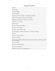
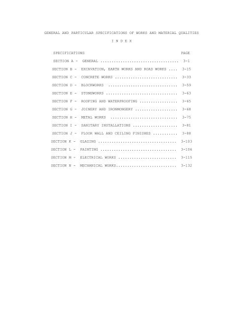
<strong>GENERAL</strong> <strong>AND</strong> <strong>PARTICULAR</strong> <strong>SPECIFICATIONS</strong> <strong>OF</strong> WORKS <strong>AND</strong> MATERIAL QUALITIES<br />
I N D E X<br />
<strong>SPECIFICATIONS</strong><br />
PAGE<br />
SECTION A - <strong>GENERAL</strong> ................................... 3-1<br />
SECTION B - EXCAVATION, EARTH WORKS <strong>AND</strong> ROAD WORKS .... 3-15<br />
SECTION C - CONCRETE WORKS ............................ 3-33<br />
SECTION D - BLOCKWORKS ............................... 3-59<br />
SECTION E - STONEWORKS ................................ 3-63<br />
SECTION F - RO<strong>OF</strong>ING <strong>AND</strong> WATERPRO<strong>OF</strong>ING ................. 3-65<br />
SECTION G - JOINERY <strong>AND</strong> IRONMONGERY ................... 3-68<br />
SECTION H - METAL WORKS .............................. 3-75<br />
SECTION I - SANITARY INSTALLATIONS .................... 3-81<br />
SECTION J - FLOOR WALL <strong>AND</strong> CEILING FINISHES ........... 3-88<br />
SECTION K - GLAZING ................................... 3-103<br />
SECTION L - PAINTING .................................. 3-106<br />
SECTION M - ELECTRICAL WORKS .......................... 3-115<br />
SECTION N - MECHANICAL WORKS........................... 3-132
I N D E X<br />
SECTION A - <strong>GENERAL</strong><br />
Division Titles Page No.<br />
A 1 Scope of work 3 - 1<br />
A 2 Drawings 3 - 1<br />
A 3 Contractor's price 3 - 1<br />
A 4 Use and protection of site 3 - 1<br />
A 5 Materials found on site 3 - 2<br />
A 6 Temporary stormwater drainage 3 - 2<br />
A 7 Shop drawings 3 - 2<br />
A 8 "As - Built" drawings 3 - 3<br />
A 9 Scaffolding 3 - 3<br />
A 10 Protection 3 - 3<br />
A 11 Separate Contracts 3 - 4<br />
A 12 Definitions 3 - 4<br />
A 13 Standards 3 - 5<br />
A 14 Materials generally 3 - 5<br />
A 15 Contractor to verify site measurement 3 - 6<br />
A 16 Samples 3 - 7<br />
A 17 Cutting and patching 3 - 7<br />
A 18 Site offices, Latrines, etc. 3 - 7<br />
A 19 Attendance on the engineer 3 - 8<br />
A 20 Testing 3 - 8<br />
A 21 Temporary buildings 3 - 8<br />
A 22 Temporary works and reinstatement 3 - 8<br />
A 23 Water for the works 3 - 9<br />
A 24 Electricity for the works 3 - 9<br />
A 25 Provision of plant and tools 3 - 10<br />
A 26 Temporary barriers, fencing, etc. 3 - 10<br />
A 27 Inconsistency in contract documents 3 - 10<br />
A 28 Errors in computing contract documents 3 - 11<br />
A 29 Site meetings 3 - 11<br />
A 30 Daily Reports 3 - 11<br />
A 31 Access for the Engineer 3 - 12<br />
A 32 Setting out and levelling 3 - 12<br />
A 33 Programme to be finished 3 - 12<br />
A 34 Cancellation due to slow progress 3 - 12<br />
A 35 Delays 3 - 13<br />
A 36 Non productive time 3 - 13<br />
A 37 Safety, Health and welfare 3 - 13<br />
A 38 Contractors' site Representative 3 - 13<br />
A 39 Attendance 3 - 13<br />
A 40 Official visitors 3 - 13<br />
A 41 Care of the works, etc. 3 - 13<br />
A 42 Work at completion 3 - 14
SECTION<br />
A<br />
<strong>GENERAL</strong><br />
A 1 SCOPE <strong>OF</strong> WORK<br />
These Specifications cover all the works necessary for the<br />
construction of construction of 100 homes/shelters in the West Bank<br />
for those families whose homes have been destroyed due to the conflict<br />
in the Occupied Palestinian Territories. includes testing and<br />
commissioning of all equipment and maintaining the whole works.<br />
A 2 DRAWINGS<br />
A list of Contract Drawing available at the date of tender is<br />
included on the front page of the Drawing Book and at the end of<br />
these Specifications<br />
A 3 CONTRACTOR'S PRICE<br />
The Contractor's price shall include for all materials labour and<br />
plant requirements necessary for the completion of the Contract in<br />
accordance with the Contract Drawing and specifications with<br />
exception only of items supplied by e Employer.<br />
A 4 USE <strong>AND</strong> PROTECTION <strong>OF</strong> SITE<br />
The Contractor shall take such measures and exercise such are to<br />
protect the Site as shown on the Site Plan during the course of the<br />
Works as directed by and to the entire satisfaction of the Engineer.<br />
All temporary buildings and work areas such as Site Offices,<br />
Workshops Store Buildings and Yards, Living Accommodation,<br />
Messrooms, etc. shall be constructed in position approved by the<br />
Engineer.<br />
The contractor shall confine his apparatus, the storage of materials<br />
and the operations of his workmen to limits indicated by law,<br />
ordinances, permits or directions of the Engineer. هTh Contractorٍ<br />
shall erect suitable temporary fences as required by the Engineer.<br />
The Contractor shall not load or permit any part of the structures to<br />
be loaded with a weight that will endanger its safety.<br />
On commencement of the Contract, the Contractor shall clear the Site<br />
and adjacent area of all rubbish and debris to the satisfaction of<br />
the Engineer.
3-1<br />
<strong>SPECIFICATIONS</strong><br />
<strong>GENERAL</strong><br />
USE <strong>AND</strong> PROTECTION <strong>OF</strong> SITE (Cont'd)<br />
Upon completion of the Contract, the Site and any adjacent areas<br />
affected by the building operation shall be properly cleared of all<br />
temporary works, debrisَ نan other rubbish and all disturbed works and<br />
ground made good to the entire satisfaction of the Engineer.<br />
A 5 MATERIALS FOUND ON SITE<br />
Any sand, gravel or other building material found on the Site shall<br />
not be used in the execution of the Works without the prior written<br />
consent of the Engineerٍ which shall not be unreasonably withheld.<br />
A 6 TEMPORARY STORMWATER DRAINAGE<br />
The Contractor shall ensure that the whole of the Site, is kept free<br />
from the risk of stormwater flooding and shall provide such temporary<br />
ditches, gullies نan the like as may be necessary and shall at<br />
completion of the Works backfill such excavation and make good all<br />
works disturbed.<br />
A 7 SHOP DRAWINGS<br />
If at any time before the commencement or during the progress of the<br />
work it appears to the Contractor that for the proper execution of<br />
specific part of the works, shop drawings are necessary, these<br />
drawings shall be prepared by the Contractor and submitted to the<br />
Engineer for approval. On the otherٍhand,the Engineer shall have<br />
authority to order at any time and the Contractor agrees to provide<br />
any number of shop drawings which in the opinion of the Engineerٍare<br />
necessary forٍ the proper execution of a specified work, the<br />
Contractor shall not proceed with the above mentioned work unless<br />
these shop drawings are approved by the Engineer.<br />
Shop drawings shall be fully detailed and drawn to proper scale.<br />
Unless otherwise specifically required in the drawings or<br />
Specifications, shop drawings shall be supplied in four copies with<br />
dark lines on a white background.<br />
Shop drawings shall be approved or returned to the Contractor for<br />
alternation or amendment within four (4) weeks of their receipt by<br />
the Engineer. Shop Drawings returned for alternation or amendment<br />
shall be resubmitted for approval. Altered or amended shop drawings<br />
shall show the nature of the alternation or amendment in a revision<br />
block on the drawings with a revision number or letter and the date<br />
of the revision.
3-2<br />
<strong>SPECIFICATIONS</strong><br />
<strong>GENERAL</strong><br />
A 8 " AS BUILT " DRAWINGS<br />
All prints of the Drawings, where required, shall be corrected by the<br />
Contractor and submitted to the Engineer for approval as the works<br />
proceed. Upon the completion of the Works, the Contractor shall<br />
prepare a completely new set of drawings for the project as executed<br />
and submit same in duplicate to the Engineer for approval.<br />
When approved by the Engineer, the Contractor shall submit one<br />
transparency and six copies of all drawings duly marked "As-Built".<br />
The final payment shall not be made except for the actual works that<br />
have been completed in accordance with the Specifications and have<br />
been duly presented on the "As-Built Drawings".<br />
هTh Contractor shall not be entitled to any extra payment or<br />
extension of time for the correction, preparation and supplying of<br />
the above mentioned drawings and transparencies.<br />
A 9 SCAFFOLDING<br />
The Contractor shall provide, erect, maintain, and dismantle any<br />
clear away at completion proper and adequate scaffolding including<br />
that required for Sub-Contractors and Specialists. Putlong holes<br />
shall be made good to match the adjacent surface as the scaffolding<br />
is dismantle. The Contractor shall be entirely responsible for all<br />
safety precautions in connection with the scaffolding and for its<br />
entire sufficiency for the work.<br />
A 10 PROTECTION<br />
In the pursuance of his obligations under the Conditions of Contract,<br />
the Contractor shall wherever required or directed by the Engineer<br />
cover up and protect the Works form the weather and from damage by<br />
him or other workmen performing subsequent operations. He shall<br />
provide all necessary dustsheets, barriers and guard rails and clear<br />
away هsame at completion.<br />
هTh Contractor shall take all reasonable and proper steps for the<br />
protection of all places on or about the Works, which may be<br />
dangerous to his workmen or any other persons or to traffic. The<br />
Contractor shall provide and maintain warning signs, red warning<br />
lamps and barricades as necessary in all such places.
3-3<br />
<strong>SPECIFICATIONS</strong><br />
<strong>GENERAL</strong><br />
A 11 SEPARATE CONTRACTS<br />
The Employer reserves the right to let other separate contracts in<br />
connection with the work under similar conditions. The Contractor<br />
shall afford other contractors reasonable opportunity for the<br />
introduction and storage of their materials and the execution of<br />
their work, and shall properly connect and co-ordinate his work with<br />
theirs.<br />
If any part of the Contractor's work depends for proper execution or<br />
results upon the work of any other contractor, the Contractor shall<br />
inspect and promptly report to the Engineer and defects in such work<br />
shall render it unsuitable for such proper execution and results.<br />
His failure so to inspect and report shall constitute an acceptance<br />
of the other Contractor's Works as fit and proper for the reception<br />
of this work, except as to defects which may develop in the other<br />
Contractor's work after the execution of his work.<br />
To ensure the proper execution of his subsequent work, the Contractor<br />
shall measure work already in place and shall at once report to the<br />
Engineer any discrepancy between executed work and the Drawings.<br />
A 12 DEFINITIONS<br />
"Approved "directed "selected” means the approval, direction or<br />
selection by the Engineer.<br />
"Instructions means the instructions in writing of the Engineer or<br />
Engineer's Representative unless specified otherwise.<br />
"Manufacturer's Recommendation” means the Manufacturer's<br />
recommendations or instructions, printed or in writing and current at<br />
the date of tender.<br />
“ Or approved equal” means that materials of different manufacturer<br />
may be substituted if proper approval has been obtained. The rates or<br />
prices will be held to be based on the materials specified.<br />
Where an item is denoted as N.I.C. on the Drawings it shall mean that<br />
item indicated is not included in the Contract.<br />
Where the terms Architect or Engineer is used in this Contract they<br />
shall have the same meaning.<br />
Where the terms Architect's Representative or Engineer's<br />
Representative are used they shall have the same meaning.
3-4<br />
<strong>SPECIFICATIONS</strong><br />
<strong>GENERAL</strong><br />
A 13 ST<strong>AND</strong>ARDS<br />
In the Contract reference is made to the Standards, Codes of practice<br />
and Specifications issued by the following organizations, hereinafter<br />
referred to by the following abbreviations:<br />
AASHO Means the American Association of State Highway Officials.<br />
ACI<br />
AFNOR<br />
AISC<br />
ASA<br />
Means the American Concrete Institute.<br />
Means the Association Francaise de Normalisation.<br />
Means the American Institute of Steel Structure.<br />
Means the American Standards Association.<br />
ASHRAE Means the American Society of Heating, Refrigerating and Air-<br />
Conditioning Engineers<br />
ASTM<br />
AWWA<br />
B S<br />
CMA<br />
DIN<br />
ءNEM<br />
NFPA<br />
VDE<br />
Means the American Society for Testing and materials.<br />
Means the American Water Works Association.<br />
Means the British Standards Institution.<br />
Means the Cable Manufacturers Association.<br />
Means the Deutscher Normanusschuss.<br />
Means the National Electrical Manufacturesَ Association.<br />
Means the National Fire Protection Association.<br />
Means the Verban Deutscher Electrotechniker<br />
These references shall in every case be deemed to include the latest<br />
edition or issue of such standards.<br />
The Contractor upon receiving instructions shall supply the<br />
Engineer’s Representative with single copies of all standards<br />
referred to on the Drawings or Specification and shall arrange for<br />
further copies for his own use.
3-5<br />
<strong>SPECIFICATIONS</strong><br />
<strong>GENERAL</strong><br />
A 14 MATERIALS <strong>GENERAL</strong>LY<br />
All materials and manufactured goods are to be the best of their<br />
respective kinds and as described in the Specifications and the<br />
Contractor shall submit for the approval of the Engineer a list of<br />
names and addresses of the manufacturers, the trade marks and types<br />
of all materials and articles he proposes to employ together with all<br />
specifications and descriptions that may be required in this<br />
connection before any orders are placed. Samples are to be provided<br />
if requested by the Engineer. Where a particular proprietary product,<br />
supplier's catalogue is referred to in the Specifications or shown on<br />
the drawings the material specified may be obtained from anotherٍ<br />
source provided it is similar, equal and approved by the Engineer.<br />
If during the course of the Contract certain materials required for<br />
use in the Works should be unobtainable despite the best efforts of<br />
the Contractor, then the Contractor may offer for the approval of the<br />
Engineer substitute materials.<br />
The use of these substitute materials shall be at the sole discretion<br />
of the Engineer.<br />
In the event of the acceptance of the substitute materials a suitable<br />
price reduction shall be made in the respect of decrease in quality<br />
or value but no price addition shall be made in respect of increase<br />
in quality or value.<br />
In the event of refusal of the substitute materials the Contractor<br />
shall not be relieved of any of his obligations under the Contract<br />
and shall be solely liable for any delay or loss occasioned by his<br />
failure to provide materials as specified.<br />
Where manufacturers recommendations have been entered into the<br />
contract documents, it is for the purpose of giving an indications to<br />
the contractor of the Engineer’s intentions on the application and<br />
use of the material.<br />
It is deemed that the successful Contractor will make direct contact<br />
with the manufacturer m to ensure that he is carrying out the works<br />
in accordance with their recommendations.<br />
A 15 CONTRACTOR TO VERIFY SITE MEASUREMENTS<br />
The Contractor shall check and verify all site measurements wherever<br />
requested by other specialist contractors or by nominated or other<br />
sub-contractors to enable the to prepare their own shop drawings, and<br />
pass on the information with sufficient promptness as will not in any<br />
way delay the Works. A copy of all such information passed or shall<br />
be given to the Engineer.
3-6<br />
<strong>SPECIFICATIONS</strong><br />
<strong>GENERAL</strong><br />
A 16 SAMPLES<br />
The Contractor shall furnish for approval, with reasonable promptness<br />
all samples of materials and workmanship required by the Engineer.<br />
The Engineer shall check and approve such samples with reasonable<br />
promptness for conformance with the design concept of the works and<br />
for compliance with the information given in the Contract Documents.<br />
The Work shall be in accordance with approved samples.<br />
a) All material samples shall be delivered to the Engineer’s<br />
office with all charges in connection with therewith paid by<br />
the Contractor.<br />
b) Duplicate final approval samples, in addition to any required<br />
for the Contractor’s use, shall be furnished to the Engineer.<br />
c) Samples shall be furnished so as to delay fabrication allowing<br />
the Engineer reasonable time for consideration of the sample<br />
submitted.<br />
d) Each sample shall be properly labelled with the name and<br />
quality of the material, manufacturer’s name, name of project,<br />
the Contractor’s name and the date of submission and the<br />
Specification number to which the sample refers.<br />
A 17 CUTTING <strong>AND</strong> PATCHING<br />
The Contractor shall be responsible for all cutting, patching<br />
and making good in all trades for all work and his prices will<br />
be deemed to include for all such cutting and patching and<br />
making good.<br />
A 18 SITE <strong>OF</strong>FICES, LATRINES, ETC.<br />
The Contractor shall provide and maintain on the Site for the<br />
duration of the Contract the following: -<br />
a) A temporary office for the accommodation of his Agent/Engineer<br />
and Staff, including all necessary sanitary facilities, such<br />
offices shall be open at all reasonable hours to receive<br />
instructions, notices or other communications. Telephone and<br />
Electric installations shall also be provided.<br />
b) A suitable and adequate temporary office shall be provided and<br />
furnished by the Contractor for the sole use of the Engineer<br />
and his staff. Such office shall be to the approval of the<br />
Engineer.<br />
c) Adequate fire fighting equipment to the approval of the Local<br />
Fire Authority and the Engineer.
d) An approved sign board, written in Arabic and English. The<br />
size of signboard and lettering including to wordings shall be<br />
as directed by the Engineer.<br />
3-7<br />
<strong>SPECIFICATIONS</strong><br />
<strong>GENERAL</strong><br />
A 19 ATTENDANCE ON THE ENGINEER<br />
The Contractor shall for the duration of the Contract supply<br />
sufficient attendance for the Engineer’s supervisory staff and<br />
shall maintain and pay all water, electricity, and telephone<br />
charges shall keep the Site Office and supervision cabins in a<br />
clean and sound condition at all times.<br />
The Contractor shall be responsible for the security of the<br />
Site Office and its contents at all times and shall employ<br />
watchman for this purpose<br />
A 20 TESTING<br />
The Contractor shall allow in his rates and prices for the cost<br />
of carrying our tests necessary for compliance with the<br />
Specification in independent laboratories outside the Site.<br />
A 21 TEMPORARY BUILDINGS<br />
The Contractor shall provide and maintain on the Site sheds,<br />
offices, messrooms, sanitary accommodation and other temporary<br />
works of any kind whatsoever for the Contractor’s supervisory<br />
staff and work people and for Sub-Contractor’s staff employed<br />
upon the works.<br />
The Contractor’s site office shall be open during working hours<br />
to receive instructions notices or other communications.<br />
Sheds shall be suitable to store all materials equipment and<br />
furniture which in the opinion of the Engineer needs protecting<br />
from the weather.<br />
The Contractor shall provide and maintain in approved positions<br />
on the Site Adequate sanitary accommodation for his staff<br />
workmen and sub-Contractors. This sanitary accommodation shall<br />
be kept in a clean and orderly condition to the approval of the<br />
Public Health Authority and the Engineer to ensure that no<br />
nuisance is caused.
3-8<br />
A 22 TEMPORARY WORKS <strong>AND</strong> REINSTATEMENT<br />
<strong>SPECIFICATIONS</strong><br />
<strong>GENERAL</strong><br />
The Contractor shall provide and maintain all temporary roads<br />
and tracks necessary for movement of plant and materials, and<br />
clear same away at completion and make good all works damaged<br />
or disturbed.<br />
The Contractor shall submit drawings and full particulars of<br />
all Temporary Works to the Engineer before commencing same. The<br />
Engineer may required modifications to be made if he considers<br />
them to be insufficient and the Contractor shall give effect to<br />
such modifications but shall not be relieved of his<br />
responsibilities for the sufficiency thereof.<br />
The Contractor shall divert as required, at his coast and to<br />
the approval of the Engineer, all public utilities encountered<br />
during the progress of the Works, except those specially<br />
indicated on the drawings as being included in the Contract.<br />
Where diversions of services are not required in connection<br />
with the permanent Works, the Contractor shall uphold, maintain<br />
and keep the same in working order in existing locations.<br />
The Contractor shall make good, at his own expense, all damage<br />
to telephone, telegraph and electric cable or wires, sewers,<br />
water, or other pipes except where the Public Authority or<br />
Private Party Owing or responsible for the same elects to make<br />
good the damage. The cost incurred in so doing shall be paid by<br />
the Contractor to the Public Authority or Private Party in<br />
demand.<br />
All injury to the surface of the land, to the beds if water<br />
courses, projecting banks, etc. where disturbed by the Works<br />
(other than where specifically ordered by the Engineer) shall<br />
be repaired by the Contractor or the authorities concerned, at<br />
the Contractor’s expense. All such making good shall be to the<br />
approval of the Engineer.<br />
All requirements detailed above shall be provided and<br />
maintained at the expense of the Contractor.<br />
The Employer shall not be liable for loss or injury to and<br />
Temporary Works.<br />
A 23 WATER FOR THE WORKS<br />
The Contractor shall make all necessary arrangements and<br />
provide all water for the proper execution of the Works,
together with all transport temporary plumbing, storage and<br />
distribution, pay all charges and alter adapt and maintain<br />
temporary work as necessary remove and make good at completion.<br />
3-9<br />
A 24 ELECTRICITY FOR THE WORKS<br />
<strong>SPECIFICATIONS</strong><br />
<strong>GENERAL</strong><br />
The Contractor shall make all necessary arrangements and<br />
provide all artificial lighting and power for the proper<br />
execution and security if the Works and its protection.<br />
With all meters temporary wiring and fittings, pay all charges<br />
and alter, adapt and maintain the temporary works as necessary<br />
and remove and make good at completion<br />
A 25 PROVISION <strong>OF</strong> PLANT <strong>AND</strong> TOOLS<br />
The Contractor shall provide and install all necessary hoists,<br />
ladders, scaffolding. Staging, tackles, tarpaulins, tools,<br />
vehicles, and other plant (mechanical and otherwise) and allow<br />
for altering adapting and maintaining them in good condition as<br />
necessary and eventually removing from site and making good.<br />
A 26 TEMPORARY BARRIERS, FENCING ETC...<br />
The Contractor is to provide all temporary barriers, fencing,<br />
hoarding, guard rails, gates, and the like as may be necessary<br />
to protect the public and others, for proper execution of the<br />
Works and shall remove and clear away at completion of the<br />
Works and make good all work disturbed.<br />
A 27 INCONSISTENCY IN CONTRACT DOCUMENTS<br />
The Contractor shall execute the Works according to the<br />
provisions of the Contract Documents. Any work indicated in one<br />
of the documents but omitted and/or stated in one or more of<br />
the other documents shall be treated as though it were included<br />
in all of them.<br />
If any two documents of the Contract conflict as to the quality<br />
of the work to be carried out, the discrepancy shall be brought<br />
to the notice of the Engineer, who shall instruct the<br />
Contractor which of the two conflicting documents to regard as<br />
correct.<br />
If the Contractor should discover that any work has been<br />
omitted and/or not indicated entirely or partially from all the<br />
documents, but that such work is essential to the safety or<br />
proper functioning of the works, he shall report the facts<br />
immediately to the Engineer. If the work is something which in
the opinion of the Engineer could not have been foreseen by an<br />
experienced Contractor, the Engineer should issue to the<br />
Contractor a variation order stipulating the details of the<br />
work to be done.<br />
Save as aforesaid in the above paragraph, no additional payment<br />
shall be made in respect of work carried out in connection with<br />
discrepancies between the various Contract Documents.<br />
3-10<br />
A 28 ERRORS IN COMPUTING CONTRACT DOCUMENTS<br />
<strong>SPECIFICATIONS</strong><br />
<strong>GENERAL</strong><br />
The Contractor shall be responsible for any error which he<br />
makes in computing any quantities of material and labour<br />
required or costs involved or through any lack of knowledge of<br />
the Site or misunderstanding of anything shown or implied on<br />
the Drawings or in the Specifications and/or the Bills of<br />
Quantities.<br />
The Contractor must refer any discrepancy in the Drawings or<br />
the Specifications to the Engineer before proceeding in any of<br />
the Works otherwise the decision of the Engineer as to the<br />
interpretation of the discrepancy will be final. Any item or<br />
items of work not specifically shown on the Drawings or<br />
referred to in the Specifications but which would be necessary<br />
for the proper construction of the works in accordance with the<br />
best practice is implied and must be included for as<br />
incidential to the Contract Sum. Any item for which the<br />
Contractor has not inserted a price in the Bills of Quantities<br />
shall be deemed to be covered by other prices or rates therein.<br />
A 29 SITE MEETINGS<br />
During the course of the Works, site progress meetings shall be<br />
held at regular intervals at least once every two weeks in the<br />
presence of the Engineer for the purpose of co-ordinating the<br />
Contractor’s work and to insure that full compliance with the<br />
various sequences of the contract are maintained. Minutes of<br />
such Site meetings will be recorded, copies will be distributed<br />
to all persons concerned and full effect shall be given to all<br />
instructions contained therein<br />
Prior to such meetings the Contractor shall give to the<br />
Engineer’s representative details in writing of that portion of<br />
the Works he proposes to construct during the coming two weeks<br />
with details of the plant and methods he proposes to employ.<br />
These proposals shall be discussed at the meeting and no work<br />
based on such proposals shall proceed without the approval of<br />
the Engineer’s Representative<br />
The Contractor shall have no claim against the Employer for<br />
costs incurred by him in changing the method of working or in<br />
the provision and use of other additional plant.<br />
A 30 DAILY REPORTS
The Contractor shall deliver daily to the Engineer’s<br />
Representative a report as to the number of workpeople employed<br />
on the Works in each Trade and copies of delivery notes of all<br />
materials and goods to the Site during the day.<br />
3-11<br />
<strong>SPECIFICATIONS</strong><br />
<strong>GENERAL</strong><br />
A 31 ACCESS FOR THE ENGINEER<br />
The Contractor shall provide at all times during the execution<br />
of the Works and the Maintenance Period proper means of access<br />
with ladders, gangways etc., and the necessary attendance to<br />
move and adapt same as directed for the inspection or<br />
measurement of the Works by the Engineer or the Engineer’s<br />
Representative.<br />
A 32 SETTING OUT <strong>AND</strong> LEVELLING<br />
Prior to commencement of any site work the Contractor shall<br />
arrange to record on an approved grid existing site ground<br />
levels and agree with the Engineer’s Representative the<br />
accuracy thereof by preparing a record drawing signed by the<br />
Contractor’s Agent and the Engineer’s Representative. The<br />
Contractor shall set out and level the Works and obtain the<br />
approval of the Engineer’s Representative before commencing<br />
construction.<br />
A 33 PROGRAMME TO BE FURNISHED<br />
The Contractor shall prepare a programme for the Works,<br />
including the work of subcontractors and other work concurrent<br />
with the Contract, using the critical path network method. The<br />
Contractor shall submit three (3) copies of programme to the<br />
Engineer with his tender. Submission of programme will not<br />
relieve the Contractor of his obligations to apply in writing<br />
for instructions as required by the Conditions of Contract.<br />
Receipt of programmes by the Engineer shall neither affect the<br />
Contract completion date no relieve the Contractor of his<br />
responsibility to complete the Works by this date. The<br />
Contractor shall review the programme once each month to take<br />
account of any circumstances which arise affecting the progress<br />
of the Works, and shall produce a revised programme and submit<br />
copies to the Engineer.<br />
A 34 CANCELLATION DUE TO SLOW PROGRESS<br />
If the Engineer shall be of the opinion that having regard to<br />
the state of the Works at any time, the Contractor will be<br />
unable to complete any section of the Works by the time<br />
specified or by such extension thereof as he may be entitled to<br />
under the Contract and the Contractor has failed to carry out<br />
steps and to expedite the work in accordance with the
Conditions of Contract or, if the Engineer is of the opinion<br />
that such steps are inadequate, the Engineer may, by written<br />
order omit the whole or any part of the uncompleted work<br />
included in that section and the Employer shall be at liberty<br />
to execute such omitted work by his own workman or by other<br />
Contractors. If the cost of such omitted or uncompleted work<br />
shall exceed the sum which would have been payable to the<br />
Contractor on the completion of the said work, then the<br />
Contractor shall, upon demand, pay to the Employer the amount<br />
of such excess and it shall be deemed a debt due by the<br />
Contractor to the Employer and shall be recoverable<br />
accordingly.<br />
3-12<br />
<strong>SPECIFICATIONS</strong><br />
<strong>GENERAL</strong><br />
A 35 DELAYS<br />
The Contractor will be deemed to have allowed for all delay<br />
caused by difficulty in obtaining labour and materials or by<br />
suspension of part or the whole of the Works due to adverse and<br />
inclement weather conditions.<br />
A 36 NON-PRODUCTIVE TIME<br />
The Contractor shall allow for all costs incurred by nonproductive<br />
time and all other expenses in connection with<br />
overtime.<br />
A 37 SAFETY, HEALTH <strong>AND</strong> WELFARE<br />
The Contractor shall comply with enactments regulations and<br />
working rules relating to safety health and welfare of<br />
workpeople.<br />
A 38 CONTRACTOR'S SITE REPRESENTATIVE<br />
The Contractor’s Representative in charge of the Works shall be<br />
a duly graduated Engineer having at least Three (3) years<br />
experience in the superintendence of similar works and shall be<br />
required to have a proper command of the Arabic and English<br />
languages.<br />
A 39 ATTENDANCE<br />
The Contractor shall allow for and be responsible for the<br />
general attendance of one trade upon another.<br />
A 40 <strong>OF</strong>FICIAL VISITORS<br />
The Contractor shall at all times when authorized by the<br />
Engineer give free undisputed access and all facilities to any<br />
authorized employee of the Employer, any representative of the<br />
U.N.D.P. or any person authorized by the U.N.D.P. wishing to<br />
view or inspect any part of the Works or the materials to be<br />
incorporated therein.
A 41 CARE <strong>OF</strong> THE WORKS, ETC.<br />
The Contractor shall keep all persons (including those employed<br />
by Sub-Contractors) under control and within the boundaries of<br />
the Site. He will be held responsible for the care of the<br />
existing premises and of the works generally until their<br />
completion, including all work executed and materials, good and<br />
plant (including those Sub-Contractors and Suppliers)deposited<br />
on the Site; together with all risks arising from the weather,<br />
carelessness of work people, damage or loss by theft or any<br />
other cause; and he shall make good at his own expense or such<br />
damage and lose.<br />
A 42 WORK AT COMPLETION<br />
3-13<br />
<strong>SPECIFICATIONS</strong><br />
<strong>GENERAL</strong><br />
The Contractor shall clean the Works thoroughly inside and out<br />
removing all splashes, deposits, rubbish and surplus material.<br />
The Contractor shall remove all temporary markings, coverings<br />
and protective rappings unless otherwise instructed.<br />
The Contractor shall touch up minor faults in painted surfaces<br />
carefully matching colour and brushing out edges. He shall<br />
repaint badly marked areas back to suitable breaks and<br />
junctions.<br />
The Contractor shall adjust, ease and lubricate all doors,<br />
windows, drawers hardware, equipment, appliances controls and<br />
other moving parts as necessary to ensure easy and efficient<br />
operations.<br />
The Contractor shall leave the Works secure with all access<br />
locked. He shall account for all keys and shall hand over to<br />
the Employer with itemized schedule signed by the Employer as<br />
receipt.
3-14<br />
I N D E X<br />
______________<br />
SECTION B - EXCAVATION, EARTH WORKS <strong>AND</strong> ROAD WORKS<br />
Division Titles Page No.<br />
B - 1 General 3 - 15<br />
B - 2 Soil Information 3 - 15<br />
B - 3 Materials 3 - 15<br />
B - 4 Site Preparation 3 - 16<br />
B - 5 Setting out 3 - 17<br />
B - 6 Excavation 3 - 17<br />
B - 7 Planking and Structting 3 - 18<br />
B - 8 Keeping Excavation Free From Water 3 - 18<br />
B - 9 Storing Of Suitable Excavated Material 3 - 19<br />
B - 10<br />
Disposal of unsuitable and surplus excavated<br />
material. 3 - 19<br />
B - 11 Excavation For Foundation 3 - 19<br />
B - 12 Excavation For Trenches 3 - 19<br />
B - 13 Backfill And Fill 3 - 21<br />
B - 14 Bed Of Hardcore 3 - 21<br />
B - 15 Placing Of Agricultural Soil, Gravel 3 - 21<br />
B - 16 Excavation Of Cuttings in Carriage Way 3 - 22
B - 17<br />
B - 18<br />
Filling And Forming Of Embankments and<br />
other areas of fill. 3 - 22<br />
Compaction Of Embankments and other<br />
areas of fill 3 - 23<br />
B - 19 Road Works 3 - 25<br />
S E C T I O N<br />
B<br />
EXCAVATION - EARTH WORKS <strong>AND</strong> ROAD WORKS<br />
B 1<br />
<strong>GENERAL</strong><br />
The Contractor shall carry out all excavations, filling,<br />
backfilling and all other earthworks required in whatever<br />
material may be encountered.<br />
The Works shall be executed accurately to the dimensions,<br />
levels, lines and profiles as indicated on the drawings<br />
or directed by the Engineer.<br />
The Contractor shall reconstruct to the proper level and<br />
profile any filled areas which settle or spread during<br />
the execution of the work or during the maintenance<br />
period.<br />
The Contractor shall drain and dewater the underground<br />
water to a level below the excavation by lowering the<br />
water table with a proper drainage and dewatering system<br />
approved by the Engineer.<br />
B 2<br />
SOIL INFORMATION<br />
The Contractor shall be deemed to have visited the Site<br />
of Works and satisfied himself as to the nature of the<br />
ground and made himself conversant with the local<br />
conditions to be encountered during the execution of the<br />
Contract. The con-tractor is requested to perform a soil<br />
test to determine the nature and bearing capacity of the<br />
soil surface as directed by the Engineer.<br />
B 3<br />
B 3.01<br />
MATERIALS<br />
Backfill and Fill<br />
Backfill and fill shall be a structurally sound material<br />
such as: less than 1 gravel or native soil free of rocks,<br />
lumps, vegetables and other organic materials obtained
from suitable excavated material and/or from approved<br />
borrow pits.<br />
B 3.02<br />
Water<br />
Water shall be clean potable water as specified under<br />
“Concrete Work”<br />
B 3.03<br />
Concrete<br />
Concrete used as fill for making up the correct level<br />
areas of over-excavation shall be, where required by the<br />
Engineer of Class "B" as specified under "Concrete Work".<br />
3-15<br />
<strong>SPECIFICATIONS</strong><br />
EXCAVATIONS<br />
B 3.04<br />
Hardcore<br />
Hard-core under floor paving, etc... ) (Where shown on the<br />
drawings or as directed by the Engineer) shall consist of<br />
tough, sound and durable rubble stones (maximum 150mm),<br />
free from coatings, drys, seems or flows of any<br />
character. Fine aggregate for blinding the interstices of<br />
hard-core bed shall be as described in “Concrete Work”.<br />
B 3.05<br />
Agricultural Soil, Gravel and Sand Fill<br />
Agricultural soil shall be first choice top soil rich in<br />
organic materials and free from roots, stones and rubbish<br />
suitable for plantation and shall be obtained from an<br />
approved source. Gravel fill shall consist of graded<br />
gravel 50mm. Down to 20mm. And blinded with clean coarse<br />
sand.<br />
B 4<br />
B 4.01<br />
SITE PREPARATION<br />
Existing Public Utilities<br />
The Contractor shall ascertain the whereabouts of all<br />
existing public utilities on the site, both above and<br />
below ground. Such utilities shall be removed, sealed or<br />
rerouted in a manner prescribed by the Public Authorities<br />
concerned at the Contractor’s own expense. The Contractor<br />
shall also be held responsible for all damages entailed<br />
on any of the public utilities adjacent to the Site<br />
resulting from the Works.<br />
B 4.02<br />
Removal of Existing Structures and Other Obstructions<br />
This work shall include, but not be limited to, the<br />
removal of existing structures and other obstructions<br />
interfering with the Works. The Salvaging of any of these<br />
materials for the use of the Employer shall be as
directed by the Engineer and unwanted materials shall be<br />
disposed off the Site in a satisfactory Manner at the<br />
Contractor’s expense.<br />
B 4.03<br />
Cleaning and Grubbing<br />
The Contractor shall perform the clearing and grubbing<br />
(if any) of top soil consisting mainly of loose soil,<br />
vegetable and organic matters, drift sand, unsuitable<br />
soil and rubbish by scarifying the areas to be excavated<br />
and side-walks to a minimum depth of 300mm from the<br />
natural ground level. All materials resulting from the<br />
above operations shall be removed from the Site, loaded<br />
and transported and off loaded spread and levelled to<br />
approved dumps as directed by the Engineer.<br />
3-16<br />
<strong>SPECIFICATIONS</strong><br />
EXCAVATIONS<br />
B 5<br />
SETTING-OUT<br />
The Contractor shall stakeout the work as shown on the<br />
Drawings and secure the Engineer’s approval of his<br />
stakeout before proceeding with construction. If, in the<br />
opinion of the Engineer, modification of the line or<br />
grade is advisable before or after stake-out the Engineer<br />
will issue detailed instructions in writing to the<br />
Contractor for such modification and the Contractor shall<br />
revise the stake-up for further approval in accordance<br />
with the relevant Clause of the Conditions of Contract.<br />
B 6<br />
B 6.01<br />
EXCAVATION<br />
General<br />
Excavation in any material whatsoever found including<br />
rock to reduce levels and to form foundations, bases,<br />
trenches, septic tanks, cesspools, pits and the like to<br />
depths shown on the drawings or as directed by the<br />
Engineer.<br />
Completely remove all existing obstructions in the line<br />
of excavations such as wall, slabs, curbs, steps and the<br />
like.<br />
Trim excavations to required profiles and levels. Remove<br />
all loose material.<br />
Level and well ram and consolidate surface of ground and<br />
bottom of all excavations to receive concrete<br />
foundations, beds, etc.<br />
Bottoms of excavations shall be approved by the<br />
Engineer’s
Representative before any concrete is laid.<br />
Should the Contractor excavate deeper than is shown on<br />
the drawings or required by the Engineer’s Representative<br />
to obtain a solid bottom he must fill up excavation to<br />
the proper level with concrete Class B at his own<br />
expense.<br />
B 6.02<br />
Excavation in Rock<br />
Rock shall be defined as boulders, exceeding 0.25m3 in<br />
volume or any kind of stone or rock formation which in<br />
the opinion of the Engineer’s Representative requires for<br />
its removal drilling and blasting wedging, sledging or<br />
barring or breaking up with power-operated hard tool..<br />
The definition shall exclude any soft or disintegrated<br />
rock which can be removed with a hard pick or mechanical<br />
excavator or shovel or loose, shaken or previously<br />
blasted rock or broken stone in rock fillings or<br />
elsewhere.<br />
3-17<br />
<strong>SPECIFICATIONS</strong><br />
EXCAVATIONS<br />
Blasting by explosives shall not be permitted without<br />
obtaining the written approval of the Engineer. If such<br />
approval is given the Contractor shall be solely<br />
responsible for:-<br />
1 - Obtaining permits, keeping record.<br />
2 - Storing permits, keeping record.<br />
3 - Taking all necessary precautions in compliance with<br />
the regulations pertinent to the use of Explosives.<br />
4 - Any damage that may occur due to the blasting<br />
operations where rock is encountered it shall be<br />
carefully excavated and the Contractor shall not be<br />
entitled to additional compensation unless<br />
otherwise specified in the Bills of Quantities.<br />
B 7<br />
PLANKING <strong>AND</strong> STRUTTING<br />
The terms “planking and strutting” will be deemed to<br />
cover whatever methods the Contractor elects to adopt for<br />
shoring the sides of excavation and also for planking and<br />
strutting the excavations against the sides of adjoining<br />
buildings, public roadways, etc… The Contractor will be<br />
held responsible for shoring the sides of all<br />
excavations, adjoining building and the like and no claim<br />
for additional excavation, concrete or other material or<br />
workmanship will be considered in this respect.<br />
In the event of any collapse occurring the excavations,<br />
the Contractor shall re-excavate and re-instate such<br />
excavations at his own expense. No additional excavations<br />
will be paid or should the Contractor batter the sides of<br />
the excavations.<br />
B 8<br />
KEEPING EXCAVATIONS FREE FROM WATER
All excavations shall be kept clear of water by pumping<br />
or bailing or by well-point dewatering, but the latter<br />
system shall not be employed if any danger exists of<br />
withdrawing water from the foundations of the adjoining<br />
buildings and such water shall be discharged clear of the<br />
works and the method adopted shall in no way contravene<br />
the regulations of the Local Authorities.<br />
The system or systems to be employed shall be approved by<br />
the Engineer. Such approval if given shall not waive the<br />
Contractor’s responsibilities and liabilities under the<br />
Contract.<br />
Particular attention shall be paid to the installation of<br />
sheeting and shoring as may be necessary for the<br />
protection of the work and for the safety of personnel<br />
and public.<br />
3-18<br />
<strong>SPECIFICATIONS</strong><br />
EXCAVATIONS<br />
B 9<br />
STORING <strong>OF</strong> SUITABLE EXCAVATED MATERIAL<br />
During excavation, materials suitable for backfill and<br />
fill shall be stockpiled on the Site at sufficient<br />
distance from the sides of the excavation to avoid overloading<br />
and prevent caveins or mixing with the concrete<br />
during the construction of foundations.<br />
B 10<br />
DISPOSAL <strong>OF</strong> UNSUITABLE <strong>AND</strong> SURPLUS EXCAVATED MATERIAL<br />
Upon the order of the Engineer, all unsuitable and<br />
surplus excavated materials shall be immediately removed.<br />
Loaded and transported off the site area by the<br />
Contractor to approved dumps and he shall abide by the<br />
relevant local regulations.<br />
B 11<br />
EXCAVATION FOR FOUNDATIONS <strong>AND</strong> SUB-STRUCTURE<br />
The Contractor shall excavate to reach a suitable strata<br />
accepted by the Engineer or as shown by the Drawings<br />
during excavation for foundations, the bottom layer of<br />
excavation of minimum 200mm in thickness, shall be left<br />
undisturbed and subsequently removed manually only when<br />
the concrete in blinding is about to be placed in order<br />
to avoid softening or deterioration of the surfaces of<br />
the excavation.<br />
Bottom of all excavations shall be formed to correct<br />
levels as shown on the Drawings or as directed in writing
y the Engineer and shall be trimmed, levelled and well<br />
cleaned before pouring and concrete.<br />
In the event of the contractor excavating deeper than the<br />
levels required, he shall make the difference between<br />
levels with concrete class “B” at his own expense.<br />
After each excavation is complete, the Contractor shall<br />
notify the Engineer to that effect, and no concrete shall<br />
be placed until the Engineer has approved the excavation<br />
and the character of the foundation material.<br />
B 12<br />
B 12.O1<br />
EXCAVATION FOR TRENCHES<br />
General<br />
The Contractor shall provide all forms and bracings, and<br />
excavate trenches necessary to install all drainage,<br />
sewer water supply, electrical and telephone cables to<br />
the lines and grades complete in strict conformity with<br />
these specifications, applicable drawings and/or as<br />
directed by the Engineer.<br />
3-19<br />
<strong>SPECIFICATIONS</strong><br />
EXCAVATIONS<br />
B 12.O2<br />
Grading<br />
The bottom of the trenches shall be accurately graded to<br />
provide uniform bearing and support for each section of<br />
the pipe on undisturbed soil at every point along its<br />
length, except for the portions of the pipe where it is<br />
necessary to excavate for bell-holes and for proper<br />
sealing of joints. Bell-holes and depressions for joints<br />
shall be dug after the trench has been graded.<br />
Share shall be taken not to excavate below the depths<br />
indicated. Where rock shall be excavated to the required<br />
depth. Uneven surface of the bottom trench shall be<br />
excavated 15mm deeper. Such depth, if in rock, shall be<br />
back-filled with concrete Class “B” as specified under<br />
“Concrete Work” and when in earth, shall be back-filled<br />
with approved sand at the Contractor’s own expense.<br />
Whenever unstable soil, which in the opinion of the<br />
Engineer, is incapable of properly supporting the pipe or<br />
duct is encountered in the bottom of the trench, such<br />
soil shall be removed to the depth required and the<br />
trenchy back-filled to the proper grade with sand, fine<br />
gravel or other suitable material approved by the<br />
Engineer.<br />
The width of the trench for Drainage at and below the top<br />
of the pipe shall be such that the clear space between
the barrel of the pipe and the trench wall shall be 20mm<br />
on each side of the pipe. The width of the trench above<br />
that level may be as wide as necessary for sheeting and<br />
bracing and the proper performance of the work.<br />
Trench for Water Supply System shall be of a depth to<br />
provide minimum cover over the top of 300mm and avoid<br />
interference of water lines with other utilities. Width<br />
of trench shall be a maximum of 200mm on each side of the<br />
pipe.<br />
The width of trenches for electrical and telephone cables<br />
shall be as specified in their relative section. Banks<br />
may be sloped or widened to facilitate placement of<br />
cables, but not to an extend that will cause interference<br />
with other utilities.<br />
Excavation for appurtenant structures for manholes,<br />
septic tank, percolating pit and similar structures shall<br />
be sufficient to allow a minimum of 300mm of clear space<br />
between their outer surfaces shoring timbers which may be<br />
used to protect the banks.<br />
3-20<br />
<strong>SPECIFICATIONS</strong><br />
EXCAVATIONS<br />
B 13<br />
BACKFILL <strong>AND</strong> FILL<br />
Approved suitable excavated material as specified under<br />
“MATERIALS” shall be used in the backfilling and filling<br />
next to footings, foundations underground structures,<br />
under sub-floors, etc... and shall be laid in layers not<br />
exceeding 200mm and compacted with compaction equipment,<br />
as approved by the Engineer. Moisture content shall be<br />
adjusted as directed by the Engineer and 95% of dry<br />
weight compaction accordance to ASTM: D1557-70 shall be<br />
achieved.<br />
Should the quantity of the excavated material be not<br />
sufficient for the process of backfill and fill, the<br />
Contractor shall obtain the quantity required of such<br />
backfill and fill from approved borrow pits and transport<br />
same to the Site of work at his own expense.<br />
No backfill shall be executed until the footings,<br />
foundations, etc., have been inspected, measured and<br />
approved by the Engineer.<br />
Trenches should be backfilled until all required tests<br />
are performed and until the Engineer has verified that<br />
the Utility systems have been installed in accordance<br />
with the
Specifications and the Drawings. The backfill in the pipe<br />
zone must be placed and completed so as to provide and<br />
maintain adequate and even support around the pipe wall.<br />
If mechanical compaction equipment is need, care must be<br />
taken to prevent direct contact with the pipe.<br />
B 14<br />
BED <strong>OF</strong> HARDCORE<br />
The bed of hard-core, where shown on the Drawings or as<br />
directed by the Engineer shall be of an approved rubble<br />
stone as specified under “MATERIALS” and shall be laid<br />
under floor pavings. The rubble stone for hard-core shall<br />
be hand-packed with sharp edge upward and wider (natural<br />
face) laid on the ground. The interstices of hard-core<br />
bed shall be filled with approved fines, wetted<br />
sufficiently and well consolidated. The thickness of the<br />
hard-core bed shall be as shown on the Drawings.<br />
B 15<br />
PLACING <strong>OF</strong> AGRICULTURAL SOIL, GRAVEL <strong>AND</strong> S<strong>AND</strong><br />
The agricultural sifted soil as specified under<br />
“MATERIALS” shall be spread in the flower boxes and beds<br />
to the thickness shown on the Drawings after thorough<br />
watering and on a bed of 100mm thick graded gravel<br />
blinded with clean coarse sand to the satisfaction of the<br />
Engineer.<br />
3-21<br />
<strong>SPECIFICATIONS</strong><br />
EXCAVATIONS<br />
B 16<br />
EXCAVATIONS <strong>OF</strong> CUTTINGS IN CARRIAGE WAYS<br />
1- Hauling of material from cuttings or borrow pits to<br />
the embankments or other areas of fill shall<br />
proceed only when sufficient compaction plant is<br />
operating at the place of disposition to ensure<br />
compliance with the requirements of specifications.<br />
2- Any excess depth excavated below formation level<br />
tolerance shall be made good by back filling with<br />
suitable material of similar characteristics to<br />
that removed, compacted in accordance with<br />
specification.<br />
3- The slopes of cuttings shall be cleared of rock<br />
fragments which move when prized by a crow bar.<br />
4- Construction traffic shall not use the surface of<br />
the bottom of a cutting unless the cutting is in<br />
rock or the Contractor maintains the level of the<br />
bottom surface at least 30cm above formation level.<br />
Any damage to the sub-grade arising from such use<br />
of the surface shall be made of good by the<br />
Contractor at his own expense, with material having<br />
the same characteristics as the material which has<br />
been damaged.
B 17<br />
FILL<br />
FILLING <strong>AND</strong> FORMING <strong>OF</strong> EMBANKMENTS <strong>AND</strong> OTHER AREAS <strong>OF</strong><br />
1- Embankments and other areas of fill shall be formed<br />
of material defined as “ suitable material”.<br />
2- All earthworks material placed in or below<br />
embankments, below formation level in cuttings or<br />
else wherein the works shall be deposited and<br />
compacted as soon as practicable after excavation<br />
in layers of thickness appropriate to the<br />
compaction plant used or as a permitted departure<br />
therefrom. Embankments shall be built up evenly<br />
over the full width and shall be maintained at all<br />
times with a sufficient camber and a surface<br />
sufficiently even to enable surface water to drain<br />
readily from them. During the construction of<br />
embankments, the Contractor shall control and<br />
direct constructional traffic uniformly over their<br />
full width. Damage to compacted layers by<br />
constructional traffic shall be made good by the<br />
Contractor.<br />
3- In areas of shallow filling where after removal of<br />
topsoil the ground level is within 30cccm of<br />
formation level constructional traffic shall not<br />
use the surface unless the Contractor brings up and<br />
maintains the surface level at least 30cm above<br />
formation level. Any damage to the sub-grade<br />
arising from such use shall be made good by the<br />
Contractor at his own expense with material having<br />
the same characteristics as the damaged materials.<br />
3-22<br />
<strong>SPECIFICATIONS</strong><br />
EXCAVATIONS<br />
B 18<br />
COMPACTION <strong>OF</strong> EMBANKMENTS <strong>AND</strong> OTHER AREAS <strong>OF</strong> FILL<br />
1- All materials used in embankments and as filling<br />
elsewhere shall be compacted as soon as practicable<br />
after deposition.<br />
2- Variation from the method of compaction stated<br />
below or the use of plant not included therein will<br />
be permitted only if the Contractor demonstrates at<br />
site trials that a state of compaction is achieved<br />
by the alternative method equivalent to that<br />
obtained using the approved methods. This procedure<br />
shall be agree and approved by the Engineer.<br />
3- The Engineer may at any time carry out comparative<br />
field density tests determined in accordance with<br />
S. S. 1377 test No. 14 on material, which he<br />
considers has been, inadequately compacted. If the<br />
test results when compared with the results of<br />
similar tests made on adjacent approved work in<br />
similar materials carried out in accordance with<br />
specification, show the state of compaction to be<br />
inadequate and this held to be due to failure of<br />
the Contractor to comply with the requirements of
the Contract, the Contractor shall carry out such<br />
further work as the Engineer may decide is required<br />
to comply with the terms of the Contract.<br />
3-23<br />
<strong>SPECIFICATIONS</strong><br />
EXCAVATIONS<br />
5- The Contractor shall not less than 24 hours before<br />
he proposes to carry out compaction processes<br />
during periods of overtime, apply in writing to the<br />
Engineer for permission to do so.<br />
B 19<br />
B 19.01<br />
ROAD WORKS<br />
OVERALL REQUIREMENTS<br />
A) Horizontal alignments, surface levels and surface<br />
regularity of pavement courses:<br />
1- Horizontal alignments shall be determined<br />
from one edge of the carriage way pavement<br />
surface as shown on the Drawings. The edge of<br />
the carriageway as constructed and all other<br />
parallel alignments shall be correct within a<br />
tolerance of 15mm there from.<br />
2- The levels of pavement courses shall be<br />
determined from the true pavement surface,<br />
which shall be the surface of the wearing
course from flexible pavements calculated<br />
from the carriage way vertical profile and<br />
cross falls as sown on the Drawings. The<br />
vertical depth below the true pavement<br />
surface at any point on the constructed<br />
surface of the formation or pavement courses<br />
shall be within the appropriate tolerances<br />
stated below:<br />
Base course tolerance = __ 10 mm<br />
Road base tolerance = __ 15 mm<br />
Sub-base tolerance = __ 20 mm<br />
Formation tolerance = __ 25 mm<br />
3- The surface level of the laid wearing course<br />
shall not deviate vertically at any point<br />
from the true pavement surface by more than<br />
10mm.<br />
4- For checking compliance with the above<br />
tolerances, measurements of surface levels<br />
will be taken at a grid of points 20 meter<br />
centers longitudinally and at 2 meter centers<br />
trans-versely starting one meter from the<br />
edge of the carriage way.<br />
5- Compliance with tolerance shall be tested by<br />
rolling straight edge, operated parallel to<br />
the center line of the carriage way and one<br />
meter from the near side edge of each lane of<br />
carriage way.<br />
3-25<br />
<strong>SPECIFICATIONS</strong><br />
EXCAVATIONS<br />
6- For lengths less than 100 meter the laid<br />
pavement surface and the surface of the base<br />
course shall be tested with a 4 meter<br />
straightedge placed parallel to the<br />
centerline of the road. The laid pavement<br />
surface and the surface of the base course<br />
shall have no greater depression under the<br />
straightedge than 10mm and 10mm respectively.<br />
7- Where any tolerance is exceeded the<br />
Contractor shall determine the full extent of<br />
the area which is out of tolerance and shall<br />
make good by rectifying the surface of the<br />
pavement course or formation in the manner<br />
described below:<br />
a- Formation level:<br />
If the surface is too high it shall be<br />
re-trimmed and re-compacted. If the<br />
surface is too low the deficiency shall<br />
be corrected by the addition of fresh
suit-able material of the same<br />
classification laid and compacted to<br />
specification.<br />
b- Roadbases and Sub-bases:<br />
Where this consist of unbound material<br />
the top shall be scarified, reshaped,<br />
with added material as necessary, and<br />
recompacted all to specification. The<br />
area treated shall normally be not less<br />
than 30 meter long and 2.5 meter wide<br />
or such less length to be determined by<br />
the Engineer as necessary to obtain<br />
compliance with specification.<br />
B) Use of surfaces by constructional traffic:<br />
1- Constructional traffic used on pavement under<br />
construction shall be suitable in relation to<br />
the thickness of the courses it traverses so<br />
that damage is not caused to sub-grade or the<br />
material already constructed.<br />
2- The wheels or tracks of plant moving over the<br />
various pavement courses shall be kept from<br />
deleterious materials.<br />
C) Transporting, laying and compacting of road<br />
pavement materials containing Tar or Bitumen<br />
Binder.<br />
1- Bituminous materials shall be transported in<br />
clean vehicles and shall be covered over when<br />
in transit or a waiting tripping. The use of<br />
dust,<br />
Oil or water in the interior of the vehicles<br />
to facilitate discharge of the mixed<br />
materials is permissible but the amount shall<br />
be kept to a minimum and excess shall be<br />
removed by tipping or brushing.<br />
3-26<br />
<strong>SPECIFICATIONS</strong><br />
EXCAVATIONS<br />
2- The mixed material shall as soon as possible<br />
after arrival at the site be supplied<br />
continuously to the paver and laid without<br />
delay. The rate of delivery of material to<br />
the paver shall be so regulated as to enable<br />
the paver to be operated continuously and it<br />
shall be so operated whenever practicable<br />
3- The rate of travel of the paver and its<br />
method of operation shall be adjusted to<br />
ensure an oven and uniform flow of material<br />
across the full laying width, freedom from<br />
dragging or tearing of the material and<br />
minimum segregation.<br />
4- The material shall be laid generally in<br />
conformity with the recommendations for<br />
laying in the British Standard to which it<br />
has been made.
5- Hand laying of any bituminous material will be<br />
permitted only in the following<br />
circumstances:<br />
a. For laying regulating courses of<br />
irregular shape and varying thickness.<br />
b. In confined spaces where it is<br />
impracticable for a paver to operate.<br />
c. For footways.<br />
6- Material shall be compacted as soon as<br />
rolling can be effected without causing undue<br />
displacement of the mixed material and while<br />
this has at least the minimum rolling<br />
temperature stated in the appropriate British<br />
Standard. The material shall be uniformly<br />
compacted by an 8-10 tons smooth wheel roller<br />
having a width of roll not less than 45cm, or<br />
by a mult-wheeled pneumatic tyred roller of<br />
equivalent weight except that wearing course<br />
and base course material shall be surface<br />
finished with a smooth wheel roller.<br />
7- The material shall be rolled in a<br />
longitudinal carriageway over lapping on<br />
successive passes by at a pneumatic tyred<br />
roller, at least the nominal width of the<br />
tyre.<br />
8- Hand-raking of wearing course material which<br />
has been laid by a paver and the addition of<br />
such material by handspreading to the paved<br />
area for adjustment of level will be<br />
permitted only in the following<br />
circumstances:<br />
a- At the edges of the layers of material<br />
and at gullies and manholes.<br />
b- Where other wise directed by the<br />
Engineer.<br />
3-27<br />
<strong>SPECIFICATIONS</strong><br />
EXCAVATIONS<br />
9- Rollers shall not stand on newly laid<br />
material while there is a risk that it will<br />
be deformed thereby.<br />
10- a. By heating the joint with an approved<br />
joint heater at the time when the<br />
additional width is being laid but<br />
without cutting back or coating with<br />
binder. The heater shall raise the<br />
temperature of the full depth or the<br />
wearing course to figure within the<br />
rolling temperature range specified for<br />
the material and for a width not less<br />
than 75mm on each side of the joint. In<br />
this case, however the Contractor shall<br />
have available for use in the event of<br />
breakdown, equipment necessary for<br />
operating method (c).
. By using two or more pavers operating<br />
in echelon where there is practicable<br />
and in sufficient proximity for<br />
adjacent widths to be fully compacted<br />
by continuous rolling or by using a<br />
multiple-lane-width payer.<br />
c. By cutting back the exposed joints to a<br />
vertical face of not less than the specified<br />
thickness, discarding all<br />
loosened material and cooling the<br />
vertical face completely with a grade<br />
of hot tar or hot bitumen suitable for<br />
the purpose before the next width is<br />
laid.<br />
11- Base course material shall not remain<br />
uncovered by either the wearing course or<br />
surface treatment whichever is specified in<br />
the Contract for more than 3 consecutive days<br />
after being laid.<br />
B 19.02<br />
SUB-BASE <strong>AND</strong> ROAD BASE<br />
A. Constructions requirements for materials of base<br />
and sub-grade.<br />
1- Transport vehicles carrying plant mixed<br />
mater-ial shall have a capacity suited to the<br />
output of the mixing point and the site<br />
conditions and be capable of discharging<br />
cleanly. Material when mixed shall be removed<br />
at once from the mixer, transported directly<br />
to the point where it is to be laid and<br />
protected from the weather both during<br />
transit from the mixer to the laying size and<br />
whilst tripping.<br />
3-28<br />
<strong>SPECIFICATIONS</strong><br />
EXCAVATIONS<br />
2. All material shall be placed and spread<br />
evenly. Spreading shall be undertaken either<br />
concurrently with placing or without delay.<br />
Roadbase material shall be spread using a<br />
paving machine or spreader box operated with<br />
a mechanism which levels off the material to<br />
an even depth. Except where otherwise<br />
specified in individual clauses, the material<br />
shall be spread in one layer so that after<br />
compaction the total thickness is as<br />
specified.<br />
3- Compaction shall be completed as soon as<br />
possible after the material has been spread.
4- Special care shall be taken to obtain full<br />
compaction in the vicinity of both<br />
longitudinal and transverse.<br />
5- The surface of any layer of material shall be<br />
on completion of compaction be well closed,<br />
free from movement under compaction plant and<br />
from compaction planes, ridges, cracks or<br />
loose material. All loose, segregated or<br />
otherwise defective areas shall be made good<br />
to the full thickness of layer and recompacted.<br />
6- Compaction shall be carried out by the method<br />
specified in the table page ().<br />
B) Granular sub-base and Road Material:<br />
1- It shall comprise natural sands, gravels,<br />
crushed rock. The material shall be well<br />
graded and lie within the following grading<br />
limits:<br />
B.S. Sieve Size<br />
passing<br />
Percentage by weight<br />
3 in 100<br />
1 1/2 in 85 - 100<br />
3/8 in 45 - 100<br />
3/16 in 25 - 85<br />
No. 25 8 - 45<br />
No. 200 0 - 10<br />
The particle size shall be determined in<br />
accordance with B.C. 1377.<br />
2- The material passing no. 36B.S. sieve, when<br />
tested in accordance with B.S. 1377 shall<br />
have a plasticity index of less than 6.<br />
3-29<br />
<strong>SPECIFICATIONS</strong><br />
EXCAVATIONS<br />
3- The material shall be laid and compacted to<br />
the requirements of specifications at a<br />
moisture content within the range one percent<br />
above to 2 percent below the optimum<br />
percentage determined in accordance with<br />
vibrating hammer method test in B.S. 1377<br />
4- On completion of roadbase and until any<br />
surfacing is laid on it, the finished surface<br />
shall be maintained free from potholes, ruts<br />
and undulations, irregularities depressions,<br />
loose material or other defects.
5- Paved hard shoulders shall be constructed of<br />
the materials and to the dimensions described<br />
in the contract. Alternatively if agreed by<br />
the Engineer the Contractor may construct<br />
hard shoulders to the same specification as<br />
the carriage way pavement.<br />
B 19.03<br />
FLEXIBLE SURFACING<br />
A) Rolled Asphalt for Base:<br />
1- This material shall be made in accordance with the<br />
requirements of B,S, 594for base course mixtures<br />
subject to the under mentioned proviso relating to<br />
blastfurnace slag. It shall be laid and compacted<br />
to relevant clauses.<br />
2- Coarse aggregate content 65 percent. When the bulk<br />
density of the slag coarse aggregate is less than<br />
80lb per cubic foot, the coarse aggregate content<br />
shall be reduced to 55 per cent.<br />
3- Petroleum bitumen in accordance with B.S. 594 of<br />
penetration as described in the contract.<br />
B) Rolled Asphalt Wearing Coarse:<br />
1- Rolled asphalt wearing coarse shall be in<br />
accordance with the general requirements of<br />
B.S.594.<br />
2- Asphaltic Cement:<br />
a. Equal proportions by weight of petroleum<br />
bitumen of appropriate penetration and refind<br />
asphalt or/<br />
b. Pitch/Bitumen to the following<br />
specifications: A mixture of 75-80 percent of<br />
petroleum bitumen with 20-25 percent of a<br />
coal tar pitch produced by straight running<br />
predominately from a vertical retort crude<br />
source.<br />
3-30<br />
<strong>SPECIFICATIONS</strong><br />
EXCAVATIONS<br />
The softening point of the pitch shall lie<br />
between 55 C and 80 C and the petroleum<br />
bitumen shall have a penetration conforming<br />
to the requirements of B.S.594 tables 1, 2 or<br />
3 as described in the Contract. The Engineer<br />
may require, from time to time, certificates<br />
confirming that the mixture has a salability<br />
index not higher than 1.2 when tested<br />
according to the method described in the Road<br />
Research Laboratory Research Note No.<br />
RN/4112. The use of density-gradient column
in a storage stability test for pitch/bitumen<br />
mixtures; or<br />
c. Petroleum Bitumen.<br />
3- Content of coarse aggregate for new works 3 percent<br />
by weight.<br />
4- Binder Content/ Bulk of Blastfurnace Slag Relationship.<br />
When the coarse aggregate is blastfurnace slag the<br />
binder content shall be related to the bulk density<br />
of the aggregate. When the bulk density is less<br />
than 87lb per cubic foot (1400Kg/M3) rounded to the<br />
nearest 1lb per cubic foot (16Kg/M3) the soluble<br />
bitumen content shown in the following table:<br />
Percentage by weight of total mixture<br />
Coarse Agg- Aggregate Aggregate<br />
regate passing passing<br />
retained on Soluble No.200 B.S. No. 7 and<br />
No. 7 B.S. binder Sieve retained on<br />
Sieve<br />
No. 200 B.S.<br />
Aggregate<br />
Sieve<br />
___________________________________________________________________<br />
Min. Max. Min. Max. Min. Max.<br />
Crushed 30 7.9 8.9 8.9 10.9 50.9 53.2<br />
rock<br />
Blast- 30 8.0 9.0 8.9 10.9 50.1 53.1<br />
furnace<br />
slag<br />
Shall be increased as shown below in the table and the percentage of<br />
aggregate passing the No.7 B.C. Sieve and retained on the No. 200<br />
B.S. Sieve correspondingly reduced. Slag having a bulk density of<br />
less than 68lb per cubic foot shall not be used.<br />
Addition to specified percentage of<br />
soluble<br />
Bulk density of slag<br />
bitumen content<br />
Lb/ft3 New Works Resurfacing<br />
87 and above Nil Depending on the<br />
81-86 0.1 coarse aggregate<br />
74-80 0.2 content specified<br />
68-73 0.3<br />
3-31<br />
<strong>SPECIFICATIONS</strong><br />
EXCAVATIONS<br />
C) Bituminous Sprays:<br />
1- When it is necessary to prepare a surface for the<br />
application of a bituminous spray and to undertake<br />
the spraying and any specified binding, this shall<br />
be done in accordance with the recommendation of<br />
the Ministry of Transport Road notes relating to<br />
surface dressing in so far as they apply to work to<br />
be undertaken. The work shall also be undertaken in
accordance with the under-mentioned general<br />
requirements and any specific requirements as<br />
described in the Contract.<br />
2- The Engineer may require the contractor to provide<br />
a certificate stating that a particular binder<br />
distributor has been tested since the previous<br />
surface dressing season and that the test indicates<br />
conformity of the requirements for B.S.1707 for hot<br />
binder distributors or with the requirements of<br />
B.S. 3236 for emulsion distributors.<br />
3- Before spraying is commenced, the surface shall be<br />
freed of all loose material. The surface as a whole<br />
shall be dry and any damp areas shall be completely<br />
free from standing water.<br />
4- Binding material, where required by the contract,<br />
shall consist of a commercial grade of hard clean<br />
crushed rock or slag fine aggregate or sand; it<br />
shall contain not more than 15 percent retained on<br />
a ¼ inch B. S. Sieve.<br />
5- Unless the Engineer permits otherwise, all loose<br />
material on the sprayed surface, including any<br />
building material, shall be removed before any<br />
further layer of the pavement is laid.<br />
B 19.04<br />
SIGNS <strong>AND</strong> ROAD MARKINGS<br />
A) Permanent Traffic signs and information signs:<br />
1- Permanent traffic signs shall be either<br />
externally or internally illuminated,<br />
reflecting or non-reflecting as described in<br />
the Contract and the local standards.<br />
2- Where illumination is to be provided, this<br />
shall be by lamps of tungsten filament or<br />
fluorescent type complying with B.S. 873<br />
Where reflectorisation is required the means<br />
shall be of approved type all as described in<br />
the Contract.<br />
3- Signs shall be erected with approved fittings<br />
on posts made from rectangular or tubular<br />
steel. The construction and supports of large<br />
signs shall be as described in the Contract.<br />
3-32<br />
I N D E X<br />
_____________<br />
SECTION C - CONCRETE WORK<br />
Division Tiles Page No.<br />
C - 1 Scope 3 - 33
C - 2 Applicable Tests and Codes 3 - 33<br />
C - 3 Materials 3 - 33<br />
C - 4 Composition of concrete 3 - 40<br />
C - 5 Proportions 3 - 42<br />
C - 6 Concrete compression & slump tests 3 - 43<br />
C - 7 Measurement of materials 3 - 44<br />
C - 8 Mixing of concrete 3 - 44<br />
C - 9 Handling and placing concrete 3 - 47<br />
C - 10<br />
Precast concrete blocks [ Y-Tong]<br />
for ribbed slabs. 3 - 50<br />
C - 11 Formwork 3 - 51<br />
C - 12 Reinforcement 3 - 53<br />
C - 13 Curving and protection 3 - 56<br />
C - 14 Exposed concrete[fair face] surfaces 3 - 57<br />
C = 15 Monolithic smooth finish surfaces 3 - 58<br />
S E C T I O N<br />
C<br />
CONCRETE WORK<br />
C 1<br />
SCOPE<br />
This section describes and specifies work required for<br />
plain and reinforced concrete, including formwork
intended to be used for the Project under the Contract in<br />
accordance with the Drawings, Bills of Quantities and as<br />
directed by the Engineer.<br />
At the beginning of each month, the Contractor shall<br />
submit to the Engineer his concreting programme for that<br />
month, stating the pouring dates, so that adequate<br />
checking and supervision can be provided before and<br />
during the pouring operation. No pouring shall be allowed<br />
unless the Engineer has been given a week-advanced notice<br />
of the intention to pour.<br />
C 2<br />
APPLICABLE TESTS <strong>AND</strong> CODES<br />
Prior to commencement of concrete work, the Contractor<br />
shall submit samples to the Engineer before sending them<br />
to the laboratories for testing, to establish the<br />
probability of the materials passing tests for specified<br />
requirements.<br />
After the Engineer is convinced that the samples with<br />
their sources are truly representative samples and<br />
sufficient materials are available on the Site for the<br />
completion of all concrete works under the Contract, the<br />
samples shall be approved and sent to the laboratories<br />
for testing. Upon the Engineer’s request, the Contractor<br />
shall have the tests made, at his own expense in the<br />
laboratories approved by the Engineer.<br />
All concrete aggregates, cement and water shall be<br />
sampled and tested as frequently as deemed necessary by<br />
the Engineer. All tests samples shall be obtained in<br />
accordance with the latest editions of the American<br />
Society for Testing and Material (ACI) Code or any<br />
equally approved standard.<br />
3-33<br />
<strong>SPECIFICATIONS</strong><br />
CONCRETE WORK<br />
C 3<br />
MATERIALS<br />
C 3.01<br />
Cement<br />
(A) General<br />
Cement shall be Portland Type originating from<br />
approved manufacturers in sealed and labelled bags,
each 50 kgs. Not capacity, name and brand of the<br />
manufacturer shall plainly be identified thereon<br />
and Delivered to the Site in good condition Cement<br />
delivered in bulk shall be accepted only if a<br />
central mixing plant is used. The Quality of cement<br />
shall conform to the Standard Specification for<br />
PORTL<strong>AND</strong> CEMENT of ASIM Designation: C150-74 Type<br />
I- for use in general concrete construction and<br />
Type V- for use when high sulphate resistance is<br />
desired.<br />
(B)<br />
Storage of Cement<br />
All cement shall be stored in suitable weatherproof<br />
and approved storage sheds which will protect the<br />
cement from dampness. Storage sheds shall be<br />
erected in locations approved by the Engineer.<br />
Provision for storage shall be ample, and the<br />
consignment of cement as received shall be<br />
separately stored in such a manner as to provide<br />
easy access for the identification and inspection<br />
of each consignment Cement shall be used in the<br />
order of its delivery to site, new deliveries shall<br />
not be used unless the cement from earlier<br />
deliveries has be completely used. Stored cement<br />
shall meet the test requirements at any time after<br />
storage when a re-test is ordered by the Engineer<br />
all the expense of the Contractor.<br />
The Contractor shall keep accurate records of the<br />
deliveries of cement and of its use in the work.<br />
Copies of these records shall be supplied to the<br />
Engineer in such form as may be required.<br />
(C)<br />
Rejection<br />
The Contractor shall notify the Engineer of dates<br />
of delivery so that there will be sufficient time<br />
for sampling the cement either at the mill or upon<br />
delivery.<br />
The provisional acceptance of the cement at the<br />
mill shall not deprive the Engineer of the right to<br />
reject on a reset of soundness at the time of<br />
delivery of the cement to the Site.<br />
3-34<br />
<strong>SPECIFICATIONS</strong><br />
CONCRETE WORK<br />
Package of cement varying by 5 percent or more from<br />
the specified weight shall be rejected and if the<br />
average weight of packages in any consignment, as<br />
shown by weighing 50 packages taken at random, is<br />
less than that specified, the entire consignment
shall be rejected and the Contractor shall remove<br />
it forthwith from the Site at his own expense and<br />
replace it with cement of satisfactory quality.<br />
Stale cement or cement reclaimed from cleaning bags<br />
shall not be used and cement which for any reason<br />
has become partially set, or contains lump or caked<br />
cement, shall be rejected.<br />
C 3.02<br />
Aggregates<br />
(A)<br />
(B)<br />
General Requirements<br />
All aggregates shall consist of tough, hard,<br />
durable uncoated particles. The Contractor shall be<br />
responsible for the processing of this material to<br />
meet the requirements of the Specifications.<br />
Approval of aggregate quality and/or gradation<br />
shall not waive the responsibility of the<br />
Contractor to provide concrete of having the<br />
minimum strength specified.<br />
Storage<br />
Coarse and fine aggregates shall be delivered and<br />
stored separately on site in such a manner as to<br />
prevent segregation and contamination or the<br />
admixture of foreign materials. Aggregate which has<br />
become seg-regated or contaminated with foreign<br />
matter during storage or handling will be rejected<br />
and shall be removed and replaced with material of<br />
acceptable quality at the Contractor’s expense.<br />
Aggregates of the quality and colour selected shall<br />
be stored in sufficient quantity to avoid<br />
interruption of concreting work at any time.<br />
C 3.03<br />
Fine Aggregate<br />
(A)<br />
General Requirements<br />
All fine aggregate shall conform to Standard<br />
Specification for Concrete Aggregates of ASIM<br />
Designation: C-33 and also to the detailed<br />
requirements give in Table 300 A (appended<br />
herebelow). It shall not contain harmful materials<br />
such as iron pyrites, coal, mica, and shale.<br />
Alkali, coated grains, or similar laminated<br />
materials such as soft and flaky particles, or any<br />
material which may attack the reinforcement, in<br />
such a form and in sufficient quantity to affect<br />
adversely the strength and durability of the<br />
concrete. Fine Aggregate passing sieve No. 4 shall<br />
not contain any voided shells.<br />
Fine aggregates shall be washed thoroughly with<br />
deminaralized water to ensure compliance with the<br />
appropriate requirements and limitations of the<br />
specifications.<br />
3-35<br />
<strong>SPECIFICATIONS</strong><br />
CONCRETE WORK<br />
The Contractor shall provide and maintain for this<br />
proposes sand-washing plant and equipment.<br />
Fine Aggregate from different sources of supply<br />
shall not be mixed or stored in one pile nor used
alternately in the same class of construction or<br />
mix.<br />
Table 300 A<br />
___________________________________________________________________<br />
Grading :<br />
Percent<br />
Sieve<br />
Passing<br />
3/8 100<br />
No. 4 95 - 100<br />
8 80 - 100<br />
16 50 - 85<br />
30 25 - 60<br />
50 10 - 30<br />
100 2 - 10<br />
200 0 - 3<br />
Fineness modulus 2.50-2.15<br />
Organic Impurities<br />
Chlorides soluble in dilute<br />
Nitric Acid<br />
Total Acid soluble sulphates<br />
Silt<br />
Mortar strength<br />
The color shall have an intensity<br />
not darker than two-thirds the<br />
intensity of the standard color<br />
solution. (Not darker than Plate<br />
2 as determined by the Standard<br />
Method of Test for Organic<br />
Impurities in Sands for Concrete<br />
of ASTM Designation C - 40<br />
Not more than 0.10 percent by<br />
weight when expressed as sodium<br />
chloride (NACL).<br />
Not more than 0.50 percent by<br />
weight when expressed as sulpher<br />
trioxide (S03)<br />
Not more than 2 percent<br />
Compression ratio not less than<br />
95 percent.<br />
Soundless Weighted average loss when<br />
subjected to 5 cycles of the<br />
soundless test using magnesium<br />
sulfate, not more than 10<br />
percent.<br />
___________________________________________________________________<br />
3-36<br />
<strong>SPECIFICATIONS</strong><br />
CONCRETE WORK<br />
C 3.04<br />
Coarse Aggregate<br />
(A)<br />
General Requirements
All coarse aggregate for concrete shall conform to<br />
Standard Specifications for Concrete Aggregates of<br />
ASTM Destination: C-33 Coarse aggregate shall<br />
consist of gravel, crushes gravel, or crushed<br />
stone, having hard, strong durable pieces, free<br />
from adherents. It shall not contain harmful<br />
materials such as iron pyrites, coal, mica, alkali,<br />
laminated materials, or any material which may<br />
attack the reinforcement, in such a for or in<br />
sufficient quantity to affect adversely the<br />
strength and durability of the Concrete. Coarse<br />
aggregates shall be washed thoroughly with<br />
deminaralized water to ensure compliance with the<br />
appropriate requirements and limitations of the<br />
specifications. The Contractor shall provide and<br />
maintain for this purpose approved washing plant<br />
and equipment.<br />
(B)<br />
Deleterious Substances<br />
The amount of deleterious substances shall not<br />
exceed the following limits:<br />
Max. Permissible Limit<br />
Percent by Wt.<br />
______________________<br />
- Soft fragments ............... 2.0<br />
- Coal and lignite ............... 0.5<br />
- Clay lumps ............... 0.25<br />
- Materials passing the No.200 sieve 1.0<br />
- Thin or clognated pieces(length<br />
greater than 5 times average<br />
thickness) 4.0<br />
- Other local deleterious substances 0<br />
- Chlorides soluble in dilute Nitric<br />
acid when expressed as Sodium<br />
Chloride (NaCL) 0.05<br />
- Total acid soluble sulphates when<br />
expressed as sulpher trioxide (S03) 0.5<br />
(C) Percentage of Wear<br />
Coarse aggregate shall conform to the following<br />
requirements:<br />
Percentage of wear, Los Angeles test, not more<br />
than ............ ............... 30<br />
3-37<br />
<strong>SPECIFICATIONS</strong><br />
CONCRETE WORK<br />
(D)<br />
Grading
Coarse aggregate, when tested according to the<br />
requirements of ASTM, shall meet the following<br />
gradation and shall be uniformly graded within the<br />
limits stated in Table 1 herebelow:<br />
Table 1<br />
_____________________________________________________________________<br />
__<br />
ASTM<br />
Percentage by Weight<br />
Passing<br />
Grading Grading Grading<br />
(3/4" to No.4) (1" to No.4) (2" to No.4)<br />
___________________________________________________________________<br />
2 1/2 inch - - 100<br />
2 inch - - 95 - 100<br />
1 1/2 inch - 100 -<br />
1 inch 100 95 - 100 35 - 70<br />
3/4 inch 95 - 100 - -<br />
1/2 inch - 25 - 60 10 - 30<br />
/3/8 inch 20 - 55 - -<br />
No. 4 0 - 10 0 - 10 0 - 5<br />
No. 8 0 - 5 0 - 5 -<br />
No. 200 0 - 1 0 - 1 0 - 1<br />
___________________________________________________________________<br />
(E) Combined Aggregate<br />
Approved fine and coarse aggregate on each batch of<br />
concrete shall be combined in proportions as<br />
approved by the Engineer, according to test results<br />
giving the required compressive concrete stress as<br />
specified per type of Concrete.<br />
The combined aggregate gradation using the ¾ in. to<br />
No. 4 gradation shall be used for concrete members<br />
with reinforcement to close or permit proper<br />
placement and consolidation of the concrete. Change<br />
from one gradation to another shall not be made<br />
during the progress of the work unless approved by<br />
the Engineer. Such changes are admitted only after<br />
being proved by test results.<br />
C 3.05<br />
Aggregate for Mortar<br />
(A) General Requirements<br />
Aggregate for motor shall conform to the Standard<br />
Specification for Aggregate for Masonry Mortar of<br />
ASTM Designation : C-144 and shall consist of hard,<br />
strong, durable uncoated mineral or rock particles,<br />
free from injurious amounts of organic or other<br />
deleterious substances.<br />
3-38<br />
<strong>SPECIFICATIONS</strong><br />
CONCRETE WORK
(B)<br />
Organic Impurities<br />
Fine aggregate for mortar when subjected to the<br />
Calorimetric test for organic impurities and<br />
producing a color darker than the standard color<br />
shall be rejected.<br />
C 3.06<br />
Water<br />
(A)<br />
Quality of Water<br />
Water for mixing of concrete shall be fresh, clean<br />
and free from injurious amounts of oil, acid, or<br />
any other deleterious mineral and/or organic<br />
matter. It shall not contain chlorides such as<br />
sodium chloride in excess of 700 ppm. It shall not<br />
contain any impurities in amount sufficient to<br />
cause a change in the time of setting of Portland<br />
Cement of more than 10 percent, nor a reduction in<br />
compressive strength of mortar of more than 5<br />
percent compared to results obtained with distilled<br />
water.<br />
The PH of the water for mixing and curing of<br />
concrete shall not be less than PH 4.5 or more than<br />
PH 8.5.<br />
(B)<br />
Tests for Water<br />
When required by the Engineer the quality of the<br />
mixing water shall be determined by the Standard<br />
Method of Test for quality of water to be used in<br />
concrete, as specified in B.S. 3148: 1959 Tests for<br />
Water for Making Concrete.<br />
In sampling water for testing, care shall be taken<br />
to ensure the containers are clean and that samples<br />
are representative.<br />
C 3.07<br />
Admixtures<br />
Admixtures in concrete shall be used only when approved<br />
by the Engineer and shall conform to the requirements of<br />
the ASTM Standard Specifications Designation c-494-68 for<br />
Water Reducing and<br />
Retarding Admixtures, and C-260-69 for Air entraining<br />
Admixtures for Concrete, and waterproofing and<br />
watertighting.<br />
The Contractor shall ensure that the admixture supplied<br />
for use in the work is equivalent in composition to the<br />
admixture subjected to test under this Specification.<br />
Tests shall be made whenever practicable using the<br />
cement, aggregates, admixtures proposed for specific<br />
work, because The specific effects produced by chemical<br />
admixtures may vary with the properties of the other<br />
ingredients of the concrete.<br />
3-39<br />
<strong>SPECIFICATIONS</strong><br />
CONCRETE WORK
The specific effects produced by chemical admixtures may<br />
vary with the properties of the other ingredients of the<br />
concrete.<br />
Admixture that contain relatively large amounts of<br />
chloride shall accelerate corrosion of reinforcing steel<br />
and shall be the cause of rejection.<br />
Water reducing and retarding admixtures shall comply with<br />
the physical requirements of ASTM tests and shall be<br />
approved in writing by the Engineer.<br />
When the admixture is delivered in packages or<br />
containers, the proprietary name of the admixture, the<br />
type and the weight or volume shall be plainly marked<br />
thereon. Similar information shall be provided in the<br />
shipping advises accompanying packaged or bulk shipments<br />
of admixtures.<br />
The admixture shall be stored in such a manner as to<br />
permit easy access for proper inspection and<br />
identification of each shipment, and in a suitable<br />
weather-tight stores that will protect the admixture from<br />
dampness.<br />
Costs of such admixtures, sampling and testing shall be<br />
at the Contractor’s expense.<br />
C 4<br />
COMPOSITION <strong>OF</strong> CONCRETE<br />
The cement content, coarse aggregate size, water content,<br />
consistency and the approximate weights of fine and<br />
coarse aggregate (saturated surface-dry basis) for the<br />
class of concrete shall be within the requirements of<br />
Table I and II Below.<br />
The weight of fine and coarse aggregate given in Table II<br />
below are based on the use of aggregates having bulk<br />
specific gravities, in a saturated surface-dry condition,<br />
2.65-5%. For reasonably well graded materials of normal<br />
physical characteristics, the use of the below indicated<br />
proportions, together with specified water content to<br />
obtain the required consistency, will result in concrete<br />
of the specified cement content, plus or minus two (2)<br />
percent.<br />
For aggregate having specified gravities outside the<br />
ranges indicated in the Table II below, the weights shall<br />
be corrected by multiplying the weights shown in Table II<br />
below by the ration of the specific gravity of the<br />
aggregate and 2.65.<br />
3-40<br />
<strong>SPECIFICATIONS</strong>
CONCRETE WORK<br />
The relative weights of fine and coarse aggregate per<br />
sack of cement given in Table II below are based on the<br />
use of natural sand having a fineness modulus within the<br />
range of 2.70 and 2.90 and methods of placing which do<br />
not involve high frequency vibration. When sharp, angular<br />
manufactured sands, or extremely coarsely graded sands<br />
are used, the relative amount of fine aggregate should be<br />
increased. For finer sands the relative amount of fine<br />
aggregate should be decreased. In general, the least<br />
amount of sand which will insure concrete of the required<br />
workability for the placing conditions involved should<br />
always be compensated for by changing the weight of<br />
coarse aggregate in the opposite direction by a<br />
corresponding amount.<br />
Table I<br />
___________________________________________________________________<br />
Class of Compressive Minimum Coarse Max. Consistency<br />
Concrete Strength Cement Aggregate Water Range in<br />
At 28 Days Content Size Content Slump Vibrated<br />
(in Kg/cm2) Kgs Liters - Non Vibrated<br />
Cube<br />
Per Bag<br />
___________________________________________________________________<br />
m m m m<br />
A 250 375 3/4in.or 27 50-100 75-125<br />
1in.-No.4<br />
as required<br />
by the Engineer<br />
B 200 350 Ditto 27 50-100 33-125<br />
C 150 250 2in.-No 4 30 25-50 50-75<br />
___________________________________________________________________<br />
Table II<br />
___________________________________________________________________<br />
Class of Cylinder Approximate Weight (Saturated Surface-Dry)<br />
Concrete Compressive of Fine and Coarse Aggregate Per Sack<br />
Strength (50Kgs) of Cement<br />
At 28 Days<br />
Kg/cm2<br />
__________________________________________<br />
Rounded Coarse Aggregate Angular Coarse<br />
__________________________________________<br />
Fine Coarse Fine Coarse<br />
__________________________________________<br />
Kgs Kgs Kgs Kgs<br />
__________________________________________<br />
A 250 40 170 95 150<br />
B 210 95 180 100 160<br />
C 140 140 370 160 340<br />
___________________________________________________________________<br />
Table II is given for indicative purposes and is not binding.<br />
3-41
<strong>SPECIFICATIONS</strong><br />
CONCRETE WORK<br />
The total sodium chloride content of any materials<br />
used for making concrete shall be less than :<br />
- For mass concrete .............. 1.5 percent<br />
- For reinforced concrete ........ 0.7 percent<br />
Expressed as a percentage, by weight of the cement. In<br />
calculations made under the provisions of this clause,<br />
any chloride, other than sodium chloride in the materials<br />
shall be converted to the equivalent of sodium chloride<br />
and be added to the amount of sodium chloride. The<br />
sulphate content shall not exceed 0.03 percent by weight<br />
of the cement.<br />
C 5<br />
C 5.01<br />
PROPORTIONS<br />
General<br />
After the materials provided by the Contractor have been<br />
accepted for the works, the proportions and equivalent<br />
batch weights shall be determined which will produce<br />
concrete having not less than the strength required.<br />
C 5.02<br />
Trial Mixes<br />
The actual proportions shall be determined on the basis<br />
trial mixes made by the Contractor and conducted with the<br />
content being determined by means of yield test in<br />
accordance with American Society for Testing Material<br />
(ASTM) Designation (C-138). The proportions will be such<br />
as to required (within a tolerance of plus or minus one<br />
(1) percent, the cement content shown in Table I as the<br />
minimum cement content, provided, however, that if the<br />
materials supplied by the Contractor are of such a nature<br />
or are so graded that proportions based on the minimum<br />
cement content cannot be used without exceeding the<br />
maximum allowable water content specified in Table I, the<br />
proportions will be adjusted so as to require the least<br />
amount of cement which will produce concrete of the<br />
required plasticity and work- ability without exceeding<br />
such maximum allowable water content. No additional<br />
compensation will be made for the increase in quantity of<br />
cement required.<br />
C 5.03<br />
Contents<br />
The mixes required will be designated in kilograms of<br />
fine and coarse aggregate exclusive of free water, per<br />
sack (50 Kilograms) of cement and in liters of total<br />
mixing water per sack of cement on the basis of the<br />
required amount of cement per cubic meter of concrete.<br />
3-42
<strong>SPECIFICATIONS</strong><br />
CONCRETE WORK<br />
C 5.04<br />
Batch Weights<br />
Since the proportions are designated in terms of<br />
aggregate in surface-dry condition, the equivalent batch<br />
weights to be used in the work shall be corrected<br />
periodically to take into account the actual moisture<br />
content of the aggregates at the time of use.<br />
C 6<br />
C 6.01<br />
CONCRETE COMPRESSION <strong>AND</strong> SLUMP TESTS<br />
Cubical Test<br />
The Compression Strength of Concrete shall be obtained<br />
according to cubical tests locally done. Test cubes made<br />
in the field shall have a dimension of 10cm, At least 3<br />
separate batches of concrete shall be made for trial and<br />
these shall be tested for compliance with the<br />
requirements of the table below, at least 3 test cubes<br />
being made from each batch of concrete. Once a mix is<br />
approved no substantial change in the materials or<br />
proportions of materials being used shall be made without<br />
the approval of the director of works who may then<br />
require further trial mixes to be produced. The<br />
compressive strength of the concrete will be taken as the<br />
arithmetic mean of the strength of all the cubes tested.<br />
هTh following table will be used to compare test results:<br />
-<br />
3-4 samples taken 5 samples or more<br />
Kind of<br />
Concrete<br />
Mean value<br />
At 28 days<br />
Kg<br />
/ cm2<br />
Minimum<br />
Individual<br />
Value at<br />
28 days<br />
Kg / cm2<br />
Mean value<br />
At 28 days<br />
Kg<br />
/ cm2<br />
Minimum<br />
Individual<br />
Value at<br />
28 days<br />
Kg / cm2<br />
B - 150 190 130 180 120<br />
B - 200 240 180 230 170<br />
B - 300 340 280 330 270<br />
Table of Compressive Strength results of samples of<br />
concrete at 28 days.<br />
(Mixed by Weight)
3-43<br />
<strong>SPECIFICATIONS</strong><br />
CONCRETE WORK<br />
C 6.02<br />
Slump Tests<br />
Slump tests shall be carried out periodically to ensure<br />
the appropriate water cement ratio in accordance with the<br />
Standard Method of Test of Slump of Portland Cement<br />
Concrete of the ASTM Designation: C-143.<br />
C 6.03<br />
Test of Hardened Concrete in the Structure<br />
Where the results of specimens indicate that the concrete<br />
does not meet specification requirements, coreboring<br />
tests conforming to the current issue of ASTM<br />
Designation: C-42 shall be performed, as directed by the<br />
Engineer, all at the Contractor’s expense.<br />
C 7<br />
MEASUREMENT <strong>OF</strong> MATERIALS<br />
Materials shall be measured by weight, except as<br />
otherwise specified or where other methods are<br />
specifically authorized by the Engineer. The apparatus<br />
provided for weighing the aggregates and cement shall be<br />
suitably designed and constructed for this purpose. Each<br />
size of an aggregate and the cement shall be weighed<br />
separately. The accuracy of all weighing devices shall be<br />
such that successive quantities can be measured to within<br />
1% of the desired amount. Cement in standard packages<br />
(sack) need not be weighed. The mixing water shall be<br />
measured by a measuring device susceptible of control<br />
accurate to plus or minus half percent of the capacity of<br />
the tank but not exceeding 2 liters. All measuring<br />
devices shall be subject to the Engineer’s approval.<br />
Where volumetric measurements are exceptionally<br />
authorized by the Engineer for projects where the amount<br />
of concrete is small, the weight proportions shall be<br />
converted to equivalent volumetric proportions. In such<br />
cases, suitable allowance shall be made for variations in<br />
the moisture condition of the aggregates, including the<br />
bulking effect in the fine aggregate.<br />
C 8<br />
C 8.01<br />
MIXING <strong>OF</strong> CONCRETE<br />
General<br />
Unless otherwise authorized by the Engineer, concrete<br />
shall be machine mixed.<br />
The mixing of concrete or mortar shall not be permitted<br />
when the temperature is above 40 C or when the<br />
temperature is below 5 C.
3-44<br />
<strong>SPECIFICATIONS</strong><br />
CONCRETE WORK<br />
C 8.02<br />
Mixing on Site<br />
Concrete shall be thoroughly mixed in a batch mixer<br />
conforming to the requirements of B.S. 1305 Batch type<br />
concrete mixers which will ensure a uniform distribution<br />
of the materials throughout the mass.<br />
The mixer shall be equipped with adequate storage and a<br />
device for accurately measuring and automatically<br />
controlling the amount of water used on each batch. Pre –<br />
ferably mechanical means shall be provided for recording<br />
the number of revolutions for each batch and<br />
automatically preventing the discharge of the mixer until<br />
the materials have been mixed within the specified<br />
minimum time.<br />
The entire contents of the mixer shall be removed from<br />
the drum before materials for a succeeding batch are<br />
placed therein.<br />
All concrete shall be mixed for a period of not less than<br />
1 ½ minutes after all materials, including water, are in<br />
the mixer. During the period of the mixing the mixer<br />
shall operate at the speed for which it has been<br />
designed, but this speed shall be not less than 14 nor<br />
more than 20 revolutions per minute.<br />
The first batch of concrete material placed in the mixer<br />
shall contain sufficient excess of cement, sand and water<br />
to coat the inside of the drum without reducing the<br />
required mortar content of the mix. Upon the cessation<br />
of mixing for a considerable period, the mixer shall be<br />
thoroughly cleaned.<br />
C 8.03<br />
Truck Mixing<br />
Truck mixers, unless otherwise authorized by the<br />
Engineer, shall be of the revolving drum type,<br />
watertight, and so constructed that the concrete can be<br />
mixed to ensure a uniform distribution of materials<br />
throughout the mass. All solid materials for the concrete<br />
shall be accurately measured in accordance with Section<br />
C.7 and charged into the drum at the proportioning plant.<br />
Except as subsequently provided, the truck mixer shall be<br />
equipped with a tank for carrying mixing water. Only the<br />
prescribed amount of water shall be placed in the tank<br />
unless the tank id equipped with a device by which the<br />
quantity of water added can be readily verified. Truck<br />
mixers may be required to be provided with means by which<br />
the mixing time can be readily verified by the Engineer.
3-45<br />
<strong>SPECIFICATIONS</strong><br />
CONCRETE WORK<br />
The maximum size of batch in truck mixers shall not<br />
exceed the maximum rated capacity of the mixer as stated<br />
by the manufacturer and stamped in metal on the mixer.<br />
Truck mixing shall be continued for not less than 50<br />
revolutions after all ingredients including the water,<br />
are in the drum. The speed shall not be less than 4<br />
r.p.m., nor more than a speed resulting in a peripheral<br />
velocity of the drum of 70 meters per minute.<br />
Nor more than 100 revolutions of mixing shall be at speed<br />
in excess of 6 r.p.m. Mixing shall begin within 30<br />
minutes after the cement has been added either to the<br />
water or aggregate. When cement is charged into a mixer<br />
drum containing water or surface-wet aggregate and when<br />
the temperature is above (33 C) is used this limit shall<br />
be reduced to 1245 minutes; the limitation on time<br />
between the introduction of the cement to the aggregates<br />
and the beginning of the mixing may be waived when, in<br />
the judgement of the Engineer, the aggregates are<br />
sufficiently free from moisture, so that there will be no<br />
harmful effects on the cement.<br />
C 8.04<br />
Partial mixing at the Central Plant<br />
When a truck mixer provided with adequate mixing blades<br />
is used for transpiration, the mixing time at the mixing<br />
plant may be reduced to 30 seconds and the mixing<br />
completed in the truck mixer. The mixing time in the<br />
truck mixer shall be as specified under the Section C.8.3<br />
for truck mixing.<br />
C 8.05<br />
Plant Mix<br />
Mixing at a central plant shall conform to the<br />
requirements for mixing at the Site and shall conform to<br />
the applicable requirements of the Standard Specification<br />
for Ready-Mixed Concrete of ASTM Designation: C-94.<br />
C 8.06<br />
Time of Hauling and Placing Concrete<br />
If the distance from the mixing plant to the construction<br />
Site is so great that between the time of mixing and<br />
pouring the concrete, the temperature is below 40 C and<br />
the travelling time is more than 30 minutes, truck mixers<br />
must be employed.<br />
When truck mixers are used, concrete shall be discharged<br />
and placed in its final position in the forms within<br />
thirty (30) minutes after water is first added to the<br />
mix.
3-46<br />
<strong>SPECIFICATIONS</strong><br />
CONCRETE WORK<br />
C 8.07<br />
Delivery<br />
The rate of delivery of concrete during concreting<br />
operations shall be such as to provide for the proper<br />
handling, placing and finishing of the concrete. The rate<br />
shall be such that the interval between batches shall not<br />
exceed 20 minutes. The methods of delivering and handling<br />
the concrete shall be such as will facilitate placing<br />
with the minimum of rehandling and without damage to the<br />
structure of the concrete.<br />
C 8.08<br />
Retempering<br />
The concrete shall be mixed only in such quantities as<br />
are required for immediate use and any concrete which has<br />
developed initial setting shall not be used. Concrete<br />
which has partially hardened shall not be retempered or<br />
remixed.<br />
C 9<br />
C 9.01<br />
H<strong>AND</strong>LING <strong>AND</strong> PLACING CONCRETE<br />
General<br />
Prior to pouring concrete in any structure, the<br />
Contractor shall secure a written order to commence from<br />
the Engineer. In preparation for the placing of concrete<br />
all sawdust, chips, and other construction debris and<br />
extraneous matters shall be removed from the interior of<br />
forms, structs, stays and braces, serving temporarily to<br />
hold the forms in correct shape and alignment, pending<br />
the placing of concrete placing has reached an elevation<br />
rendering their service unnecessary. These temporary<br />
members shall be entirely removed from the firms and not<br />
buried in the concrete. Con-<br />
Crete shall be placed so as to avoid segregation of the<br />
materials and the displacement of the reinforcement. The<br />
use of long troughs, chutes and pipes for conveying<br />
concrete from the mixer to the forms shall not be<br />
permitted unless the authorization in writing of the<br />
Engineer is obtained. In case an interior quality of<br />
concrete is produced by the use of such conveyers, the<br />
Engineer may order discontinuance of their use and the<br />
substitution of a satisfactory method of placing. Open<br />
troughs and chutes shall be of metal lined and shall be<br />
of rounded cross section to avoid the accumulation of<br />
concrete in corners. The chutes shall be equipped with<br />
baffles or be in short lengths that reverse the direction<br />
of movement. The slope shall be steep enough (1 vertical<br />
to 2 or 2 ½ horizontal) to permit flow requiring a slump<br />
greater than specified or required for placement.
3-47<br />
<strong>SPECIFICATIONS</strong><br />
CONCRETE WORK<br />
All chutes, troughs and pipes shall be kept clean and<br />
free from coating of hardened concrete by thoroughly<br />
flushing with water after each run. Water used for<br />
flushing shall be discharged clear of the structure. When<br />
placing operations would involve dropping the concrete<br />
more than 1.50 meter, It shall be deposited through sheet<br />
metal or other approved pipes. As far as practicable, the<br />
pipes shall be kept full of concrete during placing and<br />
their lower ends shall be kept buried in the newly placed<br />
concrete. After initial setting of concrete, the forms<br />
shall not be jarred and no strain shall be placed on the<br />
ends of reinforcement bars which project.<br />
C 9.02<br />
Hot Weather Concreting<br />
The temperature of concrete when placed shall not exceed<br />
27°c. When the relative humidity is 50 percent or less<br />
and shall not exceed 32 °C. For values of relative<br />
humidity between 50 percent and 70 percent, the max<br />
temperature of concrete shall be found by interpolation.<br />
In lieu of above, the temperature of concrete when placed<br />
shall not exceed 32 °C, regardless of the relative<br />
humidity.<br />
The Contractor shall comply with the above requirements<br />
by the following procedures:-<br />
- Cooling the mixing water and/or replacing 50% of<br />
the mixing water by crushed ice. When crushed ice<br />
is used it shall be stored at a temperature that<br />
will prevent formation of lumps. The ice shall be<br />
completely melted by the time mixing is completed.<br />
- Shading aggregate stockpiles and/or keeping moist<br />
by sprinkling then with water.<br />
- Cement shall not be used if its temperature exceeds<br />
77 °C.<br />
- Painting the mixer drum white and spraying it with<br />
cool water or shading the mixer from direct<br />
sunrays.<br />
- Maintaining the mixing time and delivery time to<br />
the minimum acceptable.<br />
- Sprinkling of forms sub-grade and reinforcement<br />
with cool water prior to placement of concrete.
Water reducing and retarding admixture shall be used in<br />
all concrete work when the temperature of concrete<br />
exceeds 27 °C The water cement ratio inclusive of free<br />
surface moisture on aggregates and any admixtures shall<br />
be kept to a minimum.<br />
3-48<br />
<strong>SPECIFICATIONS</strong><br />
CONCRETE WORK<br />
C 9.03<br />
Vibrating Concrete<br />
Concrete, during and immediately after depositing, shall<br />
be thoroughly compacted. The compaction shall be done by<br />
mechanical vibration subject to the following provisions:<br />
- Vibration shall be internal unless special<br />
authorization of other methods is given by the<br />
Engineer or as provided herein.<br />
- Vibration shall be of a type and design approved by<br />
the Engineer. They shall be capable of transmitting<br />
vibration to the concrete at frequencies of not<br />
less than 4500 impulses per minute.<br />
- The intensity of vibration shall be such as to<br />
visibly affect mass concrete of 25mm slump.<br />
- Contractor shall provide a sufficient number of the<br />
vibrators to properly compact each batch<br />
immediately after it is placed in the forms.<br />
- Vibration shall be manipulated so as to thoroughly<br />
work the concrete around the reinforcement and<br />
embedded fixtures, and into the corners and angles<br />
of the forms.<br />
- Vibration shall be applied only by experienced<br />
operators under close supervision, at the point of<br />
deposit and in the area of freshly deposited<br />
concrete. The vibrators shall be inserted and<br />
withdrawn out of the concrete slowly. The vibration<br />
shall be of sufficient duration and intensity to<br />
thoroughly compact the concrete, but shall not be<br />
continued so as to cause segregation. Vibration<br />
shall not be continued at any point to the extent<br />
that localized areas of grout are formed.<br />
- Application of vibration shall be at points<br />
uniformly spaced and not farther apart than twice<br />
the radius over which the vibration is visibly<br />
effective.<br />
- Vibration shall not be applied directly or through<br />
the reinforcement to sections or layers of concrete<br />
which have hardened to the degree that the concrete<br />
ceases to be plastic under vibrations. It shall not<br />
be used to make concrete flow in the forms over<br />
distances so great as to cause segregation, and<br />
vibrators shall not be used to transport concrete<br />
in the forms.
3-49<br />
<strong>SPECIFICATIONS</strong><br />
CONCRETE WORK<br />
- Vibrator shall be supplement by such spading as it<br />
necessary to ensure smooth surface and dense<br />
concrete along form surfaces and in corners and<br />
locations impossible to reach with the vibrators.<br />
- The use of implements such as compressors which are<br />
likely to disturb or disarrange reinforcement or<br />
formwork shall not be permitted.<br />
Concrete shall be placed in horizontal layers not more<br />
than 300mm thick as hereinafter provided. When less than<br />
q complete layer is placed in one operation, it shall be<br />
terminated in a vertical bulkhead. Each layer shall be<br />
placed and compacted before the preceding batch has taken<br />
initial set to prevent injury to the green concrete and<br />
avoid surfaces of separation between the batches. Each<br />
layer shall be compacted so as to avoid the formation of<br />
a construction joint with preceding layer which has taken<br />
initial set.<br />
When the placing of concrete is temporarily discontinued,<br />
the concrete after be coming firm enough to retain its<br />
form, shall be cleaned of laitance and other<br />
objectionable material to a sufficient depth to expose<br />
sound concrete. To avoid visible points as far as<br />
possible upon exposed faces, the top surface of the<br />
concrete adjacent to the forms shall be smoothed with a<br />
trowel.<br />
Immediately following an approved discontinuance of<br />
placing concrete all accumulations of mortar splashed<br />
upon the reinforcement bars and the surfaces of forms<br />
shall be removed. Dried mortar chips and dust shall not<br />
be puddled into the unset concrete. If the accumulations<br />
are not removed prior to the concrete becoming set, care<br />
shall be exercised not to injure or break the concrete<br />
steel bond at and near the surface of the concrete while<br />
cleaning the reinforcement bars.<br />
C 10<br />
C 10.01<br />
PRECAST HOLLOW CONCRETE BLOCKS [HOURDIS]FOR RIBBED SLABS:<br />
Material and Manufacture<br />
Aggregate shall be so sized, graded, proportioned and<br />
thoroughly mixed in a batch with such proportions of<br />
cement and clean water as to produce a homogeneous<br />
concrete mixture. However, in no case shall the<br />
proportion of cement in the mixture be less than five (5)<br />
standard [each weighing 50 Kgs] per cubic meter of<br />
concrete.
Precast hollow concrete blocks (hourdis) for a ribbed<br />
slab shall be manufactured in approved vibrated, machine.<br />
If for any reason the strength requirements is not<br />
achieved,<br />
3-50<br />
<strong>SPECIFICATIONS</strong><br />
CONCRETE WORK<br />
Cement shall be increased at the Contractor’s own<br />
expense. The blocks shall be cured for twelve (12)<br />
consecutive days and shall be at least twenty-one (21)<br />
days old before incorporation in the Works. The blocks<br />
shall be of an approved pattern of withstanding a<br />
compressive force applied at the ends of 30 kgs/cm2 based<br />
on the gross sectional area of the block obtained without<br />
deducting voids.<br />
The blocks shall be hard, sound, durable, sharp, clean<br />
with well defined arises, free from cracks and flaws or<br />
other defects and of the dimensions shown on the<br />
Structural Drawings. The blocks shall be obtained from an<br />
approved local factory.<br />
C 10.02<br />
Workmanship<br />
Precast hollow concrete blocks (hourdis) shall be laid<br />
exactly in a line with the cells on the long dimensions.<br />
Close edge blocks shall be used at the end; the<br />
dimensions of the ribs and size of reinforcing bards<br />
shall be exactly according to the Structural Drawings, In<br />
narrow width specially made half blocks shall be used and<br />
full block shall not be used along their length (with the<br />
calls along the long dimensions of the rib.)<br />
The blocks are to be laid on adequate forms. All blocks<br />
shall be cleaned and thoroughly wetted with clean water<br />
before the concrete is poured and labourers shall not be<br />
allowed to walk on them, Any block found to be defective<br />
or damaged during concreting operations shall be removed<br />
and replaced before pouring the concrete, all at the<br />
Contractor’s expense.<br />
C 11<br />
FORMWORK<br />
General<br />
The Contractor shall be responsible for the design and<br />
stability of the formwork. The Contractor shall submit a<br />
full program of work indicating the various phases for<br />
the erection and removal of forms and the manner in which<br />
he intends to execute all concrete works.<br />
C 11.02<br />
Material<br />
All forms shall be of wrought lumber and shall be built<br />
mortar tight and of sufficient, rigidity to prevent
distortion due to the pressure of the concrete and other<br />
loads incident to the construction operations. Forms<br />
shall be constructed and maintained so as to prevent<br />
warping and the opening of joints due to shrinkage of the<br />
lumber.<br />
3-51<br />
<strong>SPECIFICATIONS</strong><br />
CONCRETE WORK<br />
The forms shall be substantial and unyielding and shall<br />
be so designed that the finished concrete will conform to<br />
the proper dimensions and contours. The Contractor shall<br />
take into consideration the effect of vibration on the<br />
formwork, and shall be responsible for any damage or<br />
default resulting thereof.<br />
C 11.03<br />
Workmanship<br />
Forms shall be inspected by the Engineer prior to<br />
installation of reinforcement<br />
The number of spacing of the form struts and braces shall<br />
be such that the forms will be braced rigidly and<br />
uniformly lock joints between form sections shall be free<br />
from play or movement.<br />
The shape, strength rigidity, watertightness and surface<br />
smoothness of re-used forms shall be maintained at all<br />
times. Any warped or bulged lumber must be resized before<br />
being re-used. Forms which are unsatisfactory in any<br />
respect shall not be re-used.<br />
Metal ties or anchorages within the forms shall be so<br />
constructed as to permit their removal to a depth of at<br />
least 40mm from the face within injury to the concrete.<br />
In case ordinary wire ties are permitted, all wires, upon<br />
removal of the forms, shall be cut back at least 10mm.<br />
From the face of the concrete with chisels or nippers for<br />
green concrete, nippers are necessary. All fittings for<br />
metal ties shall be of such design that the cavities<br />
produced upon their removal are the smallest possible.<br />
The cavities shall be filled with cement mortar and the<br />
surface left sound, smooth, even and uniform in colour.<br />
All forms shall be treated with oil and saturated with<br />
water immediately before placing the concrete. For<br />
members with exposed faces, the forms shall be treated<br />
with approval oil to prevent the adherence of concrete.<br />
Any material which will adhere to or discolour the<br />
concrete shall not be used.<br />
The Contractor shall provide means for accurately<br />
measuring the settlement of the forms during placement of
the concrete and shall make all necessary corrections as<br />
directed by the Engineer<br />
3-52<br />
<strong>SPECIFICATIONS</strong><br />
CONCRETE WORK<br />
C 11.04<br />
Removal of Form-work<br />
In the determining of the time for removal of forms,<br />
consideration shall be given to the location and<br />
character of the structure, the weather and other<br />
conditions influencing the setting of the concrete and<br />
the materials used in the mix. In general, the forms of<br />
any positions of the structure shall not be removed until<br />
the concrete is strong enough to prevent injury to the<br />
concrete.<br />
When the forms are removed. Unless otherwise directed by<br />
the Engineer forms shall remain in place for the<br />
following specified period of time:<br />
- Centering under beams : 21 days<br />
- Floor slabs : 21 days<br />
- Walls , sides of beams<br />
and other vertically<br />
formed surfaces<br />
: 3 days<br />
Method of form removal likely to cause overstressing of<br />
the concrete shall not be used. In general, the forms<br />
shall be removed from the bottom upwards. Forms and their<br />
supports shall not be removed without the written<br />
approval of the Engineer. Supports shall be removed in<br />
such a manner as to permit the concrete to uniformly and<br />
gradually take the stresses due to its own weight.<br />
Centers shall be gradually and uniformly lowered in such<br />
a manner as to avoid injurious stresses in any part of<br />
the structure.<br />
The Contractor shall include in his prices for any<br />
formwork which may have to be left in position due to the<br />
impossibility of removal of same.<br />
C 12<br />
C 12.01<br />
REINFORCEMENT<br />
General<br />
The Contractor shall prepare for his own use bar bending<br />
Schedules from the information given on the Drawings and<br />
in these Specifications. These Schedules shall be<br />
submitted to the Engineer for approval which shall in no
way release the Contractor of his responsibility for the<br />
correctness of these Schedules.<br />
All reinforcement shall be placed strictly in accordance<br />
with the Drawings and as instructed in writing by the<br />
Engineer. Nothing shall be allowed to interfere with the<br />
required disposition of the reinforcement, and the<br />
Contractor shall ensure that all parts of reinforcement<br />
are placed correctly in position and are temporarily<br />
fixed where necessary to prevent displacement before or<br />
during the process of tamping and ramming the concrete in<br />
place. The ties, links or stirrups connecting the bars<br />
shall be taut so that the bars are properly braced the<br />
inside of their curved part small be in actual contact<br />
with the bars, around which they are intended to fit.<br />
3-53<br />
<strong>SPECIFICATIONS</strong><br />
CONCRETE WORK<br />
Placed correctly in position and are temporarily fixed<br />
where necessary to prevent displacement before or during<br />
the process of tamping and ramming the concrete in place.<br />
The ties, links or stirrups connecting the bars shall be<br />
taut so that the bars are properly braced the inside of<br />
their curved part small be in actual contact with the<br />
bars, around which they are intended to fit.<br />
C 12.02<br />
Type and Quality of Steel Reinforcement<br />
A -<br />
Hot-Rolled Steel Plain Rods and Bars<br />
Hot rolled steel plain rods and bars shall conform<br />
to the strength requirements and minimum elongation<br />
of the Standard Specification for Deformed Billet-<br />
Steel Bars of Grade 40 with minimum yield strength<br />
2400Kg/cms (35000 psi) for concrete Reinforcement<br />
of ASTM Designation (A-615) or equivalent.<br />
B -<br />
Deformed Steel Rod and Bars<br />
Deformed steel and bars shall conform to the<br />
requirements of the Standard Specification for<br />
Deformed Billet-Steel Bars of grade 60 with minimum<br />
yield strength 4200 kg/cm2 (60000 psi) for concrete<br />
reinforcement of ASTM Designation (A-615) or<br />
equivalent.<br />
C 12.03<br />
W i r e<br />
Wire for bending reinforcement bars shall be of soft<br />
black annealed mild steel wire. The diameter of the Wire<br />
shall not be less that 16 S.W.G. (1.6mm) and the binding<br />
shall be twisted tight with proper pliers. The free ends<br />
of the binding wire shall be bent inwards.<br />
C 12.04<br />
Order Lists<br />
Before ordering material, all order lists and bending<br />
diagrams detailed in accordance with the latest revision<br />
of AGI Building Code shall be furnished by the Contractor
for the approval of the Engineer, and no material shall<br />
be ordered until such lists and steel bending diagrams<br />
have been approved. The approval of order lists and<br />
bending diagrams by the Engineer shall in no way relieve<br />
the Contractor of his responsibility for the correctness<br />
of such lists and diagrams. Any expenses incurred to the<br />
revision of material furnished in accordance with such<br />
lists and diagrams to make and comply with the design<br />
drawings including cut and waste shall be borne by the<br />
Contractor.<br />
3-54<br />
<strong>SPECIFICATIONS</strong><br />
CONCRETE WORK<br />
C 12.05<br />
Protection of Material<br />
Steel reinforcement shall be protected at all times from<br />
injury. When placed in the work, it shall be free from<br />
dirt, detrimental scale, paint, oil, loose, rust, grease<br />
or other foreign substances.<br />
C 12.06<br />
Fabrication<br />
Bar reinforcement shall be bent to the shapes shown on<br />
the Drawings and Steel Bending (Diagrams), Bending<br />
dimensions and scheduling of bars for the reinforcement<br />
of concrete. All bars shall be bent cold, unless<br />
otherwise permitted by the Engineer. No bars partially<br />
embedded in concrete shall be bent except as shown on the<br />
plans or specifically permitted by the Engineer.<br />
C 12.07<br />
Placing and Fastening<br />
All steel reinforcement shall be accurately placed in the<br />
position shown on the Drawings and firmly held during the<br />
placing and setting of concrete. Bars shall be tied at<br />
all intersections except where spacing 300mm in each<br />
direction, in which case alternate intersections shall be<br />
tied.<br />
Distance from the forms shall be maintained by means of<br />
stays, blocks ties, hangers, or other approved supports.<br />
Blocks for holding reinforcement from contract with the<br />
forms shall be precast mortar blocks of approved shapes<br />
and dimensions or approved metal chairs. Metal chairs<br />
which are in contact with the exterior surface of the<br />
concrete shall be galvanized. Layers of bars shall be<br />
separated by precast mortar blocks or by other equally<br />
suitable devices. The use of pebbles, pieces of broken<br />
stone or brick, metal pipe and wooden blocks shall not be<br />
permitted. Reinforcement in any member shall be placed<br />
and then inspected and approved by the Engineer before
the placing of concrete begins. Concrete placed in<br />
violation of this provision may be rejected and its<br />
removal is required.<br />
C 12.08<br />
Splicing<br />
All reinforcement shall be furnished in the full lengths<br />
indicated on the Drawings. Splicing bars, except where<br />
shown on the drawing, will not be permitted without the<br />
written approval of the Engineer, Splices shall be<br />
staggered as far as possible.<br />
Additional splices, other than those shown on the<br />
Drawings; and allowed by the Engineer, shall be at the<br />
Contractor’s own expense.<br />
The cost of all supports for holding reinforcement bars<br />
shall be borne by the Contractor.<br />
3-55<br />
<strong>SPECIFICATIONS</strong><br />
CONCRETE WORK<br />
C 13<br />
C 13.01<br />
CURING <strong>AND</strong> PROTECTION<br />
Water Curing<br />
All concrete shall be cured for a period of time required<br />
to obtain the full-specified strength but not less than<br />
seven (7) consecutive days. Unformed surfaces shall be<br />
covered with sand burlap, or other approved fabric mats<br />
kept continually wet. If the forms are removed before the<br />
end of the curing period, curing shall be continued as on<br />
the uniformed surfaces. When burlap, sand or other<br />
approved fabric materials are used, they shall not cause<br />
any undesirable finish such as rough surface and<br />
discolouring where exposed to light. Unhardened concrete<br />
shall be protected from heavy rains or flowing mechanical<br />
injury and the Contractor shall submit for the Engineer’s<br />
approval his construction procedure which is designed to<br />
avoid such an eventually. No fire or excessive heat shall<br />
be permitted near or in direct contact with concrete at<br />
any time. Water for curing shall conform to Section C<br />
3.6.<br />
C 13.02<br />
Curing with Curing Media<br />
Curing medium shall meet all requirements of the<br />
specifications for Liquid Membrane-Forming Compounds for<br />
Curing Concrete of ASTM Designation: C-309 and test for<br />
water retention by concrete curing materials of ASTM<br />
Designation: C-156.<br />
The compound shall be applied to the concrete surface by<br />
means of a sprayer, roller or lamb’s wool applicator and<br />
shall be sprayed on. Ample time be allowed for the<br />
concrete surface to harden and to prevent any damage. The<br />
compound shall give a drying time not to exceed thirty<br />
minutes, and shall be applied undiluted directly from the<br />
manufacturer’s labelled container in accordance with the
manufacturer’s directions and to the satisfaction of the<br />
Engineer.<br />
The compound shall be completely compatible with<br />
adhesives, joint sealants and cement grout.<br />
C 13.03<br />
Payment<br />
No separate payment shall be made for curing with water<br />
or with curing media. The cost of such curing shall be<br />
deemed to be included in the Unit Prices of “CONCRETE<br />
WORK”.<br />
3-56<br />
<strong>SPECIFICATIONS</strong><br />
CONCRETE WORK<br />
C 14<br />
C 14.01<br />
CONCRETE [FAIR FACE] EXPOSED SURFACES<br />
Formwork<br />
Formwork for exposed concrete surface shall conform to<br />
the applicable requirements of Section C 14, in addition<br />
to those Specifications.<br />
All concrete surfaces that are to be left exposed to view<br />
as a finished surface except for precast concrete units,<br />
shall be produced by vertical metal shuttering<br />
The quantity of the surface of concrete exposed to view<br />
shall be consistent throughout the Project and the<br />
following methods shall be adopted to obtain the required<br />
finish.<br />
units<br />
- Metal forms of an approved type for precast<br />
The Contractor may submit alternative proposals for the<br />
Engineer’s approval if he so desires.<br />
The Contractor is to submit to the Engineer for his<br />
approval shuttering details and sequence of operation<br />
relating to fair face concrete work. Sample panels shall<br />
be constructed for all their face concrete finishes and<br />
following the Engineer’s approval the panels will remain<br />
on site and constitute a standard which must be<br />
maintained throughout the duration of the Contract.<br />
C 14.02<br />
Coating Forms with Mineral Oil
In addition to the above forms or linings, the forms<br />
shall be coated before placing reinforcement with an<br />
approved colourless mineral oil free of kerosene.<br />
All surplus oil on form surfaces and any oil on<br />
reinforcing steel shall be removed.<br />
c 14.03<br />
Samples and Workmanship<br />
The Contractor shall submit for approval a sample panel<br />
not less than 600x1200mm to demonstrate the quantity of<br />
the exposed concrete produced by forms at his own<br />
expense.<br />
The quantity of the finished work shall be measured<br />
against the quality of the approved sample panel and the<br />
work of inferior quality shall be repaired or replaced as<br />
directed by the Engineer without any additional cost.<br />
3-57<br />
<strong>SPECIFICATIONS</strong><br />
CONCRETE WORK<br />
c 14.03<br />
Samples and Workmanship (Cont’d)<br />
The quality of the finished surfaces shall be uniform in<br />
colour and consistency, whether in colour or in texture,<br />
in any of the finished surfaces, the Engineer may order<br />
the repair or the demolition of the portion of concrete<br />
work and the reconstruction of same at the expense of the<br />
Contractor and the Contractor shall have no right to<br />
claim for any expenses or time delay incurred.<br />
Alternatively the Engineer may order the Contractor to<br />
plaster all exposed surfaces and bush-hammer the entire<br />
area of, concrete in the Project so as to render all<br />
exposed surfaces of concrete consistent throughout the<br />
Project at the Contractor’s own expense<br />
C 15<br />
MONOLITHIC SMOOTH FINISH SURFACES<br />
All concrete surfaces which are not in acceptance<br />
condition and which are required to be surface-finished<br />
as designated herein, shall be rubbed to a smooth and<br />
uniform texture with a carborundum brick and clear water<br />
as soon as the forms are removed and the concrete is<br />
ready to hone. The loose material formed on the surface<br />
shall be removed as soon as it dries by rubbing the<br />
surface with burlap or other approval material. A cement<br />
wash shall not be used.
Concrete surface shall be free from honeycombing, air<br />
holes, fins and projections arising from defective<br />
mixings, placing or formwork. When the formwork has been<br />
stuck off, the surface of concrete shall be left<br />
untouched until inspected by the Engineer. Any defective<br />
concrete work shall at the discretion of the Engineer be<br />
demolished completely and rebuilt or cut out and made<br />
good with concrete of the same proportions as the<br />
original. Such rectifications shall be to the<br />
satisfaction of the Engineer and at the Contractor’s own<br />
expense.<br />
3-58<br />
I N D E X<br />
______________<br />
SECTION D<br />
- BLOCKWORK<br />
Division Titles Page No.<br />
D - 1 Scope 3 - 59<br />
D - 2 Materials 3 - 59<br />
D - 3 Manufacture of Concrete Blocks 3 - 59<br />
D - 4 Mortar 3 - 61<br />
D - 5 Workmanship 3 - 61
SECTION D<br />
B L O C K W O R K<br />
D 1<br />
SCOPE<br />
These Specifications cover the supply if materials, manufacturer<br />
and workmanship of concrete blocks intended to<br />
be used for the construction of blockwalling, partitions,<br />
facings, claustras, etc., required for the Project in<br />
accordance with the Drawings, Bills of Quantities and as<br />
directed in writing by the Engineer.<br />
D 2<br />
D 2.01<br />
MATERIALS<br />
Cement<br />
Cement for solid or hollow blocks and mortar shall be<br />
ordinary Portland Cement ASTM Designation C 150-74 and<br />
white cement ASTM: c 91-71 .<br />
D 2.02<br />
D 2.03<br />
Aggregates<br />
Aggregate or solid and hollow concrete blocks and mortar<br />
shall conform to the requirements for the aggregates in<br />
the “CONCRETE WORK” Section.<br />
Water<br />
Water to be used in blockwork shall conform to the<br />
requirements specified for water in the “CONCRETE WORK”<br />
Section.
D 2.04<br />
Lime<br />
Lime shall be non-hydraulic lime complying in all<br />
respects with B.S. 8980, and shall be prepared in<br />
accordance with the appropriate requirements of British<br />
Standard Code of Practice 121: Part 1: 1973, latest<br />
revision.<br />
The Contractor must satisfy himself by analysis or<br />
otherwise that the ground lime is not adulterated or airslaked.<br />
Factory produced, dry hydrated, non-hydraulic or semihydraulic<br />
lime, ready for use, shall be mixed with sand<br />
and made into coarse mix or be soaked to putty by mixing<br />
with water and allowing to stand not less than (16)<br />
sixteen hours before use.<br />
The lump or ground non-hydraulic or quicklime shall be<br />
slaked, run to putty and matured for not less than two<br />
(2) weeks.<br />
3-59<br />
<strong>SPECIFICATIONS</strong><br />
BLOCKWORK<br />
D 3<br />
MANUFACTURE <strong>OF</strong> CONCRETE BLOCKS<br />
Aggregate shall be so sized, graded, proportioned and<br />
thoroughly mixed in a batch mixer with such proportions<br />
of cement and water as to produce homogeneous concrete<br />
mixture. However, in no case shall the proportion of<br />
cement in the mixture be less than five (5) standard bags<br />
(each weighing 50 kgs) per cubic meter of concrete.<br />
Precast concrete blocks shall be manufactured in approved<br />
vibrated machines. If for any reason the strength<br />
requirements is not achieved, the cement shall be<br />
increased at the Contractor’s own expense. The water used<br />
in the mix shall be clean and of a sufficient quantity to<br />
allow complete hydration of the cement without providing<br />
an excess when moulding.<br />
Concrete blocks shall be hard, sound, durable, sharp,<br />
rect- angular shape, clean with well define arises free<br />
from racks and flaws or other defects.<br />
Concrete blocks shall be either obtained from an approved<br />
local factory or manufactured on the Site. If<br />
manufactured on Site, the blocks shall be pressmoulded in<br />
approved moulds and vibrating presswire machines with a<br />
minimum of 2800 cycles per minute.
Blocks manufactured on the Site shall be cured in the<br />
shade by being kept thoroughly moist with water applied<br />
by sprinklers or other approved means for a period of at<br />
least seven (7) days. The blocks shall be stocked on a<br />
clean and level platform free from earth or other<br />
impurities during the curing process, and shall be<br />
stocked in honeycomb fashion after curing. The blocks<br />
shall not be used prior to one (1) month after the date<br />
of manufacture, not shall any block be used that have not<br />
been inspected and approved by the Engineer.<br />
Concrete blocks (solid or hollow) shall be of the<br />
following dimensions:<br />
Height = 200 mm + 1 % Tolerance<br />
Length = 400 mm + 1 % do .<br />
Width = As required + do .<br />
The nominal width of blocks shall be as indicated on the<br />
Drawings and as directed in writing by the Engineer.<br />
Hollow concrete blocks shall comply with the following<br />
requirements:<br />
Compressive strength at Twenty-Eight (28) Days over<br />
Cross- Sectional Area: -<br />
a) Load-Bearing Walls<br />
60 kgs/cm2 average of 12 blocks<br />
50 kgs/cm2 minimum for any block<br />
3-60<br />
b) Non-Load-Bearing Walls<br />
30 kgs/cm2 average if 12 blocks<br />
25 kgs/cm2 minimum for any block<br />
Water Absorption<br />
20 % or less of dry weight<br />
<strong>SPECIFICATIONS</strong><br />
BLOCKWORK<br />
The design of the cavities and webs of the hollow<br />
concrete blocks shall be submitted to the Engineer prior<br />
to manufacture. The thickness of the face shell and of<br />
the membrane of solid portions shall be nowhere less than<br />
forty (40). The combined thickness of the solid portions<br />
shall be not less than one fourth (1/4) of the width and<br />
length of the block respectively.<br />
D 4<br />
MORTAR<br />
Mortar shall be prepared in the following proportions<br />
with the addition of the minimum quantity of clean water<br />
for workability.<br />
Cement and sand mortar (1:3) shall be composed of one<br />
part cement to three parts of sand by volume.
Hydrated lime up to 1/4(one quarter) by volume of the dry<br />
cement may be added for bedding blocks, upon the approval<br />
of the Engineer, to improve workability without<br />
appreciably reducing the strength.<br />
The ingredients for cement and sand shall be measured in<br />
proper clean gauge boxes and the mixing shall be carried<br />
out by means of an approved mechanical batch mixer.<br />
In the cast of cement-lime mortar, the sand and lime<br />
shall be mixed first and the cement added. It shall be<br />
assumed that the lime has not increased the bulk of the<br />
sand.<br />
Cement mortars shall be used within thirty<br />
D 5<br />
WORKMANSHIP<br />
All blockwork shall be set out built to the respective<br />
dimensions, thickness and heights shown on the Drawings<br />
and/or instructed in writing by the Engineer.<br />
All walls and partitions, where shown on the Drawings<br />
without indicating the type of the block to be used,<br />
shall be built in hollow concrete blocks, unless<br />
otherwise directed in writing by the Engineer.<br />
3-61<br />
<strong>SPECIFICATIONS</strong><br />
BLOCKWORK<br />
The blocks shall be well soaked before being used and the<br />
tops of walls left off shall be wetted before work is<br />
recommenced. All blocks shall be well buttered with<br />
mortar before being laid and all joints shall be in<br />
uniform manner and shall not exceed 10mm, no one portion<br />
being raised more than 1.00m above another at one time,<br />
and wall of partition necessarily left at different<br />
levels, must be racked back. All perpends, quoins,<br />
internal and external angles, etc. properly bonded<br />
together and levelled round. All blockwork shall be<br />
plumbed vertically.<br />
The surface of the walls and partitions prepared for<br />
plastering, shall have the joints raked out 20mm from the<br />
face of the wall to form key for the plaster.<br />
All blockwalls shall be bonded to reinforced concrete<br />
columns by means of wall ties, complying in all respects<br />
with B.S. 1243 latest edition. The ties shall be minimum<br />
200mm long of which 100mm shall be embedded in the re-d
concrete column and the remainder set into the block wall<br />
at the rate of two (2) ties per meter. Partitions shall<br />
be bonded to main wall by toothing at every fourth course<br />
into main wall to a depth of not less than 100mm.inforce<br />
All walls and partitions shall be properly cured by<br />
sprinkling water for a period not less than three (3)<br />
days after completion of laying the course.<br />
Walls and partitions terminating against soffits of beams<br />
or slabs shall be lightly wedged with metal wedges after<br />
mortar in bed joints has attained its initial set, and<br />
the joint packed with mortar.<br />
Cut and fit blockwork next to reinforced concrete door,<br />
window, jambs and sills, and form chases for the ends of<br />
the door and window lintels. No hollow blocks shall abut<br />
any built–in fixtures e.g. door and window frames,<br />
apertures, louvers, etc. .<br />
The cavity between skins of blockwork shall be 100mm<br />
(nominal) wide and kept clear of mortar dropping<br />
throughout the construction of the hollow walls. The<br />
skins of hollow walls are to be tied together with<br />
butterfly twist type galvanized steel wire to the<br />
approval of the Engineer and built into each skin one<br />
meter apart horizontally and every alternate course,<br />
staggered.<br />
3-62<br />
I N D E X<br />
______________<br />
SECTION E - STONEWORK<br />
Division Titles Page No.<br />
E - 1 Scope 3 - 63<br />
E - 2 Materials 3 - 63<br />
E - 3 Workmanship 3 - 64
SECTION E<br />
____________<br />
S T O N E W O R K<br />
__________________<br />
E 1<br />
Scope<br />
These Specifications cover stonework building intended to<br />
be used form external walls, required for the Works in<br />
accordance with the Drawings, Bills of Quantities and as<br />
directed in writing by the Engineer<br />
It also covers the copings covering the parapet of the<br />
roof<br />
E 2<br />
Materials<br />
Stone building to walls shall be durable, local stone,<br />
Mizzi yahoudi or mizzi Hilou of a quality suitable to
ensure permanence in the structure. It shall be (Toubzeh)<br />
dressed, free from cracks, seams, holes, shakes,<br />
objectional irregularities of colour, impurities,<br />
structural weaknesses and other defects that would tend<br />
to increase unduly the deteriorations from natural<br />
causes.<br />
All stones shall be selected well in advance of the time<br />
required. Samples of stone materials and dressing shall<br />
be submitted for the Engineer’s approval 30 days before<br />
delivery of any such material to Site.<br />
Mortar for all masonry shall consist:<br />
1 part cement<br />
6 parts of fine aggregates<br />
All copings for covering the parapet shall be durable,<br />
local stone as mentioned above. The height and width of<br />
copings will be as specified on the Drawings.<br />
3-63<br />
<strong>SPECIFICATIONS</strong><br />
STONEWORK<br />
E 3<br />
Workmanship<br />
Walls shall be carried up in a uniform manner no one<br />
portion being allowed to rise more than four courses<br />
above one another at one time. The total thickness of<br />
stone building and concrete backing shall be 30cm as<br />
shown on Drawings.<br />
All stone shall be hand placed. Courses shall be solidly<br />
bedded with full mortar beds and joints fully squeezed<br />
out. All stones shall be cleaned and thoroughly wetted<br />
before setting.<br />
To ensure even and regular width of beds and joints when<br />
setting stones, the Contractor shall use hardwood wedges
to ensure close and regular fitting between beds and<br />
joints.<br />
All stones shall be solidly bedded and jointed in mortar.<br />
Copings shall be fixed on the top of the parapet by<br />
mortar.<br />
At completion of masonry walls, joints shall be cleaned<br />
wetted and pointed with mortar composed of: part white<br />
cement and two parts of very fine crushed stone sand<br />
tinted to the colour selected.<br />
The Contractor, when executing, shall ensure that the<br />
mortar is pressed tight into the joints by means of<br />
approved tools for pointing.<br />
Care shall be exercised to avoid spreading in the faces<br />
of the stones.<br />
The Contractor shall set up samples for the Engineer’s<br />
approval before executing any pointing.<br />
3-64<br />
I N D E X<br />
______________<br />
SECTION F - RO<strong>OF</strong>ING <strong>AND</strong> WATERPRO<strong>OF</strong>ING<br />
Division Titles Page No.<br />
F - 1 Scope 3 - 65
F - 2 Materials 3 - 65<br />
S E C T I O N F<br />
_________________<br />
RO<strong>OF</strong>ING , WATERPRO<strong>OF</strong>ING <strong>AND</strong> THERMAL INSULATION<br />
F 1<br />
SCOPE<br />
These specifications cover, waterproofing, roofing and<br />
thermal insulation, to be used for underground structures<br />
floors and roof decks required for the Works in<br />
accordance with the Drawings, Bills of Quantities and as<br />
directed in writing by the Engineer.<br />
F 2<br />
F 2.01<br />
MATERIALS<br />
Dampproofing<br />
All substructures, floors of ground floor of kitchens +<br />
bathrooms have to be painted with a liquid waterproofing.
F 2.02<br />
Waterproofing of exterior walls<br />
This will be added to the exterior plastering of walls.<br />
An integral concrete waterproofing compound that will<br />
reduce moisture absorption in the plastering mixture<br />
F 2.03<br />
Waterproofing of the roof<br />
A sloping screed consisting of lightweight concrete<br />
screed shall conform to B.S.3797: lightweight aggregate<br />
for concrete. The lightweight aggregate shall be such a<br />
Vermiculite, Alveolite, etc…. aggregate of an exfoliated<br />
micaceous mineral aggregate incombustible and chemically<br />
inert, obtained from an approved manufacturer, graded and<br />
mixed in accordance with the manufacturer’s instructions.<br />
The lightweight aggregate shall be delivered to the Site<br />
in the manufacturer’s sealed and branded containers which<br />
shall be clearly marked to show the grade of lightweight<br />
aggregate contained therein. They shall be stored in a<br />
covered shed with floor raised off the ground and bags<br />
stacked not more than 3.00 meters high.<br />
Mixing Proportions<br />
The lightweight concrete screeds shall be measured, mixed<br />
applied and cured in accordance with the manufacturer’s<br />
in- structions and to the satisfaction of the Engineer.<br />
Gauges boxes shall be used for the measurement of lightweight<br />
aggregate and the following mixing table shall be<br />
strictly observed.<br />
3-65<br />
<strong>SPECIFICATIONS</strong><br />
RO<strong>OF</strong>ING <strong>AND</strong> WATERPRO<strong>OF</strong>ING<br />
Nominal Lightweight Meter Cement Water<br />
Mix<br />
Aggregate<br />
Contents<br />
8 : 1 1.00 Cube 150 Kgs. 44 gallons<br />
[200 Litres<br />
F 2.04<br />
Waterproofing<br />
An application of a bituminous waterproofing consisting<br />
of an unknown polyester reinforcement (250 grm/m2<br />
minimum) in- corporated in thermofusible elastomeric<br />
bitumen.
F 2.05<br />
Workmanship<br />
Prior to the beginning of the roofing works, the Engineer<br />
and the roofing superintendent shall proceed to the<br />
inspection and approval of the receiving surfaces, the<br />
upstands at roof edges, the drains, vent pipes and other<br />
venting devices, the construction joints etc.<br />
The general contractor will be notified in written of all<br />
defects of the flat surfaces or details and work shall<br />
not proceed until such defects have been corrected.<br />
One coat of primer is painted over all the surface.<br />
Installation of the bituminous layers shall be carried<br />
out in conformity with the manufacturer’s specifications<br />
and using propane torch welding only<br />
Asphalt coatings shall be softened but not melted as to<br />
avoid superheating using a single-nozzle torch of<br />
adequate size. Rolls shall overlap 75mm on sides and<br />
150mm at ends. All unadequately welded seams will be<br />
refused. All superheated areas or parts will be refused<br />
and will require adequate repair in accordance with the<br />
degree of deterioration of the membrane.<br />
Air blisters, wrinkles impact and tearing marks and<br />
protective granules pounding marks are not admissible.<br />
Should these defects occur roofing works shall be carried<br />
out again.<br />
3-66<br />
<strong>SPECIFICATIONS</strong><br />
RO<strong>OF</strong>ING <strong>AND</strong> WATERPRO<strong>OF</strong>ING<br />
F 2.06<br />
Bituminous Flashings<br />
A plain underlay bonded to the support with previously<br />
applied primer coating or welded to it with propane<br />
torch. This underlay shall be unrolled parallel to the<br />
upstanding element in one meter width extending 150mm<br />
onto the current surface underlay.<br />
Apply the current surface-finishing layer onto the<br />
flashing underlay and then recover with the flashingfinishing<br />
layer extending 200mm onto the current finished<br />
surface.
This layer shall be welded with propane torch in full<br />
adherence that no air is entrapped between layers. Side<br />
and end laps shall be staggered over underlay seams and<br />
75mm wide.<br />
3-67<br />
I N D E X<br />
_________________<br />
SECTION<br />
G - JOINERY <strong>AND</strong> IRONMONGERY<br />
Division Titles Page No.<br />
G - 1 General 3 - 68
G - 2 Timber Generally 3 - 68<br />
G - 3 Softwood 3 - 69<br />
G - 4 Hardwood 3 - 69<br />
G - 5 Plywood 3 - 70<br />
G - 6 Blockboards or Latte and Laminboard 3 - 70<br />
G - 7 Veneers 3 - 71<br />
G - 8 Plastic Laminate 3 - 71<br />
G - 9 Manufacture and workmanship 3 - 71<br />
G - 10 Inspection 3 - 74<br />
G - 11 Transport and Protection 3 - 74<br />
G - 12 Making good all defects 3 - 74<br />
G - 13 Ironmongery 3 - 74<br />
G - 14 Master - Keying 3 - 74<br />
G - 15 Protection and defective work 3 - 74<br />
SECTION G<br />
JOINERY <strong>AND</strong> IRONMONGERY<br />
G 1<br />
<strong>GENERAL</strong>LY<br />
Joiner’s work shall be carried out in accordance with the<br />
drawings and the principles of first joinery<br />
construction. Unless specifically stated otherwise sizes<br />
on drawings are finished sizes.<br />
G 2<br />
TIMBER <strong>GENERAL</strong>LY<br />
Timber shall comply in all respects with B.S. 881/589 for<br />
Nomenclature of Commercial Timbers including Sources of
Supply, and B.S. 1186 quality of timber and workmanship<br />
in joinery, latest editions.<br />
Timber shall be of an approved variety and quality<br />
suitable for the purpose for which it is to be used and<br />
equal to samples approved by the Engineer.<br />
All timber shall be properly seasoned and shall be planed<br />
square, straight and true and shall be free from the<br />
following defects.<br />
- Sapwood slits, ring shakes and soft pith.<br />
- Checks exceeding 1.5mm wide.<br />
- Checks exceeding 1.5mm wide.<br />
- Checks more than half the thickness of the timber in<br />
depth.<br />
- Knots exceeding 20mm mean diameter.<br />
- Knots exceeding half the width of the surface.<br />
- Decayed or dead knots unless cut out and plugged.<br />
- Loose knots or knot unless cut out and plugged.<br />
- Pitch pockets.<br />
- Decay and insect attach including pinworm holes.<br />
Timber shall be pressure impregnated by a method to be<br />
approved by the Engineer. The timber is to be of the<br />
correct moisture content specified in B.S. 1886 Part 1<br />
and shall be free from surface moisture and dirt.<br />
Treatment is to be carried out after all cutting and<br />
shaping is completed and care is to be taken to avoid<br />
damage to surfaces of treated timber in subsequent<br />
handling. If treated timber is unavoidably cut or damaged<br />
a liberal application of preservative is to be made to<br />
damaged surfaces.<br />
Samples of every type which the Contractor proposes to<br />
use in the Works shall be sent to the Engineer for his<br />
approval. Each sample shall be labelled and the label<br />
shall state the species of the timber and the purpose for<br />
which it is to be used. Timber used in the Works shall be<br />
equal in strength characteristics and appearance to the<br />
approved samples.<br />
3-68<br />
<strong>SPECIFICATIONS</strong><br />
JOINERY & IRONMONGERY<br />
In jointed panels each piece shall be of the same<br />
species. Joinery for staining or polishing has all<br />
surfaces of the same species and same character of grain<br />
running in the same direction.<br />
All plugs inserted after cutting out defects shall be the<br />
full depth of the hole and the grain of the plug shall<br />
run in the same direction as the grain of the piece.
Timber connectors where used shall be two single-sided<br />
toothed plates (round or square) for demountable joints<br />
or one double sided toothed plate (round or square) for<br />
permanent joints to conform with B.S. 1579, latest<br />
addition.<br />
Timber shown to be plugged to wall shall be properly and<br />
securely fixed by means of raw-plastic or hardwood plugs<br />
cut on the twist.<br />
Nails shall be in accordance with B.S. 1202 Steel nails<br />
and screws shall conform to B.S. 1210 Wood Screws, of<br />
latest edition.<br />
Timber to be used for each position of the Works shall be<br />
as indicated on the drawings and as stated in the Bill of<br />
quantities. In general joinery exposed work shall be<br />
executed in first grade hardwood as hereinafter<br />
specified.<br />
All grounds and other timber to be built into concrete or<br />
blockwalls or otherwise covered shall first be coated all<br />
over with approved wood preservative, suitable for the<br />
position in which the member is to be incorporated.<br />
G 3<br />
S<strong>OF</strong>TWOOD<br />
Softwood shall be Douglas fir, longleaf pine, European<br />
redwood or other approved softwood unless otherwise shown<br />
on the drawings.<br />
Blocking timbers or the like shall be Russian whitewood<br />
“Shuh” or other equal and approved.<br />
Where pine is required it shall be Parara Pine from South<br />
America of the sizes indicated on the drawings.<br />
G 4<br />
HARDWOD<br />
Hardwood shall be Teak, Canadian clear, Canadian Yellow<br />
Birch, Merranti, “Zeine” first grade dense timber or<br />
other equal and approved.<br />
3-69<br />
<strong>SPECIFICATIONS</strong><br />
JOINERY & IRONMONGERY<br />
Where mahogany is required it shall be first quality<br />
Honduras mahogany of sizes indicated on the drawings.<br />
Where beech is required it shall be first quality<br />
European of the sizes indicated on the drawings.<br />
G 5<br />
PLYWOOD
Plywood shall consist of an old number of plies arranged<br />
so that the grain of each layer is at right angles to the<br />
grain of the adjacent layer or layers. The plies shall be<br />
not pressed during adhesion and shall have a finished<br />
thickness as shown on drawings, or shall have refinished<br />
plywood7mm thick such as obtained from vitrus-Werke and<br />
Simpson or equivalent.<br />
In the case of plywood having 3 plies the core shall be<br />
not more than 60percemt of the total thickness.<br />
In plywood having more than 3 plies the faces and all<br />
plies with the grain running in the same direction as the<br />
faces shall have a combined thickness of between 40<br />
percent and 65 percent of the total thickness of the ply.<br />
The plywood shall be free from end joints (including<br />
scarf-joints in veneers), overlaps in core veneers, dead<br />
knots, patches and plugs, open defects, depressions due<br />
to defects in core, insect attack ( except isolated<br />
pinworm holes through face veneers only), fungal attack<br />
and from discolouration differing from that normally<br />
associated with species.<br />
All plywood shall be of Exterior Grade and shall conform<br />
to the applicable requirements of” B.S. 1455 “Ply-wood<br />
manufactured from tropical hardwoods “ and B.S. 3493”<br />
information about plywood”.<br />
G 6<br />
BLOCKBOARDS OR LATTE <strong>AND</strong> LAMINBOARD<br />
Blockboards and laminboard shall be of an approved<br />
manufacturer and guaranteed not to warp or change in size<br />
or suffer any kind of deformation. It shall be of timber<br />
specified and glued with anti-insect synthetic resin<br />
waterproof glue all through. All strengthening boards<br />
shall be fixed during manufacture.<br />
Blockboard and laminated shall conform to the<br />
requirements of B.S. 3444 “ Blockboard and Laminboard”<br />
and B.S. 3583” Information about Blockboard and<br />
Laminboard”.<br />
3-70<br />
SPECIFICATION<br />
JOINERY & IRONMONGERY<br />
G 7<br />
VENEERS<br />
Timber for face veneer shall generally be first grade<br />
hardwood as indicated on the Drawings and/or in the<br />
Schedule of Doors obtained from an approved supplier.
The face veneers shall be hard, durable, and capable of<br />
being finished easily to a smooth surface, they shall be<br />
free from knots, worm and beetle holes, splits, dote,<br />
glue stains, filling and inlay of any kind or other<br />
defects.<br />
The face veneers shall be applied to one or both sides of<br />
wood panels as shown on the Drawings.<br />
Adhesives shall comply with the requirements of B.S. 1203<br />
synthetic resin adhesives for plywood (Phenolic and<br />
amino- plastic) and shall ensure proper adhesion between<br />
plies.<br />
G 8<br />
PLASTIC LAMINATE<br />
The plastic laminate facings conforming to B.S. 2572<br />
Phenolic laminated sheet minimum 1.5mm shall be similar<br />
to Formica, Panelyte, Perstrop or other approved equal<br />
obtained from an approved manufacturer.<br />
Colour and pattern shall conform to the sample approved<br />
by the Engineer.<br />
Plastic laminate sheets shall be applied with a<br />
waterproof heat resistant adhesive of a type recommended<br />
by the plastic laminate manufacturer.<br />
G 9<br />
G 9.01<br />
MANUFACTURE <strong>AND</strong> WORKMANSHIP<br />
General<br />
All Carpenter and Joiner Work shall be accurately set<br />
out, framed and executed in accordance with the detailed<br />
Drawings.<br />
Joinery work shall be constructed to detailed drawings.<br />
Joints shall be made so as to comply with B.S. 1186 Part<br />
2.<br />
Joinery shall be cut and framed at an early stage, but<br />
shall not be glued or wedged until building is ready to<br />
receive it.<br />
3-71<br />
<strong>SPECIFICATIONS</strong><br />
JOINERY & IRONMONGERY<br />
Framed work shall be properly morticed and renoned,<br />
wedged, glued and cramped together and dowelled where<br />
necessary. All external joinery work shall be put<br />
together with waterproofing glue.<br />
The use of nails for fixing any items of joinery will not<br />
be permitted. Springs may be used for glazing beads only.
All screws shall be countersunk and puttied and all<br />
springs shall be punched and puttied.<br />
All joinery such as architraves, beads etc.. required to<br />
fit against the contour of irregular surfaces shall be<br />
accurately scribed to ensure a close connection.<br />
All joinery which is to be polished , varnished or<br />
painted shall be finished smooth and clean by rubbing<br />
down with fine glasspaper.<br />
G 9.02<br />
Doors<br />
Doors shall be to sizes shown on the Drawings. Doors hung<br />
folding shall have meeting beads screwed on. Glazing bars<br />
if required shall be of twice rebated section.<br />
Flush doors shall be core framed up in softwood and<br />
covered with 6mm thick ordinary plywood or as shown on<br />
the Drawings.<br />
The horizontal framing members shall have ventilation<br />
holes drilled in the vertical direction to avoid damage<br />
due to expansion of trapped air.<br />
Hardwood edging shall be securely joined and dowelled to<br />
the framing all round the exposed edges and shall be<br />
splayed or rebated to take the edge of the plywood<br />
facing. Lock rails of fixing blocks shall be built into<br />
the framing and their positions marked on the facing.<br />
Glazing beads shall be of hardwood (beech or the like)<br />
moulded and screwed as detailed on the Drawings.<br />
Doors and joinery items etc. shall be carefully and<br />
accurately fitted to give a uniform clearance of not more<br />
than 3mm all round.<br />
G 9.03<br />
Fittings Generally<br />
Shelves, divisions, counter tops, panels, drawers and the<br />
like shall be of the dimensions and sizes shown on the<br />
drawings and shall be screwed to bearers, framing or<br />
brackets.<br />
3-72<br />
<strong>SPECIFICATIONS</strong><br />
JOINERY & IRONMONGERY<br />
Blockboards in shelves, divisions, counter tops, panels,<br />
drawings and the like shall have hardwood lipped to all<br />
edges.<br />
Prefabricated fittings and fixtures such as floor and<br />
wall cabinets, cupboards, counters and the like shall be
of the size, type and dimensions shown on the drawings<br />
and shall be fabricated of the materials shown on the<br />
drawings and des- cribed in the Specification . The<br />
fittings, etc. shall be accurately constructed. The<br />
doors, drawers, etc. shall all fit and open and close<br />
smoothly.<br />
Before starting repetitive fabrication of any component,<br />
prototypes shall be prepared and approved.<br />
All components shall be made to B.S. 1186: Part.2.<br />
Prefabricated fittings and fixtures shall be fixed in the<br />
positions indicated on the drawings after all floor, wall<br />
and ceiling surfaces have been formed or constructed, All<br />
work next to walls, floors and ceilings shall be soundly<br />
fixed and scribed to fit snugly against same.<br />
The Contractor shall construct such ground works as are<br />
necessary to provide a suitable base and fixing for the<br />
prefabricated joinery works.<br />
All blockboards in prefabricated fittings and fixtures<br />
shall have hardwood lipping to all edges.<br />
Prefabricated fittings and fixtures shall be complete<br />
with hardware as shown on the drawings or as approved by<br />
the Engineer.<br />
G 9.04<br />
Veneering and Finishes<br />
Veneering and finishes to doors, etc. shall be in<br />
accordance with the Drawings and as directed in writing<br />
by the Engineer.<br />
The decorative veneer shall be laid at right angles to<br />
the grain of the face whether based on plywood or<br />
blockboards. Undulations shall be smoothed out by sanding<br />
or scraping and the moisture content of the panel and<br />
veneer matched to reduce differential shrinkage.<br />
Laminated plastic sheets which are used as facing veneer<br />
on plywood or blockboard shall be applied with a<br />
waterproof, heat resistant adhesive of a type recommended<br />
by the manufacturer of laminated plastics.<br />
Finishes with paint to faces of doors and cupboards shall<br />
be enamel oil paint as specified under Section “PAINTING<br />
<strong>AND</strong> DECORATING”.<br />
3-73<br />
<strong>SPECIFICATIONS</strong><br />
JOINERY & IRONMONGERY<br />
G 10<br />
INSPECTION<br />
Facilities shall be given to the Engineer for the<br />
inspection of all joinery works in progress in the shops<br />
and on the Site.
G 11<br />
G 12<br />
G 13<br />
TRANSPORT <strong>AND</strong> PROTECTION<br />
The joinery shall be kept well protected during transit<br />
and shall be handled and packed carefully to avoid its<br />
being damaged and shall be covered and kept clear of the<br />
ground where on the Site.<br />
MAKING GOOD ALL DEFECTS<br />
Should any shrinkage or warping occur or any other<br />
defects appear in the joinery work before the end of the<br />
defects liability period, all defective work shall be<br />
taken down and renewed to the entire satisfaction<br />
IRONMONGERY<br />
Ironmongery shall be first quality to be obtained from an<br />
approved manfacturer as specified.<br />
The Contractor shall submit a schedule of ironmongery for<br />
the approval of the Engineer before placing any supply<br />
order. The Engineer’s approval of such schedule shall not<br />
relieve the Contractor from furnishing all items of<br />
hardware required under the Contract.<br />
G 14<br />
G 15<br />
MASTER-KEYING<br />
The Contractor shall set up the locks for a system of<br />
master keying. Two change keys shall be furnished for<br />
each lockset.<br />
PROTECTION <strong>AND</strong> DEFECTIVE WORK<br />
All joinery work shall be protected from damage during<br />
the course of the work and when handed over shall be to<br />
the entire satisfaction of the Engineer. Before handling<br />
over the Contractor shall ensure that all doors,<br />
fittings, etc. work easily and shall make all necessary<br />
adjustments including those needed during the maintenance<br />
period. Any joinery that splits, shrinks or warps from<br />
want of seasoning, unsoundness or bad workmanship shall<br />
be removed and replaced at the Contractor’s expense.<br />
Ironmongery shall be over hauled, cased and oiled before<br />
handing over and all paint, etc. Shall be removed and<br />
left in a clean and perfect working order.<br />
3-74<br />
I N D E X<br />
__________________
SECTION H<br />
METALWORK<br />
Division Titles Page<br />
No.<br />
H - 1 Scope 3 - 75<br />
H - 2 Materials 3 - 75<br />
H - 3 Manufacture 3 - 76<br />
H - 4 Workmanship 3 - 78<br />
H - 5 Balustrades and Railing 3 - 80<br />
SECTION H<br />
M E T A L W O R K
H –1<br />
SCOPE<br />
These Specifications cover ferrous and non-ferrous works<br />
intended to be used in the Project all in accordance with<br />
the Drawings and as directed by the Engineer.<br />
H –2<br />
H -2.01<br />
MATERIALS<br />
Steel<br />
Steel plates, and structural steel shaped sections shall<br />
conform to the requirements of B.S. 4 latest edition for<br />
structural sections, Part 1 Hot rolled sections and Part<br />
2 Hot-rolled hollow sections (Metric Series).<br />
H -2.02<br />
Bolts and Nuts<br />
Bolts and nuts shall conform to the requirements of B.S.<br />
4190: I.S.O. metric black hexagon bolts, screws and nuts.<br />
H -2.03<br />
Washers<br />
Plain washers shall be made of steel. Taper or other<br />
specially shaped washers shall be made of steel or<br />
malleable cast iron and shall conform to the requirements<br />
of B.S. 4230 Metal washers for general engineering<br />
purposes.<br />
H -2.04<br />
Galvanized Steel Pipes<br />
Galvanized steel pipes shall conform to the requirements<br />
of B.S. 1387 – I.S.O. “Medium Series” .<br />
H -2.05<br />
Paint<br />
Paint for Metalworker shall comply with the applicable<br />
requirements as specified under “ PAINTING ”.<br />
H -2.06<br />
Aluminium<br />
All aluminium elements shall be manufactured of extruded<br />
sections of aluminium alloy, mechanically jointed.<br />
Fittings shall be aluminium alloy in accordance with B.S.<br />
1331 the latest edition.<br />
All parts and members shall be of aluminium commercial<br />
quality like (Al – Mg – Si) heat treated, free from<br />
defects impairing its strength and durability and<br />
containing not more than 0.4% copper. All exposed<br />
surfaces shall be polished to a mirror-like surface, free<br />
from defects, and shall be light eteched and anodized in<br />
a dark brown finish as shown on Drawings and as directed<br />
in writing by the Engineer.<br />
3-75<br />
<strong>SPECIFICATIONS</strong><br />
METAL WORK
Aluminium shall be treated to comply with B.S. 1615 and<br />
B.S. 2987 to provide an anodization not less than 25<br />
microns thickness.<br />
All aluminium sections shall present clear straight and<br />
sharply define lines and shall be free from defects and<br />
imperfections that may impair their strength.<br />
All screws, bolts and other necessary accessories shall<br />
be of aluminium or other non- corrodable material and<br />
shall match in colour and consistency the finish of the<br />
anodized aluminium.<br />
Aluminium elastic glazing beads shall be provided to all<br />
windows and doors which are assembled by pressure to fit<br />
with the relevant groove in the profile.<br />
The glazing bars shall be treated or interlaced at points<br />
of intersections and machine tenonned to frame.<br />
H 3<br />
H 3.01<br />
MANUFACTURE<br />
General<br />
The Contractor shall be responsible for the correctness<br />
and accuracy of the dimensions of the finished articles.<br />
He shall therefore carefully check the dimensions<br />
indicated on the Drawings, verify any change ascertain<br />
the sizes at Site which will enable him to prepare Final<br />
working Drawings for fabrication and erection purposes.<br />
Such drawings shall be submitted to the Engineer for his<br />
verification and approval.<br />
Fabrication Orders can only be placed after Contractor<br />
has obtained in writing the approval of the Engineer on<br />
the above Drawings.<br />
The steel sections where specified to be factory<br />
rustproof shall be rustproofed by hot dip galvanized,<br />
metalizing or sheradizing process. The rustproofing shall<br />
be sufficient to withstand the 72 hours salt-spray test<br />
as provided for in B.S. 1391. If the rustproof coating<br />
shall be damaged during the progress of work, the damaged<br />
part shall be recoated to minimum the original thickness<br />
to the satisfaction of the Engineer.<br />
3-76<br />
<strong>SPECIFICATIONS</strong>
METAL WORK<br />
H -3.02<br />
Flush Steel Door and Frame<br />
Flush steel door shall be fabricated of hot rolled steel<br />
sections for framed skeleton with diagonal bracings and<br />
lined both faces with sheet steel of thickness as shown<br />
on Drawings or stated in the Bills of Quantities, riveted<br />
to framed skeleton as shown on the Drawings. The Frame<br />
shall be made of hot-rolled steel sections and shall be<br />
provided with No. 8 anchors, one end welded to frame and<br />
other end dovetailed.<br />
H -3.03<br />
Hollow Metal Door Frames<br />
Hollow metal door frames shall be purpose made to the<br />
profiles and sizes shown on the drawings and obtained<br />
from an approved manufacturer. The doorframes shall be<br />
from 1,5mm thick twice laminated steel<br />
The frames shall be stored in a clean, dry place, off the<br />
ground and protected from the weather.<br />
The frames shall be free of all dents, bumps, slits, and<br />
cracks and any defective frames shall be made good or<br />
replaced at the Contractor’s own expense.<br />
H -3.04<br />
Aluminium Windows, Doors<br />
The anodized aluminium windows and doors etc… with all<br />
necessary accessories and fittings shall be of the<br />
pattern, design, dimensions and thickness shown on the<br />
Drawings and obtained from an approved manufacturer.<br />
Prints of shop Drawings for aluminium Windows, doors,<br />
frames, etc.. showing the dimensions, sizes, thickness,<br />
materials, finishes, joinings, attachments, fasteners and<br />
the relation of this section to adjoining work, shall be<br />
submitted to the Engineer for approval before ordering<br />
any material. All work shall be fabricated and erected in<br />
accordance with the approved Drawings.<br />
All aluminium windows, doors, frames, etc… shall be<br />
factory assembled and reinforced according to the<br />
Drawings, complete with hinges, glazing gaskets and<br />
anchors. The only Site work allowed on aluminium units is<br />
fixing in position and glazing. The finished surfaces<br />
shall present a clear surface free from alloy defects,<br />
scratches, or other surface blemishes.<br />
3-77
<strong>SPECIFICATIONS</strong><br />
METAL WORK<br />
H –4<br />
H -4.01<br />
WORKMANSHIP<br />
Steel Elements<br />
All steel parts shall be accurately set out, cut, framed,<br />
assembled and executed using proper bolts or welding<br />
elect- rodes. All cur parts shall be sawn cut, no oxygen<br />
burning shall be permitted except for pipe supports. All<br />
welding shall be electrical welding, clean and of proper<br />
workman-ship. All cut parts and welded sections shall be<br />
ground, even and filed smooth with rounded edges.<br />
All steel members in contact with the soil shall be<br />
painted with two (2) coats of protective asphalt paint.<br />
All doors, frames, staircases, etc… shall be given at<br />
least one (1) coat of approved rust inhibiting primer<br />
before delivery to Site.<br />
Frames for doors and windows shall be provided with not<br />
less than (3) adjustable type anchors on each jamb,<br />
maximum distance between anchors shall be eight hundred<br />
(800mm).<br />
All joints shall be machined to a close fit and all pins<br />
and screws shall be countersunk and dressed flush after<br />
assembly.<br />
Forging shall be sharp and true curbs and intersections,<br />
members of the same size shall be halved together.<br />
The plain surfaces shall be smooth, free from warp or<br />
buckle. Moulded members and mitres shall be clean, cut,<br />
straight and ture. Construction joints shall be welded<br />
their full length and cleaned off flush on exposed<br />
surfaces.<br />
All work shall be erected plumb and true to lines and<br />
rigidly secured to wall, floors or ceilings as shown on<br />
Drawings and to the satisfaction of the Engineer.<br />
Hardware for steel doors, etc. shall be as specified<br />
under JOINERY & IRONMONGERY.<br />
H 4.02<br />
Aluminium Windows and Doors<br />
The Contractor shall furnish and install all aluminium<br />
units as indicated on the Drawings. Workmanship and<br />
installation shall be in accordance with recommended<br />
standard of First Class Aluminium Manufacturers.<br />
All aluminium work shall be performed in a shop where<br />
grade of metalwork is of recognized quality acceptance to<br />
the Engineer. All items shall be installed plumb,<br />
straight, square level and in proper elevation, plane<br />
location and
3-78<br />
<strong>SPECIFICATIONS</strong><br />
METAL WORK<br />
level and in proper elevation, plane and alignment with<br />
other work. All work shall be designed for adjustment to<br />
field variations, fitted with proper joints and intersections,<br />
adequately anchored in place, strictly in<br />
accordance with best practice.<br />
Where aluminium surfaces come in contact with metals<br />
other than stainless steel, zinc, white bronze or small<br />
areas of other metals compatible with aluminium surfaces<br />
they shall be kept from direct contact with such parts by<br />
painting the dissimilar metal with a prime coat of zincchromate<br />
primer or other suitable primer, followed by one<br />
or two coats of aluminium metal-masonry paint or other<br />
suitable protective coating, excluding those containing<br />
lead pigments or a non-absorptive tape or gasket shall be<br />
placed between aluminium and dissimilar metals. Steel<br />
anchors and connecting members shall be hot dip<br />
galvanized or zinc plated after fabrication.<br />
Aluminium surfaces in contact with lime mortar, concrete,<br />
plaster or other masonry materials, shall be painted with<br />
alkaline-resistant coatings such as heavy-bodied<br />
bituminous paint or waterwhite methacrylate lacquer.<br />
Aluminium in contact with wood or absorptive materials<br />
which may become repeatedly wet shall be painted with two<br />
coats of aluminium metal-and-masonry paint or a coat of<br />
heavy-bodies bituminous paint. Alternately paint the wood<br />
or other absorptive material with two coats of aluminium<br />
house paint and seal joints with a good quality of<br />
caulking compound.<br />
Where aluminium is in contact with treated, wood shall be<br />
treated with pentachlorophenol, 5% minimum concentration<br />
or approved equal, followed with the protective measures<br />
described for aluminium in contact with wood or other<br />
absorptive materials.<br />
The aluminium work shall be designed and anchored to that<br />
the work will not be distorted nor the fasteners overstressed<br />
from the expansion and contraction of the metal.<br />
Before shipment from the factory, aluminium surfaces requiring<br />
protection shall be given a coating which will<br />
pro- tect the metal during construction in areas where<br />
appear- ance of the finish on aluminium items is<br />
important, a coating of methacrylate type lacquer shall<br />
be applied as specified hereinafter.
3-79<br />
<strong>SPECIFICATIONS</strong><br />
METAL WORK<br />
Apply two sprayed coats of water-white methacrylate<br />
lacquer having a total minimum thickness of 0.015mm,<br />
which whenapplied to the aluminium surface shall be<br />
capable of withstanding the action of lime mortar for a<br />
period of at least one week in an atmosphere of 100%<br />
relative humidity at 40 °C, the action of 10% (by weight)<br />
muriatic acid for a period of six hours at 20 °C, and the<br />
action of atmospheric weathering for a period of 12<br />
months. The coating shall be applied in the<br />
manufacturer’s plant to the exposed surfaces of all<br />
aluminium components subject to staining from alkaline<br />
mortar and plaster, abrasion and other construction<br />
abuses. Before application of lacquer, the manufacturers<br />
shall remove all fabrication compounds, moisture, dirt<br />
accumilations and other foreign materials to ensure<br />
proper lacquer adhesion.<br />
Upon completion, the Contractor shall clean all aluminium<br />
work as required by removing protective tape or other<br />
coating, using mild soap or detergents and clear<br />
petroleum spirits.<br />
Acids, caustics and abrasives not be used. Where cleaners<br />
are used to remove excess sealings compounds care shall<br />
be exercised to prevent damage to seals or staining or<br />
damage to adjacent work.<br />
The Contractor shall be responsible for the protection of<br />
all aluminium work until the completion of the works, and<br />
only units in perfect working order and in perfect<br />
condition shall be accepted.<br />
H -4.03<br />
Hollow Metal Door Frames<br />
Hollow metal door frames shall be fixed and shown on the<br />
drawings all in accordance with the manufacturer’s<br />
printed instructions and flushed up solid with plain<br />
concrete or cement mortar.<br />
The rates for hollow metal door frames are to include for<br />
the supply and assembly of the complete unit including<br />
all necessary holes for hinges and lock, cutting off<br />
torsion threshold bar if necessary and fixing in walls in<br />
accord- ance with the manufacturer’s printed instructions<br />
and plain concrete or mortar filling as shown on the<br />
drawings.<br />
H 5<br />
BALUSTRADES <strong>AND</strong> RAILING<br />
Balustrades and railings shall be of the materials and<br />
made to the sizes, dimensions and designs shown on the<br />
drawings.
3-80<br />
I N D E X<br />
__________________<br />
SECTION I<br />
SANITARY INSTALLATIONS<br />
Division Titles Page<br />
No.<br />
I - 1 General 3 - 81<br />
I - 2 P.V.C. Pipes 3 - 82<br />
I - 3 Domestic Water Piping 3 - 82<br />
I - 4 Manholes 3 - 85<br />
I - 5 Clean out Boxes 3 - 86<br />
I - 6 Clean out Openings 3 - 86<br />
I - 7 Floor Drain 3 - 86<br />
I - 8 Roof Drain 3 - 86<br />
I - 9 Water Tanks 3 - 86<br />
I - 10 Fixtures 3 - 86
S E C T I O N<br />
I<br />
SANITARY INSTALLATIONS<br />
I – 1<br />
<strong>GENERAL</strong><br />
a. Scope of work<br />
The Contractor shall furnish all labour, materials<br />
equipments, tools, appurtenances, services and temporary<br />
work to provide complete the several pl;<br />
umbing and drainage systems all in perfect working<br />
order.<br />
This work shall include but not be limited to the<br />
following:<br />
- Sanitary fixtures.<br />
- Water supply systems including cold water<br />
services.<br />
- Soil, waste and ventilating systems.<br />
- Rain water services.<br />
- External gravity sewer net work.<br />
- Testing of all piping systems and equipment and<br />
other devices to demonstrate that the entire installations<br />
are in perfect working order.<br />
All fixtuires and materials shall be brand new<br />
bearing stamped ratings as required and must be<br />
approved by the engineer prior to their use.<br />
b. General description of the work<br />
The sanitary works shall consist of all water<br />
supply to and water discharge from all the<br />
sanitary fixtures.<br />
City water is stored in steel water tanks at<br />
the roof of the building. Water distribution<br />
to all floors is by gravity from these roof<br />
tanks.<br />
Drainage of all floors is discharged by<br />
gravity from individual points to risers<br />
which are inter connected to a system of<br />
manholes which will be later discharged to a<br />
local sewage treatment plant. Rain water is<br />
collected from roof and discharged out of the<br />
building by means of risers.<br />
c. Working drawings and ordering<br />
Immediately the contract has been awarded,<br />
the Contractor shall prepare detailed working<br />
drawings showing exact position of all<br />
sanitary fixtures and position and size of<br />
all water pipe work and drainage, soil, waste<br />
and vent piping, clearly indicated fittings<br />
proposed. These drawings, when approved by<br />
the engineer, shall be used for ordering<br />
purposes.
3-81<br />
<strong>SPECIFICATIONS</strong><br />
SANITARY INSTALLATIONS<br />
I 2.<br />
P.V.C PIPES<br />
a. Supply and installation of 2”, 4”, & 6” P.V.C.<br />
pipes as manufactured by “Psalm” as shown in<br />
drawings either within slab and wall or exposed and<br />
hung under ceiling.<br />
b. P.V.C. pipes and fittings such as elbow, T, Trap<br />
shall be spigot and socket, and jointed by rubber<br />
seal ring.<br />
c. Clean out opening must be provided where shown on<br />
drawings and where required.<br />
d. All riser branches must be provided by elbow or<br />
nipple with gate and with T with opening at point<br />
of conic-tin with branches.<br />
e. P.V.C. pipes and fittings shall be fixed in shaft<br />
by means of approved galvanized, two pieces,<br />
holderbates of pipe fixed vertically and at not<br />
more than 2m. centers on pipes fixed horizontally.<br />
Horizontal 4” and 6” P.V.C. pipe in pipe turned<br />
must be approved clamp.<br />
f. Slope of drain pipes to be 1cm/mr unless noted<br />
other- wise.<br />
g. Vent for sewage pipes to be 1 meter above finished<br />
roof and including wire dome grating.<br />
h. Where vent pipes penetrate roof slabs, sleeve must<br />
be provided above it, and roof finishes and water<br />
proofing, must be carried up around the pipe and<br />
covered with sleeves to prevent water penetration,<br />
all to the approval of the Engineer.<br />
i. For testing soil and waste stack the system shall<br />
be subjected to water test prior to being covered<br />
and also tested for water tightness after back<br />
filling. On any section of pipe under test the head<br />
of water applied shall not be less than 3 meter and<br />
not more than 6 meter. Test shall be rectified and<br />
the test re-applied to the complete satisfaction of<br />
the Engineer.<br />
I 3<br />
DOMESTIC WATER PIPING<br />
a. Pipe Installation<br />
All piping shall be properly supported or suspended<br />
on stands, clamps, hangers, etc.. of approved<br />
design. Supports shall be designated to permit free<br />
expansion and contraction while minimizing<br />
vibration. Pipes shall be anchored as directed by<br />
means of steel clamps securely fastened to the pipe<br />
and rigidly attached to the building structure.<br />
Screw threads shall be cut clean and true and<br />
joints made tight without caulking. No bushing<br />
shall be used. Reducing fittings shall be used to<br />
change pipe size, and reductions to be made with<br />
eccentric reducers short radius fittings shall not<br />
be used.
3-82<br />
<strong>SPECIFICATIONS</strong><br />
SANITARY INSTALLATIONS<br />
The drawings indicate generally the size and location of<br />
piping as designed for space conditional ceiling heights<br />
and may not be changed until coordinated with other<br />
contractors.<br />
Pipe work shall confirm fully of the following<br />
requirements<br />
- Piping shall be properly graded to secure easy<br />
circulations and prevent noise and water hammer. As<br />
much pitch as space conditions allow must be given.<br />
Capped dirt pockets to be installed at all riser<br />
heel, low points, and other places where dirt may<br />
accumulate must be provided. Allowance must be made<br />
for proper provision for expansion and contraction<br />
in all portions of pipe work to prevent undue<br />
strain in piping. Expansion joints to be installed<br />
as directed by the Engineer.<br />
- All fittings such as elbows, tees, bushes, etc.<br />
shall be of best quality, foreign made or local<br />
made [Class A] according to local standard with<br />
smooth interior surfaces. Approved screw unions<br />
with bronze or steel bodies and ground brass taper<br />
or spherical joints shall be installed at trapes<br />
instruments, etc. and where else directed to permit<br />
easy connection and disconnection. Final connection<br />
to all equipment and fixtures shall be made in a<br />
manner that will permit the complete removal of any<br />
fixture or any piece of equipment without cutting<br />
of pipeline. If after the plant is in operation any<br />
system do not circulate quickly and noiselessly<br />
[due to trapped or airbound connections]. The<br />
Contractor shall make proper alternations in these<br />
defective connections. If connections are concealed<br />
in furring floors or ceilings, the contractor shall<br />
bear all expenses of tearing up and rebuilding<br />
construction and finish.<br />
- All main shall have a slope of not less than 5mm in<br />
3 meters in direction of flow. All branches shall<br />
have a slope of not less than 1mm in 3 meters<br />
towards the main. All branches from mains shall be<br />
connected at the angle of 45 if possible. Each<br />
piece of pipe and each fitting shall be carefully<br />
inspected on the inside to see that there is not<br />
defective workmanship on the pipe or obstructions<br />
in the pipes or fittings. Joints in all screwed<br />
piping shall be made with red load and boiled in<br />
seed oil, completely covered the male threads.<br />
- Straight elbows, bushing, long screws or bull head<br />
tees shall not be installed, and all offsets shall<br />
be made with fittings. Pipes shall not be bend at<br />
any time.
- Pipe work shall be installed in manner to allow for<br />
ease of air escape and system draining. It shall be<br />
endeavoured to obtain this naturally by gravity.<br />
3-83<br />
<strong>SPECIFICATIONS</strong><br />
SANITARY INSTALLATIONS<br />
However, where conditions don’t permit it an<br />
automatic air vent shall be installed at all air<br />
pocket locations and drain gate valves shall be<br />
supplied and installed at all low points and risers<br />
legs or as shown on drawing. Before turning the<br />
project over to owner, contractor shall thoroughly<br />
disinfect the entire water system,include<br />
underground main.Systems shall be thoroughly<br />
flushed of all dirt and foreign matter.<br />
- Pipes material is galvanized steel “blue sign”<br />
local made “class A”.<br />
- All pipe fittings such as elbow, tee, reducer,<br />
union, etc. shall be galvanized forged steel of the<br />
same quality of the pipe. Pipes and fittings shall<br />
be suitable for threaded connections.<br />
b) Hangers, supports, anchors, etc.<br />
The Contractor shall provide suitable and<br />
substantial hangers and supports for all piping.<br />
Piping shall be carried by pipe hangers supported<br />
from concrete insets. In general supports for pipes<br />
shall be not more than 2.5m, apart for 2” and<br />
smaller pipes according to the conditions of the<br />
job and directions of the engineer. Copper piping<br />
shall have hanger every 1.5 meter. All vertical<br />
piping be supported by heavy pipe clamps resting on<br />
the building structure. No piping shall be hung<br />
from other piping and all hangers shall be of heavy<br />
construction suitable for the size of pipes<br />
supported. All horizontal pipes shall be supported<br />
by split ring hangers of malleable iron, with<br />
sockets for hangers of solid rod the length of each<br />
shall be adjustable. All vertical pipe line passing<br />
up through the building shall be hung from each<br />
floor of the building. Malleable iron clamps of<br />
sample size bolted around the pipes, shall be used<br />
for these supports. These pipes shall be secured<br />
midway between the floor and the ceiling of each<br />
story by means of malleable iron, solid hangers<br />
around the pipe and fastened to adjacent walls by<br />
means of inverted bolts cast in concrete walls<br />
anchors shall be separate and independent from all<br />
hangers and supports. All anchors shall be of heavy<br />
angle iron construction and suitable in every way<br />
for the work, and shall be installed where<br />
necessary or as directed by the architect.<br />
c) Valves<br />
Hand valves and check valves shall be of an<br />
approved quality “KIM” or equivalent and shall be<br />
furnished and installed as shown on the drawings or<br />
as directed during construction.
The Contractor shall include for the finishing the<br />
required valve tag and a schedule of valves with a<br />
schematic drawing showing position of each. The<br />
drawing shall be glazed, framed and hung in the<br />
machine room.<br />
3-84<br />
SPECIFICATION<br />
SANITARY INSTALLATIONS<br />
d) Float Valves<br />
Supply and install all float valves as shown on the<br />
drawings and wherever specified in this book of<br />
specifications.<br />
Float valves shall be all bronze, screwed ends,<br />
float operated. Float shall be all copper and<br />
mounted at the end of a brass or copper rod, which<br />
actuates valve operation.<br />
e) Cleaning of Pipe<br />
During constructions, the contractor shall cap all<br />
lines so as to prevent the entrance of sand, dirt,<br />
etc. All pipe, fittings, valve etc. shall be<br />
cleaned of grease, dirt, scale and foreign material<br />
before installation.<br />
Before turning the project over to the owner all<br />
piping system shall be thoroughly cleaned following<br />
the hereinafter specified instructions:<br />
Piping shall be cleaned by operating system at<br />
normal operating pressure approximately 48 hours,<br />
wasting the condensate. At the end of the 48 hours<br />
period, contractor shall clean all strainers by<br />
removing baskets and flushing with clean water.<br />
Blowing down through strainer blow down valve will<br />
not be acceptable.<br />
f) Testing<br />
The piping system shall be tested by accepted<br />
method and under 150 psi hydrostatic pressure. Test<br />
shall be maintained under inspection by consulting<br />
engineer for period of not less than 8 hours. No<br />
part of piping system shall be repeated after leaks<br />
are corrected. No part of piping system shall be<br />
covered or concealed until it has been tested,<br />
inspected and approved by engineer.<br />
I-4 M A N H O L E S<br />
a. All manholes shall be built from concrete or solid brick<br />
laid on 10cm. Concrete base over a 15cm. Hard-core ,<br />
dimensions and level of inverts of manhole are shown on<br />
drawings.<br />
b. Work shall include excavation, back filling, concrete<br />
base, hard-core installation, reinforced concrete cover<br />
slab, benching and rendering internally.<br />
c. Benching of manholes to be semi circular of diameter<br />
equivalent to adjacent pipes and to be rendered and<br />
plastered perfectly smooth, inclination in manhole to be<br />
2cm minimum.
d. Manholes over 1 meter deep shall be supplied by Cast<br />
iron steps well anchored to the concrete walls at a<br />
spacing of 30cms.<br />
e. Manholes exceeding 2 meters deep shall be reinforced<br />
concrete base and walls cast in place as shown in<br />
drawings.<br />
3-85<br />
<strong>SPECIFICATIONS</strong><br />
SANITARY INSTALLATIONS<br />
I-4 MANHOLES (CONT'D)<br />
f. Drop manholes exceeding 2 meters to be also of reinforced<br />
concrete base above.<br />
I-5 CLEAN - OUT BOXES<br />
Clear – out boxes shall be approved quality P.V.C. 4”/2”.<br />
They shall be provided with air tight, sealing cover of<br />
chrome plated bronze.<br />
I-6 CLEAN - OUT OPENINGS<br />
a. Clean out opening is exposed P.V.C. soil and waste pipes<br />
shall be provided where shown on drawings and where<br />
required.<br />
b. All elbows for under ceiling piping connection shall be<br />
provided with gates.<br />
I-7 FLOOR DRAIN<br />
I-8 RO<strong>OF</strong> DRAIN<br />
I-9 WATER TANKS<br />
Floor drain shall be obtained from an approved manufacturer<br />
P.V.C. 4”/2” minimum water seal complete with<br />
chrome plated duty strainer tightly sealed to drain body.<br />
All 2” P.V.C. drain pipes are connected to floor trap by<br />
rubber sealed record fittings.<br />
Each roof drain shall be of P.V.C. pipe constructed with<br />
no trap, having and integral flange and wire Dome type<br />
strainer, fixed by screwing into the drain body. Rain<br />
drain shall be installed as shown on drawings.<br />
Tanks shall be constructed of anti-corrosive steel sheet<br />
of 0.08mm thickness. The work shall include installation<br />
on steel bases and also connection of galvanized pipes<br />
from the main public pipe with a water meter, valves and<br />
installation of diaphram ball valve. Also the supply pipe<br />
from the tanks includes a vent pipe. A test will be made<br />
against any leakage or defect and according to the<br />
approval of the Engineer.<br />
I-10 PLUMBING FIXTURES
Contractor shall supply and install the plumbing<br />
fixtures. All fixtures shall be set true and level. All<br />
necessary supports for fixtures shall be installed before<br />
plaster work. All exposed connections and fittings shall<br />
be of chromium plated brass. All nipples through wall to<br />
fixture connections shall be copper with compression<br />
connections.<br />
3-86<br />
<strong>SPECIFICATIONS</strong><br />
SANITARY INSTALLATIONS<br />
I-10 PLUMBING FIXTURES [CONDT'D]<br />
No water supply shall be less than 1/2”.<br />
a. Supply and installation of wash basin, porcelain local<br />
made class “A” size 56x41, with chrome plated cold water<br />
faucet, size ½” of approved manufacturer such as [Grohhe<br />
or equivalent] including chrome P-trap same kind of<br />
faucet connected with over flow and with the floor trap<br />
by plastic P.V.C. pipe 2” and with chain and rubber plug.<br />
Height of basin 80 cm. From floor.<br />
b. Supply and install of porcelain W.C. bowel including<br />
internal S-Siphon local made class “A” or equivalent. The<br />
price includes plastic flushing tank, plastic W.C. seat<br />
cover of heavy duty such as [Keter], chrome plated angle<br />
valve ½” chrome plated flexible hose ½” . The W.C.’s<br />
connected with the 4 inch P.V.C. main sewage pipes,<br />
connecting the flushing tank to main cold water line by<br />
½” galvanized pipe . W.C. bowels shall be fixed to floorby<br />
cadmium screws and tightly grouted.<br />
c. Supply and installation of best quality class “A”<br />
Porcelain laundry sink of size 60x39x36cm with chrome<br />
plated cold water faucet size ½” of approved manufacture<br />
such as [Grohhe or equivalent] including 2” plastic P-<br />
trap connected with the floor by P.V.C. pipe 2”, and with<br />
chain and rubber plug. The price includes connection to<br />
cold water mainline by ½” galvanized steel pipe. Height<br />
of sinks 60 cm from floor.<br />
d. Supply and installation of stainless steel kitchen<br />
single sink size 100x56cm including the supply of<br />
chrome plated cold water faucet of approved quality<br />
[Grohhe or equivalent] connected to cold water<br />
mainline by ½” galvanized steel pipe and connected<br />
to floor drain trap by 2” P.V.C. pipe.
3-87<br />
I N D E X<br />
SECTION J<br />
FLOOR WALL <strong>AND</strong> CEILING FINISHES<br />
Division Titles Page<br />
No.<br />
J - 1 General 3 - 88<br />
J - 2 Materials generally 3 - 88<br />
J - 3 Plaster Work 3 - 90<br />
J - 4 Waterproofing plaster to all external walls 3 - 92<br />
J - 5 Tyrolean Plaster (fine grain) 3 - 93<br />
J - 6 Beds and backings 3 - 94<br />
J - 7 Cement screed to channels 3 - 94<br />
J - 8 Precast terrazzo tiling 3 - 95<br />
J - 9 Ceramic floor tiling 3 - 96<br />
J - 10 Glazed wall tiles 3 - 96<br />
J - 11 Ployvinyl chloride floor tiling 3 - 97<br />
J - 12 Marble floor tiling 3 - 98<br />
J - 13 Marble thresholds 3 - 99<br />
J - 14 Protection and cleaning marble 3 - 99<br />
J - 15 Floor dressing 3 - 99<br />
J - 16 Floor sealing 3 -100<br />
J - 17 Suspended ceiling 3 -100<br />
J - 18 Protection and cleaning 3 -102
SECTION J<br />
FLOOR, WALL <strong>AND</strong> CEILING FINISHING<br />
J 1<br />
<strong>GENERAL</strong><br />
This section of the specifications covers plasterwork and other<br />
floor, wall and ceiling finishes intended for the works all in<br />
accordance with the Drawings, Bills of Quantities and as<br />
directed by the Engineer..<br />
The Contractor shall attend upon other trades and protect all<br />
work specified under this section from damage during subsequent<br />
operations. Make good any defects, clear away debris upon<br />
completion clean throughout and leave all work in perfect<br />
condition to the satisfaction of the Engineer’s representative.<br />
The Contractor shall be responsible for the design and<br />
stability of the scaffolding and for all safety precautions in<br />
connection with works specified under this Section.<br />
Damaged or defective materials shall not be used in the works.<br />
Any defective materials or materials damaged during or after<br />
installation shall be removed and replaced at the Contractor’s<br />
expense.<br />
J 2<br />
MATERIALS <strong>GENERAL</strong>LY<br />
The cement and water used for plastering shall be as before<br />
described in Section C -Concrete Work and the sand shall be<br />
as before describe in Section D - Blockwork.<br />
White (Nonstain) cement for tinted plaster shall conform to the<br />
requirements of the Standard Specification for Masonry Cement<br />
of the ASTM Designation (C-91) latest edition.<br />
Lime shall be imported and of the hydrate type complying with<br />
Class B of B.S. 890.
ical in shape. Samples shall be submitted to the Engineer for<br />
approval. Sizes shall be as required by the Engineer and as<br />
selected from the following table next page:<br />
3-88<br />
<strong>SPECIFICATIONS</strong><br />
FINISHINGS<br />
Sizes<br />
B.S. Sieve<br />
-<br />
-<br />
-<br />
7<br />
14<br />
25<br />
52<br />
100<br />
Approximate<br />
mm<br />
13.00<br />
10.00<br />
5.00<br />
2.40<br />
1.20<br />
0.60<br />
0.30<br />
0.15<br />
Inches<br />
1 / 2<br />
3/8<br />
3/16<br />
0.095<br />
0.047<br />
0.024<br />
0.012<br />
0.006<br />
Percentage Passing<br />
By weight<br />
Marble Chippings<br />
-<br />
95 - 100<br />
25 – 60<br />
5 – 30<br />
0 – 10<br />
-<br />
-<br />
-<br />
Any pigments or colouring materials incorporated in<br />
mortar shall comply with B.S. 1014:1961.<br />
Waterproofer additives shall be to the approval of the<br />
Engineer. The materials shall be delivered in containers<br />
bearing the name of the manufacturer and the instructions<br />
for use.<br />
Angle beads, casing beads and shop beads where shown on<br />
the drawings shall be galvanized steel 26 gauge or<br />
pressed steel 24 gauge complying with B.S. 1246.<br />
Metal lath for use in plaster shall be plain expanded<br />
metal type complying to B.S. 1369, weighing not less than<br />
1 kg/sq.m. All metal lathing shall be zinc coated.<br />
Metal lath shall be secured to the carcass and blockwork<br />
by means of galvanized steel nails. If the wire for<br />
securing metal lath is to be used it shall be of zinc<br />
coated wire not less than 1.2mm in diameter.
Plaster expansion joint strips, where shown on the<br />
Drawings or indicated in the Bills of Quantities, shall<br />
be of aluminium channels maximum size 20x20mm and 1mm.<br />
Thick and shall be perforated at side to form a suitable<br />
bond to plaster.<br />
3-89<br />
<strong>SPECIFICATIONS</strong><br />
FINISHINGS<br />
J 3<br />
J 3.01<br />
PLASTERWORK<br />
Mixing of Ingredients<br />
Except where hand mixing of small batches is approved by<br />
the Engineer, mechanical mixers of an approved type shall<br />
be used for the mixing of plaster.<br />
Frozen, caked or lumped materials shall not be used.<br />
Mechanical mixers, mixing boxes and tools shall be<br />
cleaned after the mixing of each batch and kept free of<br />
plaster from previous mixes. Plaster shall be thoroughly<br />
mixed with the proper amount of water until uniform in<br />
colour and consistency. Retempering will not be permitted<br />
and all plaster which has begun to stiffen shall be<br />
discharged.<br />
All plastering shall be executed in a neat wormanslike<br />
manner and internal and external angles shall be true,<br />
straight and plumb. Plaster shall be made good adjacent<br />
to wood or metal frames, skirting and around pipes or<br />
other fittings.<br />
All tools, implements, vessels and surfaces shall at all<br />
times be kept scrupulously clean and strict precautions<br />
shall be taken to avoid the plaster or other materials<br />
becoming contaminated by pieces of partically set<br />
material which would tend to retard or accelerate the<br />
setting time.<br />
J 3.02<br />
Preparation of Surfaces<br />
All surfaces to be plastered shall be clean and free from<br />
dust, grease, loose or projecting mortar and all traces<br />
of salts are to be thoroughly sprayed with water, but all<br />
free water shall be allowed to dry and disappear from the<br />
surface before the plaster is applied.
Plastering shall not be commenced until the background<br />
has been suitably prepared. Blockwork joints shall be<br />
deeply raked out, efflorescence brushed off and all dust<br />
and foreign matter removed.<br />
Before plastering is commenced all junctions between<br />
differ- ing materials shall be reinforced. This shall<br />
apply where wall join columns and beams, particularly<br />
where flush, and similar situations where cracks are<br />
likely to develop and as directed by the Engineer. The<br />
reinforcement shall consist of strip of galvanized wire<br />
mesh (10 to 15mm hexagonal mesh) 15cm wide which shall be<br />
plugged, nailed or stapled as required at intervals of<br />
not exceeding 45cm at both edges.<br />
3-90<br />
<strong>SPECIFICATIONS</strong><br />
FINISHINGS<br />
On all external surfaces and on all smooth internal surfaces<br />
spatter dash of cement and sand which shall contain<br />
500 kgs of cement per one meter cube of sand shall be<br />
applied and allowed to dry before rendering is commenced.<br />
All surfaces of walls shall be wetted immediately prior<br />
to applying the first coat of rendering and this shall be<br />
allowed to thoroughly dry out before the next coat is<br />
applied.<br />
The Contractor shall from vertical guide screeds 5cm<br />
wide. The spacing shall not exceed 1.50 meters.<br />
The screeds shall be plumb and in the same plane with<br />
each other. The sides of the screed shall be kept rough<br />
to bond with plaster, the surface shall be smooth.<br />
The finished surface shall be true to shape and angle<br />
oven in all directions, with straight arises free of<br />
cracks and trowel marks and to the entire satisfaction of<br />
the Engineer.<br />
J 3.03<br />
Application of Coats<br />
a) Base-Coat (Rendering)<br />
After the application of the spatterdash “rasheh”<br />
the base coat shall be applied after the<br />
spatterdash coat has set but in no case earlier<br />
than 24 hours after the application of the<br />
spatterdash coat.<br />
When applied to masonry or to concrete surfaces the<br />
base coat shall be applied with sufficient force to<br />
prevent air pockets and to secure a good bond.<br />
The base coat shall be lightly scratched in both<br />
directions to provide a key for the finishing coat<br />
and shall be kept moist with a fog spray for 2 days<br />
and then allowed to dry out.
) Finishing Coat<br />
Shall not be applied until the rendering or base<br />
coat has seasoned for seven days; just before the<br />
appli- cation of the finish coat, the rendering or<br />
base coat shall be wetted evenly with a fog spray.<br />
Where cement plaster with a smooth trowelled finish<br />
is specified or indicated on the drawings, the<br />
finish coat shall be first floated to a true even<br />
surface, then trowelled in a manner that will force<br />
the sand particles down into the plaster and with<br />
the final trowelling, leave the surface finished<br />
smooth and free from rough areas, trowel marks,<br />
checks or other blemishes.<br />
3-91<br />
<strong>SPECIFICATIONS</strong><br />
FINISHINGS<br />
J 3.04<br />
Proportions for Internal and External Plaster<br />
Internal and external plaster shall be composed of 400kg<br />
of cement per one cubic meter of salt free sand.<br />
Plastering shall be applied in two (2) coats unless<br />
otherwise specified or indicated on the drawings.<br />
Finishing coat shall have a resonably uniform thickness<br />
of approximately 5mm.<br />
Screed shall be laid and ruled as necessary to allow for<br />
a total thickness of 15mm for external and internal<br />
plaster and the rendering shall be applied to the<br />
required thickness.<br />
The metal grid system shall be a patent system suitable<br />
for use with in-situ plaster and expanded metal lathing<br />
and shall have, flat metal hangers to suit suspended<br />
ceilings depths as shown on the drawings and described in<br />
the Bills of Quantities. The system shall include all<br />
main and cross runners, necessary splicers, hangers,<br />
clips and wall mounting next to walls. The system shall<br />
be installed complete in accordance with the<br />
manufacturer’s instructions.<br />
The metal grid suspension system shall be concealed and<br />
shall allow for the whole of the ceiling to be<br />
demountable.<br />
All concealed ferrous metal members such as channel<br />
runners, z-bars, clips and splines shall have an approved<br />
corrosive-resistant finish.<br />
J 3.05<br />
Metal Lath<br />
At all junctions of dissimilar materials (i.e. concrete<br />
and blockwork or steel elements) the joint shall be<br />
covered by metal lath strips not less than 200mm in width<br />
securely fixed to the surface.
J 4<br />
WATERPRO<strong>OF</strong>ING PLASTER TO ALL EXTERNAL WALLS<br />
Mixing of plaster ingredients and preparation of surfaces<br />
to be plastered with waterproofing plaster shall be as<br />
specified above.<br />
Rendering coat shall contain 450kg. Of Ordinary Portland<br />
Cement per cubic meter of clean coarse salt free sand and<br />
with admixture of waterproofing compound as specified<br />
added in accordance with the printed instructions of the<br />
manufacturer, shall be applied and the surfaces shall be<br />
trowelled hard smooth and allowed to dry. All surfaces of<br />
plastered areas shall be cured for a minimum of 7 days.<br />
3-92<br />
<strong>SPECIFICATIONS</strong><br />
FINISHINGS<br />
J 5<br />
J 5.01<br />
TYROLEAN PLASTER (FINE GRAIN)<br />
General<br />
The tyrolean plaster shall be executed to the extent<br />
shown on the Drawings and as directed by the Engineer.<br />
The contractor shall provide sample (s) of Tyrolean<br />
plaster for the approval of the Engineer prior to<br />
commencement of Tyrolean work.<br />
J 5.02<br />
J 5.03<br />
Mixing<br />
Cement and aggregate for each batch shall be accurately<br />
measured and mixed dry until evenly distributed and the<br />
mass is uniform in colour. All batches shall be of such<br />
size that they can be entirely used within half an hour.<br />
Mechanical mixers of an approved type shall be used for<br />
mixing tyrolean plaster, except when hand mixing of small<br />
batches is specifically approved by the Engineer.<br />
Mechanical mixers, mixing boxes and tools shall be<br />
cleaned after mixing each batch and kept free of tyrolean<br />
mortar from previous mixes. Water content shall be<br />
maintained at a minimum. Mixing shall be continued until<br />
plasticity be maintained at a minimum. Mixing shall be<br />
continued until plasticity is obtained.<br />
Proportions<br />
Proportions of materials for tyrolean, by volume shall be<br />
as follows:<br />
a) Scratch Coat<br />
1 part Ordinary Portland Cement<br />
3 parts fine aggregate<br />
b) Finish Coat<br />
1 part of white Portland cement<br />
3 parts fine selected aggregate<br />
No lime shall be allowed in either scratch or finishing<br />
coat, scratch coat shall be set on spatterdash.
J 5.04<br />
Application of Tyrolean<br />
a) Workmanship<br />
Surfaces to receive tyrolean shall be clean, free<br />
from dust, dirt, oil, or other particles that might<br />
interfere with a satisfactory bond. Surfaces to<br />
receive tyrolean shall be evenly dampened (not<br />
soaked) with a fog spray before tyrolean is<br />
applied. If surfaces become dry in spots, the dry<br />
areas shall be dampened again to restore uniform<br />
suction. Tyrolean coats shall be applied<br />
continuously in one general di- rection without<br />
allowing mortar to dry at edges. Edges to be<br />
jointed shall be dampened slightly to produce a<br />
smooth confluence. Tyrolean unless otherwise shown<br />
or specified shall be two coats work not less than<br />
20mm. thick (i.e. spatterdash, crotch coat and one<br />
tyrolean coat).<br />
3-93<br />
<strong>SPECIFICATIONS</strong><br />
FINISHINGS<br />
All exterior corners of tyrolean shall be slightly<br />
rounded. Tyrolean on soffit surfaces shall be pitched<br />
forward to form a drip.<br />
b) Scratch Coat<br />
Shall be approximately 14mm. thick and shall be applied<br />
under sufficient pressure to form good keys and shall be<br />
brought to a plumb true even surface. The scratch coat<br />
shall be damp-cured 48 hours before the finish coat is<br />
applied under sufficient pressure to form good keys and<br />
shall be brought to a plumb, true even surface. The<br />
scratch coat shall be damp-cured 48 hours before the<br />
finish coat is applied.<br />
c) Finish Coat<br />
Shall be approximately 6mm, thick. Surfaces of the<br />
scratch coat shall be dampened several hours before the<br />
finish coat is to be applied. Additional dampening at<br />
time of application shall be by fogspraying. Dampening by<br />
brush will not be permitted. When measure with a 2meter<br />
long, straight- edge applied in all directions the finish<br />
surface shall not vary from a true plane by more than<br />
1.5mm. The finishing coat shall be applied by means of a<br />
proper spraying machine and the degree of the finishing<br />
coat shall be determined by the Engineer.<br />
J 6<br />
BEDS <strong>AND</strong> BACKINGS<br />
Cement and sand beds and bedding under floor finishings<br />
and backing behind wall and column finishings shall be<br />
cement and sand (1:3) mix by volume unless otherwise<br />
specified.<br />
J 7<br />
CEMENT SCREED TO CHANNELS
Cement screed shall, unless otherwise ordered by the<br />
Engineer, consist of one part of Ordinary Portland Cement<br />
to four parts of sand by volume. Ingredients shall be<br />
proportioned and mixed specified under concrete work and<br />
laid to falls with smooth trowelled finish as shown on<br />
the Drawings.<br />
3-94<br />
<strong>SPECIFICATIONS</strong><br />
FINISHINGS<br />
J 8<br />
PRECAST TERRAZZO TILING<br />
Precast terrazzo units shall be firmed with a (1:2 ½) mix<br />
of white or tinted Portland cement and granular marble<br />
chippings for the toping (wearing layer) it on cement and<br />
sand backing (1:5) mix shall be obtained from an approved<br />
manfacturer. These units shall be cast in heavy steel<br />
mould under pressure to the proportions and sieve sizes<br />
approved by the Engineer. The thickness of waring layer<br />
shall not be less than 10mm and the pattern and<br />
dimensions shall be as shown on the drawings and/or<br />
stated in the Bills of quantities.<br />
Grinding shall be done wet by means of a No. SO<br />
carborundum stone. Filling shall be carried out with a<br />
neat cement grout of the same colour as the facing mix<br />
and this shall be worked into the surface with a wooden<br />
scraper to fill all voids and air holes. Surplus grout<br />
shall be removed with a dry cloth. After a minimum period<br />
of 24 hours, polishing shall be carried out wet by means<br />
of a No. 140 Carborundum stone.<br />
Terrazzo units shall be cured by totally immersing them<br />
after the initial set has been taken place in a tank of<br />
clean water for at least 24 hours.<br />
The precast terrazzo units shall be laid on a bed of sand<br />
with a (1:3) mix of cement and sand mortar with admixture<br />
of lime.<br />
The grout shall consist of neat cement of a colour to<br />
match the tiling. Any surplus grout shall be cleaned off<br />
the face of the tiling and surrounding surfaces<br />
immediately and all tiling shall be carefully cleaned<br />
off.
All terrazzo surfaces shall be polished on completion.<br />
Large areas such as floors shall be wet polished by means<br />
of approved machine using a No. 140 Carborundum wheel.<br />
Any surfaces too small for convenient machine polishing<br />
may be polished by hand using a No. 140 Carborundum stone<br />
and water. Care must be taken during any polishing<br />
operation not to damage any angles or arises.<br />
All units shall be well shaped with straight edges<br />
perfectly flat and free from defects which affect<br />
appearance or serviceability.<br />
Chipped units or units with cracks or other defects will<br />
not be accepted and if laid in place the Contractor shall<br />
replace the defective units at his own expense to the<br />
satisfaction of the Engineer.<br />
3-95<br />
<strong>SPECIFICATIONS</strong><br />
FINISHINGS<br />
J 9<br />
CERAMIC FLOOR TILING<br />
Ceramic floor tiles shall be first quality vitreous clay<br />
non-slip tiles with keyed backs and a minimum 8mm thick<br />
of the sizes indicated on the drawings to comply with<br />
B.S.1286 type B and shall be obtained from an approved<br />
manufacturer. The colour and pattern of the ceramic tiles<br />
shall be selected by the Engineer. Samples shall be<br />
submitted to the Engineer for his approval prior to<br />
order.<br />
Ceramic Floor tiles shall be laid on top of cement sand<br />
screed (1.3) mix of predetermined level such that total<br />
thickness of screed bonding layer and tiles shall be as<br />
shown on the drawings or mentioned in the Bills of<br />
Quantities with a minimum of cutting. The tiles shall be<br />
thoroughly soaked in water for a minimum of twenty-four<br />
(24) hours before laying. Tiles and skirtings shall be<br />
bedded in cement and sand (1:3) mix with addition of<br />
approved plasticisers.<br />
All joints shall be as close as possible and shall in no<br />
case exceed half (0.5) mm in width on face. Tiles shall<br />
be neatly cut and fitted around pipes and other<br />
obstructions.<br />
A thick creamy slurry of neat white or tinted cement<br />
mixed with sufficient water shall be brushed over the<br />
floor until all joints are thoroughly filled.<br />
The surface of the floor shall be very gently rubbed with<br />
a wood block to bring tile surface to true planes, excess<br />
slurry shall be removed, and the floor shall be rubbed
with burlap to clean the tiles and finish the joints to<br />
the satisfaction of the Engineer.<br />
J 10<br />
GLAZED WALL TILES<br />
Glazed tiles shall be best quality white or coloured<br />
glazed ceramic tiles to the sizes approved by the<br />
Engineer conforming to B.S. 1281 and shall be obtained<br />
from an approved manufacturer. Coloured or patterned<br />
tiles shall be as selected by the engineer.<br />
Cement and sand (1:4 nominal mix) plaster ten (10) mm<br />
thick shall be laid as base for wall tiling. The surface<br />
of plaster shall be scratched in an approved manner, when<br />
be well wetted before the tiling is applied. Plaster<br />
shall be cured for five (5) days before starting<br />
application of tiling.<br />
3-96<br />
<strong>SPECIFICATIONS</strong><br />
FINISHINGS<br />
All tiles shall be immersed in clean deminerakized water<br />
for twenty-four (24) hours and all surplus water drained<br />
off before bedding.<br />
Tiles shall be set in cement and sand mortar (1:4) mix,<br />
to a true vertical face with continuous horizontal and<br />
vertical joints. Joints shall be straight, level,<br />
perpendicular and of even width not exceeding 1.5mm The<br />
vertical joints shall be maintained plumb for the entire<br />
true level and plant by uniformly applied pressure under<br />
a straight edged or rubber-faced block, misfits as well<br />
as damaged or defective tiles shall be removed and<br />
replaced by and at the Contractor’s expense.<br />
The external, internal angles, top edges and side edges<br />
of glazed wall tiling shall be formed with rounded edges<br />
tiles.<br />
Joints in glazed wall tiles, after the edges of tiles<br />
have been thoroughly wet, shall be grouted with a plastic<br />
mix of neat white or coloured cement immediately after a<br />
suitable area of tile has been set.<br />
The joints shall be tooled slightly concave and the<br />
excess mortar shall be cut off and wiped off with a damp<br />
cloth from the face of tile, before it sets hard.<br />
Interstices or depressions in the mortar joints after the<br />
grout has been cleaned from the surface shall be<br />
roughened at once and filled to the spring line of the<br />
cushion edge before the mortar begins to harden.
Where tiling abuts against wood or metal frames or other<br />
tiling at angles and around pipes, etc. it shall be<br />
carefully cut and fitted to form a close neat joint. Open<br />
irregular joints filled with cement and sand or plaster<br />
will not be permitted.<br />
Immediately after the grout has had its initial set,<br />
glazed wall tile surfaces shall be given a protective<br />
coat of a non-corrosive soap or other approved method of<br />
protection and joints cured for 71 hours.<br />
J 11<br />
POLYVINYL CHLORIDE FLOOR TILING<br />
Polyvinyl chloride (PVC) tiles shall be flexible<br />
homogeneous vinyl tiles manufactured according to B.S.<br />
3261-60, the tiles shall be 300x300x3mm thick of matt<br />
finish and of colour as approved by the Engineer, unless<br />
otherwise directed. Edges shall be factory prepared to<br />
receive hot welding during laying.<br />
3-97<br />
<strong>SPECIFICATIONS</strong><br />
FINISHINGS<br />
Skirting shall be coved type and of height as shown on<br />
the Drawings and/or stated in the Bills of Quantities.<br />
PVC tiles shall be bedded in polyvinyl chloride binder on<br />
dry surfaces of concrete tiles according to the<br />
manufacturer’s instructions at the recommended rate. Hot<br />
welding of tiles joints shall be carried out according to<br />
recommendations of tile manufacturers.<br />
Dampness of surface in contact must be prevented during<br />
tiling.<br />
J 12<br />
MARBLE FLOOR TILING<br />
Marble slabs for flooring, skirtings and the like shall<br />
be first quality Bethlehem Marble obtained from an<br />
approved supplier.<br />
The marble slabs shall be of the dimensions and thickness<br />
shown on the drawings and in the Bills of Quantities and<br />
shall be uniform in colour and texture, smooth and free<br />
from voids, earth veins, lamination and the like, and<br />
shall be of an approved colour and to the pattern and<br />
sizes shown on the drawings.<br />
Samples of marble slabs shall be submitted to the<br />
Engineer for approval prior to order.<br />
Marble slabs shall be cut square, true and shall be<br />
uniform in shape and thickness. Mortices shall be<br />
carefully cut without causing any damage to marble, and<br />
rebates shall be carefully formed by special machines to
the width and depth required to the satisfaction of the<br />
Engineer.<br />
Marble slabs for floor finish and marble treads shall be<br />
laid on a bed of sand with cement and sand mortar (1:3)<br />
mix.<br />
All marble slabs shall be backed with stain proofing in<br />
accordance with the manufacturer’s instructions.<br />
Marble skirtings and risers shall be bedded with same mix<br />
as for floor marble but without the bed of sand.<br />
All joints shall be thoroughly grouted with unstained<br />
cement and cleaned well before it sets hard.<br />
All exposed faces and edges of marble shall be polished<br />
smooth, free from scratches or other defects and properly<br />
protected from damage by means of timber casings.<br />
All workmanship shall be of the best of its kind and<br />
shall be carried out in a manner satisfactory to the<br />
Engineer.<br />
3-98<br />
<strong>SPECIFICATIONS</strong><br />
FINISHINGS<br />
J 13<br />
MARBLE THRESHOLDS<br />
Unless otherwise shown on the drawings or stated in the<br />
Bills of Quantities, marble thresholds shall be first<br />
quality carrarra marble obtained from an approved<br />
manufacturer. Thresholds shall be of the thickness and<br />
widths shown, of one piece and full length if the<br />
opening, levelled on both sides with hone finish on all<br />
exposed surfaces. Ends of thresholds shall be fitted<br />
accurately to jambs.<br />
J 14<br />
PROTECTION <strong>AND</strong> CLEANING MARBLE<br />
Great care shall be taken to protect delivered and<br />
erected marble from chipping and staining during the<br />
course of the work. Delivered marble shall be stored in a<br />
water from area on raised platforms and shall be covered<br />
with tarpaulins or similar material until required for<br />
use.<br />
Erected work shall be protected at corners, etc., with<br />
non- staining wood formwork, boards, etc. Floors shall be<br />
protected with suitable boarding, etc, after laying. Any<br />
work damaged or stained at the time of handing over shall<br />
be replaced or cleaned as required by the Engineer.<br />
After completion of setting, all marble work shall be<br />
thoroughly cleaned by scrubbing with fibber brushes and<br />
mild alkaline solution that contains no caustic or harsh<br />
fillers. The use of wire brush or acid solution will not<br />
be permitted. Cleaning shall begin at the top of the
uilding and proceed downwards. Upon completion all<br />
marble shall be left clean and free from stains or traces<br />
of cleaning fluid and with all joints pointed and to the<br />
entire satisfaction of the Engineer.<br />
J 15<br />
FLOOR DRESSING<br />
The granular abrasive powder shall be trowelled into the<br />
finishing surfaces of the screed applied as desired hereinabove,<br />
working out of the dressing shall strictly<br />
conform to the method of application recommended by the<br />
manufacturer of material.<br />
3-99<br />
<strong>SPECIFICATIONS</strong><br />
FINISHINGS<br />
J 16<br />
FLOOR SEALING<br />
The floor seal shall be applied on the surface of screed<br />
which has been prepared and applied as described hereinabove.<br />
Screed shall be cured for a minimum of five (5)<br />
days before application of floor seal.<br />
The priming and the working out of the floor seal shall<br />
be strictly conform to the method of application<br />
recommended by the manufacturer of the material.<br />
J 17<br />
J 17.01<br />
SUSPENDED CEILINGS<br />
General<br />
The Contractor shall provide shop drawings to show the<br />
final layout and sizes of members of all suspension<br />
systems and to co0ordinate the design and work of<br />
suspended ceilings with other trades to provide for the<br />
reception and installation of outlets, fixtures,<br />
diffusers, etc, pertaining to mechanical or electrical<br />
work, all to the Engineer’s approval before any work is<br />
commenced.<br />
J 17.02<br />
Materials<br />
a) Acoustical Materials
Acoustical materials shall be non-combustible conforming<br />
with the requirements of the American<br />
Federal Specifications SS-A=118b and shall be<br />
described in the current Acoustical Materials.<br />
Association Bulletin, Sound-Absorption Coefficients<br />
of Architectural Acous- tical Materials.<br />
Acoustical ceiling tiles or panels shall be as<br />
manufactured by “ROCKWOOL CO.”, OR “ARSTRONG CORK<br />
COMPANY Ltd.” Or Johns Manville” and/or approved<br />
equivalent.<br />
Acoustical ceiling tiles or panels shall be of the<br />
size thickness, whether perforated or nonperforated,<br />
design and finishes shown on the<br />
Drawings and/or stated in the Bills of Quantities.<br />
Samples of acoustical ceiling tiles or panes in<br />
suspension system members, with catalog data, shall<br />
be submitted to the Engineer for approval.<br />
3-100<br />
<strong>SPECIFICATIONS</strong><br />
FINISHINGS<br />
b) Aluminium Ceiling Panels<br />
Aluminium ceiling panels shall be similar to<br />
“luxalon Aluminium Panel Ceiling, the product of<br />
“Hunter Duglas” or “MIRAWAL DAMPA Aluminium<br />
Acoustical Ceiling Systems, the product of MIRAWAL<br />
COMPANY” and or approved equivalent.<br />
Aluminium ceiling panels shall be of the size,<br />
thickness whether perforated or non-perforated,<br />
design or type and finishes shown on the drawings<br />
and/or stated in the Bills of Quantities.<br />
Samples of aluminium ceiling panels with carriers<br />
shall be submitted to the Engineer for approval<br />
prior to order.<br />
c) Plain Asbestos Cement Panels<br />
Plain asbestos cement panels, shall be minimum 8mm,<br />
thick of an approved manufacturer. Asbestos cement<br />
sheets shall meet the requirements of B.S. 4036<br />
“Asbestos cement fully compressed flat sheets”.<br />
Panels shall be of the non-perforated type.<br />
d) Metallic Grid, Hangers and Fixing Accessories<br />
All suspension members, hangers, wires, strips,<br />
clips, clamps, etc., shall be of the sizes and
types recommended by the manufacturer of the<br />
suspended ceiling systems.<br />
The metal grid for suspended ceilings shall be<br />
either concealed or exposed system as indicated on<br />
the Drawings and/or stated in the Bills of<br />
Quantities.<br />
The exposed metal grid system for suspended<br />
ceilings shall be made of aluminium sections or<br />
factory hot dopped galvanized steel sections and<br />
the concealed system shall be made of steel<br />
sections painted with approved rust inhibitive<br />
primer as recommended by the manufacturer of<br />
suspended ceilings and approved by the Engineer.<br />
J 17.03<br />
Workmanship<br />
Acoustical materials shall be installed under temperature<br />
and humidity conditions similar to those which will exist<br />
when the building is occupied. They should not be<br />
installed when buildings are damp and cold or dry and<br />
hot. Plastering floor and wall cladding shall be<br />
completed and allowed to dry before the installation of<br />
acoustical materials commences. All windows and doors<br />
shall be in place and glazed. Poured or precast concrete<br />
or similar roof decks shall be thoroughly dry.<br />
3-101<br />
<strong>SPECIFICATIONS</strong><br />
FINISHINGS<br />
Buildings shall be examined before beginning work to<br />
determine that it is properly enclosed and the structure<br />
is in proper condition to receive acoustical material<br />
and/or suspension system. Areas shall be from cleaned and<br />
uninterrupted for free movement or rolling scaffold.<br />
All products covered by these specifications shall be<br />
installed in accordance with the latest edition of the<br />
approved manufacturer’s specifications.<br />
All acoustical materials and suspension systems shall be<br />
installed by skilled labour, thoroughly experienced with<br />
this type of installation and in strict conformity with<br />
the manufacturer’s specifications and to the approval of<br />
the Engineer.<br />
Suspended ceilings shall be constructed in accordance<br />
with the details and instructions supplied by the<br />
manufacturer and approved by the Engineer. The grid shall<br />
be constructed to true level and to produce a perfect<br />
alignment of the joints truly parallel to the buildings<br />
lines, and completely free from waviness.<br />
Special access hatches as required shall be provided next<br />
to air conditioning and ventilation units and wherever<br />
required by the Engineer. Mounting details shall be
applied for the surrounding edge of lighting fixtures and<br />
air inlets and outlets and edge of ceiling.<br />
After the installation of the panel carriers for the<br />
aluminium ceiling panels, the panels shall be clipped onto<br />
the carriers without the use of any gools.<br />
Plain asbestos cement panels for closing and gaps of<br />
suspended ceilings and access panels to gear boxes or<br />
ducts shall be cut to true sizes and screwed to<br />
galvanized steel angle framing in accordance with the<br />
manufacturer’s directions and to the satisfaction of the<br />
Engineer.<br />
Following installation, the Contractor shall clean soiled<br />
or discoloured surfaces of units, remove and replace any<br />
unit which is damaged or improperly installed to the<br />
satisfaction of the Engineer.<br />
J 18<br />
PROTECTION <strong>AND</strong> CLEANING<br />
All wall, floor and ceiling finishes shall be protected<br />
from damage until the completion of the Works. Should any<br />
damage be caused it shall be made good to the<br />
satisfaction of the Engineer at the Contractor’s expense.<br />
All floors, skirtings and unpainted wall finishing shall<br />
be cleaned and left perfect on completion.<br />
3-102<br />
I N D E X<br />
__________________<br />
SECTION K G L A Z I N G<br />
Division Titles Page No.<br />
K – 1 Scope 3 - 103<br />
K – 2 Materials 3 - 103<br />
K – 3 Workmanship 3 - 104<br />
K – 4 Protection and cleaning 3 - 105<br />
K – 5 Method of measurement 3 - 105
SECTION K<br />
GLAZING<br />
K 1<br />
SCOPE<br />
These specifications cover Glazier work intended for the<br />
glazing of doors, windows, etc. for the project in<br />
accordance with the schedule of Doors and Windows<br />
Drawings, Bills of Quantities and as instructed in<br />
writing by the Engineer.<br />
K 2<br />
K 2.01<br />
MATERIALS<br />
General<br />
All glazing shall conform to the requirements of B.S. 952<br />
and shall be of uniform thickness free from waviness, air<br />
bubbles and all other defects; they shall be of first<br />
quality such as manufactured by “PILKINGTON”, SAINT<br />
GOBAIN” or approved equivalent.<br />
All glass shall be delivered to Site in proper containers<br />
with maker’s name, guarantee, type of glass and thickness<br />
or weight of glass attached to the outside of the<br />
containers.
K 2.02<br />
Clear Sheet Glass<br />
Clear sheet glass shall be transparent, flat, relatively<br />
thin glass having a glossy, fire-finished, plain and<br />
smooth surface. The defects permitted in the central area<br />
of the type of glass are a few seeds, an occasional large<br />
seed not more than 6mm. long, faint strings or lines, and<br />
very light scratches and other surfaces defects detected<br />
only by close scrutiny. No pane (separate piece of glass)<br />
shall contain all of these defects and those present may<br />
not be clustered when in the central area. In general,<br />
the central area of light shall be as free from defects<br />
as possible and the appearance of the light as a whole<br />
shall be such that there is no perceptible interference<br />
with sight through the glass.<br />
The clear sheet glass shall not weigh less than 10 kg/m2<br />
when 4mm thick and not less than 15 kg/m2 when 6mm thick.<br />
K 2.03<br />
Polished Plate Glass<br />
Polished plate glass shall be of light and/or medium<br />
bronze colour and shall have its two surfaces perfectly<br />
flat and parallel so that they provide undistored vision<br />
and reflection. Polished plate or float glass shall not<br />
weigh less than 10 kgs/m2 when 4mm thick and not less<br />
than 15 kgs/m2 when 6 mm thick. The respective weights of<br />
the 8, 10 and 12mm, thick polished plate glass shall be<br />
as manufactured by “PILKINGTON”, “SAINT GOBAIN” or<br />
approved equivalent.<br />
3-103<br />
<strong>SPECIFICATIONS</strong><br />
GLAZING<br />
Mirror glass shall be 6mm. thick or as shown on the<br />
Drawings or stated in the Bills of Quantities. It shall<br />
be of selected quality plate glass silvered on one side,<br />
electro- copper-backed followed by a coating of shellac<br />
varnish and painted to the satisfaction of the Engineer.<br />
Tempered float glass shall have been subjected to a<br />
special tempering process. Security glass shall be used<br />
in places and thickness as shown on the Drawings it shall<br />
impact mechanical strength comparatively light weight and<br />
impact resistance characteristics. When under terrific<br />
impact, it shall disintegrate into innumerable small,<br />
blunt-edged fragments and not into sharp-like ordinary<br />
glass.<br />
K 2.04<br />
Putty<br />
Putty for glazing to wood other than non-absorbent<br />
hardwood shall be tropical grade wood glazing. Putty for<br />
glazing to metal and non-absorbent hardwood shall be<br />
tropical grade metallic glazing.<br />
K 2.05<br />
Neoprene
Neoprene strips for aluminium elements shall be supplied<br />
by the manufacturer of aluminium elements. Neoprene<br />
strips shall be stored in a safe location and shall be<br />
protected from the sun and excessive heat.<br />
K 2.06<br />
Bead Glazing in Aluminium Frames<br />
The bead glazing in aluminium frames doors and windows<br />
shall be special P.V.C. sections that fit into the<br />
aluminium frame and hold it firmly in position. Approved<br />
special mastic possessing the required adhesion and<br />
elasticity shall be used. In the case of heads where one<br />
end is free, mastic alone shall not be allowed,<br />
additional cleats of timber or metal shall be used to<br />
secure the proper fixing of the glass.<br />
K 3<br />
K 3.01<br />
WORKMANSHIP<br />
General<br />
Prior to proceeding with any work, the Contractor must<br />
take all necessary measurements on Site to verify and<br />
supplement dimensions and conditions shown on the<br />
Drawings and the Schedule of Finishes.<br />
3-104<br />
<strong>SPECIFICATIONS</strong><br />
GLAZING<br />
The Contractor shall protect all glazing work from damage<br />
during subsequent operations, made good any defects,<br />
clear away upon completion, clean throughout and leave<br />
all work in perfect condition to the satisfaction of the<br />
Engineer.<br />
All accessories and other items essential for the proper<br />
execution of the glazing work, though not specifically<br />
shown on the Drawings or specified, shall also be<br />
provided under this chapter.<br />
The Contractor shall fix all glass frames with all the<br />
required gaskets, clips, points, etc. all glass panes<br />
shall have rounded edges to prevent any damage to the<br />
gasket. All glass shall be cleaned by the Contractor<br />
before completion of the works.<br />
K 3.02<br />
Glazing to Metal<br />
Only glazing to metal with beads shall be permitted. The<br />
rebates shall be previously treated as specified under
“PAINTING” and the bedding putty inserted. The glass<br />
shall be embedded in the putty and secured by the beads.<br />
The bedding out shall be trimmed off level with the sight<br />
line to form a neat putty and painting shall be carried<br />
out.<br />
K 3.03<br />
Glazing without Putty<br />
Where specified, flannel, felt, asbestos, rubber.<br />
Neoprene or similar materials shall be used in place of<br />
putty for internal glazing in conjunction with beads. The<br />
material should be so fitted as to cover all parts of the<br />
glass which will be covered by the rebate and beads.<br />
K 3.04<br />
Fixing of Mirrors<br />
Mirrors shall be fixed to walls with rubber sleeves and<br />
chromium plated dome-headed screws driven into rawl plugs<br />
set into walls.<br />
K 4<br />
PROTECTION <strong>AND</strong> CLEANING<br />
The Contractor shall protect all glazing work until<br />
completion, replace all cracked or broken glass and clean<br />
all glazing on both sides and all mirrors before handing<br />
over.<br />
K 5<br />
METHOD <strong>OF</strong> MEASUREMENT<br />
Glass panes shall be measured net as executed.<br />
3-105<br />
I N D E X<br />
__________________<br />
SECTION L P A I N T I N G<br />
Division Titles Page No.<br />
L - 1 Scope 3 - 106<br />
L - 2 Materials 3 - 106<br />
L - 3 Workmanship 3 - 109
S E C T I O N<br />
L<br />
PAINTING<br />
L 1<br />
SCOPE<br />
The Specifications cover paint work to exposed concrete<br />
and plastered surfaces, wood work, ferrous and nonferrous<br />
surfaces in accordance with the Schedule of<br />
Finishes, Drawings, Bills of Quantities and as directed<br />
in writing by the Engineer.<br />
The term “Paint” as used herein includes emulsions,<br />
enamels, lacquers sealers and other coatings, organic or<br />
inorganic, whether used as prime intermediate of finish<br />
coats.<br />
All painting works shall be applied by skilled workmen<br />
experienced in this work.<br />
L 2<br />
MATERIALS
L 2.01<br />
Materials in General<br />
The materials to be used,shall be of the best quality and<br />
of approved types, obtained from an approved manufacturer<br />
(s).<br />
All paints shall comply with the following requirements:<br />
a) The product shall be thoroughly mixed and ground.<br />
b) The colour of the paint shall match the approved<br />
sample.<br />
c) Paint shall show no evidence of cracking, chipping<br />
of flaking.<br />
d. Paint in the containers during and after<br />
application shall not be abnormally pungent,<br />
offensive or dis-agreable.<br />
e. Paint shall shown easy brushing, good flowing and<br />
spreading and levelling properties. These<br />
properties shall be demonstrated on test speciments<br />
at the request of the Engineer. Coats that have any<br />
noticeable pull under a large brush and that show<br />
poor spreading and flowing properties will not be<br />
ac-ceptable.<br />
f. Paint shall dry to a uniform, smooth, flat or<br />
semigloss finish under ordinary conditions or<br />
illumination and wearing. There shall be no laps,<br />
skips, high-lighted spot or brush marks. Tinted<br />
paints shall dry to a uniform colour.<br />
g. Recoating of a previous painted surface shall<br />
produce no lighting softening or other film<br />
irregularities.<br />
3-106<br />
<strong>SPECIFICATIONS</strong><br />
PAINTING<br />
L 2.02<br />
Flintcoat Protective Coating<br />
Flintcoat protective coating on fire escape staircase<br />
floors shall be coloured, “Decoralt” the product of<br />
“Flintcoat” or approved equivalent. It shall be<br />
especially compound acrylic resin latex colour coating,<br />
heavy bodied, flexible and abrasive resistant.<br />
L 2.03<br />
Knotting<br />
Shall be composed of dissolving shellac or other resin<br />
remains unaffected by the resinous materials in the<br />
timber leaching into the paint film and causing<br />
discoloration or defective drying<br />
L 2.04<br />
Mordant Solution
Shall be composed of a solution slightly acidic in nature<br />
and containing solvents, for applying to new smooth<br />
metallic surface to remove grease, organic soaps and<br />
provide a physical key and shall be obtained from an<br />
approved supplier.<br />
L 2.05<br />
Fillers<br />
Shall be "Polyfilla ", Alabastine" or approved equal.<br />
L 2.06<br />
Stopping<br />
Shall be hard stopping composed of white load paste, gold<br />
size (oleo resinous medium) and other fillers obtained<br />
from an approved supplier.<br />
L 2.07<br />
Putty Filler<br />
Shall be composed of white lead and dry filler mixed with<br />
pure linseed oil, the content of the white lead shall be<br />
not less than ten percent (10%) of the mixture by volume<br />
and shall be obtained from an approved supplier.<br />
L 2.08<br />
Thinners<br />
Shall be approved turpentine or white spirit, except<br />
where the paints are specified to be water thinered,<br />
fresh water shall be used.<br />
L 2.09<br />
Stain for woodwork shall be of an approved branch of oil<br />
stain complying with B.S. 1215.<br />
3-107<br />
<strong>SPECIFICATIONS</strong><br />
PAINTING<br />
L 2.10<br />
L 2.11<br />
Shall be pure tinty colour that will easily dessilve and<br />
mix with the various coatings and shall conform to the<br />
requirements of B.S. 1014: 1961 “Pigmen6s for cement,<br />
magnesium oxychloride and concrete”.<br />
Rust Inhibitor<br />
Shall be “galvanized” primer, manufactured by<br />
“Seconrastic ltd. Brackwell Berks, England” or Crown<br />
Chorinated Rubber Zinc Rick Primer-Product Data Sheet No.<br />
56, manufactured by the Walpamur Co. Ltd., Darwen Lance”<br />
and/or approved equivalent.<br />
L 2.12<br />
Primers
Primers applied to surfaces of different materials shall<br />
be as follows:<br />
a) Interior or exterior ) Alkali resistant primer as<br />
plastered surfaces ) recommended by the manufacture.<br />
b) Ferrous Surfaces ) Lead based or zinc Chromate and<br />
) Calcium Plumbate as recommended<br />
) by the Manufacturer.<br />
c) Non-ferrous surfaces ) Mordant solution of an approved<br />
) brand and rust inhibiting<br />
) primer.<br />
d) Woodwork Surfaces ) Leadless grey primer in accor-<br />
) dance with B.S. 2524 latest<br />
) edition.<br />
L 2.13<br />
Undercoating Paints<br />
For exterior or interior shall be as follows:<br />
a) 2 coats of whitewash or colorwash as shown on the<br />
Schedule of Finishes and the Drawings.<br />
b) White lead bases undercoating in accordance with<br />
B.S. 2525:Colours shall be similar to the finishing<br />
paint.<br />
c) Other undercoating paints to be applied as<br />
recommended by the manufacturers of the finishing<br />
paint.<br />
3-108<br />
<strong>SPECIFICATIONS</strong><br />
PAINTING<br />
L 2.14<br />
Finishing Paints<br />
Shall be as follows unless otherwise indicated on the<br />
Drawings:<br />
a) Interior plastered surfaces )Float enamel paint or apand<br />
exposed concrete sur- )proved emulsion paint for<br />
faces as shown on the Sche- )interior use of an ap -<br />
dule of Finishes and the )proved colour and sup-<br />
Drawings.<br />
) plier.<br />
b) Exterior exposed and plas- ) Approved emulsion paint<br />
tered surfaces as shown on ) for exterior use of the<br />
the Drawings.<br />
) colour indicated on the<br />
) the Drawings.<br />
c) Plastered surfaces of toi- ) Float enamel paint for
let, kitchen etc.. ditto ) interior use of an ap-<br />
) proved colour and sup-<br />
) plier.<br />
d) Interior or exterior fer- ) R.I.W.No.424 Chlorinated<br />
rous and non-ferrous sur- ) rubber paint interior or<br />
faces. ditto<br />
) exterior grade, manufac-<br />
) tured by “R.I.W. protec-<br />
) tive Product Co. Ltd. 25<br />
) Whitehouse Rd.Croydon”or<br />
) or “Detel Products td.,<br />
) South Ruuslip, iddlesex,<br />
) England” or Crown hlori-<br />
) nated finish-Product ata<br />
) Sheet 7 as anufactured<br />
) by the Walpamur Co. Ltd.<br />
) Darwen Lancs” and orqui-<br />
) valent.<br />
e) Interior woodwork surfaces ) Oil paint semi-gloss<br />
other than hardwood<br />
) finish of an approved<br />
) manufacturer.<br />
f) Hardwood surfaces ) نApprove oil stain and<br />
) ducco spray, or flat<br />
) enamel paint.<br />
L 3<br />
L 3.01<br />
WORKMANSHIP<br />
General<br />
The Contractor shall submit to the Engineer for approval<br />
the brand and quality of the paints he proposes to use.<br />
If approval is given to a brand of paint the Contractor<br />
shall use the primers, undercoats etc… manufactured or<br />
recommended by the manufacturers of that brand.<br />
3-109<br />
<strong>SPECIFICATIONS</strong><br />
PAINTING<br />
All paints to be used under this contract shall be<br />
delivered and stored on the Site in sealed, labelled<br />
containers, a minimum of 30 days prior to application by<br />
the Contractor that the material is at the Site, samples<br />
of each material shall be obtained at random from sealed<br />
container by the Engineer in the presence of an<br />
authorized representative of the Contractor.<br />
Samples shall be clearly identified by commercial name,<br />
type of paint and intended use. If judged necessary by<br />
the Engineer the paint samples may be tested in a<br />
laboratory designated by the Engineer at the Contractor’s<br />
expense,
Complete colour charts for the paints to be used shall be<br />
submitted to the Engineer for approval.<br />
Pigmented paints shall be furnished in containers not<br />
larger than 25 kgs. All paints shall be producted that<br />
have a minimum of 2 years satisfactory field services.<br />
Mixing and application of paint shall be in accordance<br />
with the Specifications of the manufacturers concerned<br />
and to the approval of the Engineer.<br />
The mixing of paints etc… of different brands before or<br />
during application will not be permitted. No dilution of<br />
painting materials shall be allowed except strictly as<br />
detailed by the manufacturers and as approved by the<br />
Engineer.<br />
Hardware, hardware accessories, machine surfaces, plates,<br />
lighting fixtures and similar items in place prior to<br />
cleaning and painting, which are not intended to be<br />
painted, shall be removed or protected prior to painting<br />
operations and repositioned upon completion of painting<br />
work as directed by the Engineer.<br />
Equipment adjacent or against walls shall be disconnected<br />
by workmen skilled in these trades and moved to permit<br />
the wall surfaces to be painted, and following completion<br />
of painting shall be replaced and reconnected.<br />
Cleaning solvents shall be of low toxicity. Cleaning and<br />
painting shall be so programmed that dust and other<br />
contaminants from the cleaning process will not fall on<br />
wet or newly painted surfaces.<br />
Brushes, pails, kettles, etc… used in carrying out the<br />
work shall be clean and free from foreign matter. They<br />
shall be thoroughly cleaned before being used for<br />
different types or classes of material.<br />
3-110<br />
<strong>SPECIFICATIONS</strong><br />
PAINTING<br />
No exterior or exposed painting shall be carried out<br />
under adverse weather conditions such as rain, extreme<br />
humidity, dust storms, etc.<br />
Painting shall preferably be shaded from direct sun light<br />
to avoid blistering and wrinkling. Wherever possible,<br />
painting of exterior surfaces shall “follow” the sun such<br />
that it is carried out in shadow.<br />
Edges, corners, crevices, welds and rivets shall receive<br />
special sttention to insure that they receive an adequate<br />
thickness of paint.
All cracks and holes shall be cut out properly square and<br />
made good with suitable hard plaster or cement sand mix<br />
as appropriate such repaired portions being allowed to<br />
dry out and sandpapered smooth.<br />
L 3.02<br />
Plastered Surfaces with Emulsion or Enamel Paint<br />
Such works shall be allowed to dry out completely before<br />
carrying out the painting operation. Plaster applied in<br />
the winter season shall be at least five weeks old and<br />
that applied in the summer shall be at least two weeks<br />
old before commencing painting operations.<br />
Preparation of surfaces shall consist of vigirous<br />
brushing and rubbing down to remove loose surface<br />
material and dust.<br />
Surfaces shall then be left for a week to determine<br />
whether efflorescence reappears in which case it shall be<br />
brushed of dry and a further waiting period of one week<br />
allowed.<br />
Alternatively, the surfaces may be neutralized by<br />
brushing on a solution of 3 percent phosphoric acid and 2<br />
percent zinc chloride and removing all loose particles<br />
after drying. No painting shall be carried out until the<br />
Engineer is satisfied that no efflorescence is occurring.<br />
Where required by the Engineer one or two coats of<br />
“Alkali resistant” primer shall be applied, sufficiently<br />
thinned to penetrate the surface.<br />
All plastered and concrete surfaces shall be twice<br />
stopped with approved putty filler. The first coat of<br />
stopping shall be applied after the primer coat dried out<br />
completely and the second coat after the first undercoat<br />
application. Each coat of stopping shall be allowed to<br />
dry and harden thoroughly and shall then be rubbed by<br />
sandpaper until smooth surface is achieved.<br />
3-111<br />
<strong>SPECIFICATIONS</strong><br />
PAINTING<br />
A minimum of two (2) approved undercoats recommended by<br />
the manufacturers of finishing coat shall be applied by<br />
brushing well into the surface. Each coat shall be<br />
allowed to dry and harden thoroughly before the next coat<br />
is applied.<br />
The finishing coat of paint shall be applied after the<br />
completion and testing of the mechanical and electrical<br />
works.
L 3.03<br />
Ferrous Surfaces<br />
Surfaces shall be thoroughly cleaned to remove and dirt,<br />
wire brushed and scraped to remove scale and rust. One<br />
coat of approval putty shall be applied on the surfaces<br />
and left to dry for at least twenty four (24) hours,<br />
surfaces shall then be rubbed by sandpaper or other<br />
approved means before primer is applied.<br />
One coat of rust inhibiting “Galvanized” primer or other<br />
approved equal shall be approved equal shall be applied<br />
by brushing well into the surface and shall be allowed to<br />
dry and harden thoroughly before the application of<br />
subsequent coats.<br />
If ferrous works delivered primed, the surfaces shall be<br />
examined to ascertain that the primer coat is hard. If<br />
not satisfactory the primer coat shall be removed and the<br />
surfaces cleaned to remove grease and dirt and reprimed<br />
as described above for ferrous. Abraded spots on shopcoated<br />
surfaces shall be wire-coated surfaces, shall be<br />
wire-brushed and touched up with same materials as the<br />
shopcoat.<br />
The under-coat and finishing coat shall be chlorinated<br />
rubber paint interior or exterior grades and used all in<br />
accordance with the directions of the approved<br />
manufacturer.<br />
Chlorinated rubber paint, interior or exterior grades,<br />
shall not be applied in damp, foggy or freezing weather<br />
or to any surface which is not perfectly dry. Ferrous<br />
surfaces shall be thoroughly cleaned free of all rust,<br />
scale, dirt, oil and grease, etc… .<br />
Brush application is recommended although this material<br />
may be sprayed if desired, only special thinners produced<br />
by the approved manufacturer may be added to achieve the<br />
spraying consistency required.<br />
Special approved thinners may be used for cleaning<br />
brushes after use.<br />
3-112<br />
<strong>SPECIFICATIONS</strong><br />
PAINTING<br />
Ferrous works such as frames, covers to expansion joints,<br />
etc… which are to be built into walls shall be primed<br />
before installation.<br />
L 3.04<br />
Non-Ferrous Surfaces<br />
Galvanized steel surfaces to be painted shall be solventcleaned<br />
or painted with mordant solution before the
application of paints as described above for ferrous<br />
surfaces.<br />
L 3.05<br />
Wood Surfaces<br />
Wood surfaces except surfaces to be given natural finish<br />
or other finish specified shall be primed, undercoated<br />
twice with undercoating paint as recommended by the<br />
manufacturer of finishing coat and final coat with semigloss<br />
enamel paint of approved manufacturer.<br />
Wood surfaces shall be scrubbed with abrasive paper to<br />
obtain a smooth surface. Surface mould where present<br />
shall be removed by washing, rubbing down and burning off<br />
as ne- cessary. Oil wood shall be swabbed with white<br />
spirit. Resinous exudation and large knots shall be<br />
removed and replaced by approved filler or knot sealer<br />
and the surface shall be primed.<br />
Parts of wood to be enclosed in walls shall be primed<br />
unless already impregnated with creosote or other<br />
preservative. Priming shall be brushed on and a minimum<br />
of two coats applied to end grain. After the primer coat<br />
is hard, all cracks, holes, open joints, etc… shall be<br />
made good with hard stopping and rubbed with fine<br />
abrasive paper. If the first process of stopping found to<br />
be unsatisfactory it shall be repeated after the first<br />
undercoating is applied and well it shall be repeated<br />
after the first undercoating is applied and well dried.<br />
Priming of joinery shall be applied only on the site<br />
after the Engineer has approved such joinery and before<br />
it is fixed. The two undercoat paints shall be applied on<br />
wood doors, panels, etc. before they are fixed, to ensure<br />
that the bottom and top edge and sides are thoroughly<br />
painted. The finishing coat of paint to such wood doors,<br />
panels etc… shall be applied after fixing in position and<br />
as directed by the Engineer.<br />
Wood surfaces specified as stained shall only be rubbed<br />
down with fine abrasive paper and two coats of oil stain<br />
ducco sprayed to the satisfaction of the Engineer.<br />
3-113<br />
<strong>SPECIFICATIONS</strong><br />
PAINTING<br />
Wood surfaces specified as varnished shall be thoroughly<br />
cleaned down of all dirt, oil, grease, etc… and rubbed to<br />
a smooth finish, knots shall be treated with knotting and<br />
2 coats of approved oil varnish applied.<br />
L 3.06<br />
Flintcoat Protective Coating
Two coats of flintcoat Decoralt coloured coatings should<br />
be applied at normal dilution i.e.: two (2) columns<br />
Decoralt and one (1) volume water, using no primer. The<br />
first coat should be allowed to dry before applying the<br />
second one.<br />
L 3.07<br />
Oil Stain Finish to Woodwork<br />
The stain finish to woodwork shall be an approved<br />
manufacturer’s oil stain system applied strictly in<br />
accordance with the manufacturer’s instructions.<br />
All surfaces are to be thoroughly dry and cleaned and<br />
sanded down and all nail holes or similar defects shall<br />
be filled and levelled up with approved hard stopping<br />
The finish shall be applied in two coats. The first coat<br />
shall be pigmented stain wax brush applied. The surface<br />
shall be allowed to dry for 2-10 minutes and then rubbed<br />
with a cloth in rotary motion to remove excess stain and<br />
produce an even surface.<br />
The first coat shall be allowed to dry completely before<br />
application of the second coat.<br />
The second coat shall be natural (clear) stain wax,<br />
buffed.<br />
The Engineer shall select the stain colour and the<br />
Contractor shall allow for preparing sample panels for<br />
the Engineer’s approval and these sample panels will<br />
provide the standard for the work.<br />
3-114<br />
I N D E X<br />
__________________<br />
SECTION M ELECTRICAL WORKS<br />
Division Titles Page No.
M – 1 General Requirements 3 - 115<br />
M - 2 Miscellaneous Work 3 - 120<br />
M - 3<br />
General Condition of the Different<br />
Parts of Installations 3 - 124<br />
SECTION M<br />
ELECTRICAL WORKS<br />
Electrical contractors are invited to quote for the supply of all<br />
labour and materials required for the completion of part of all the<br />
electrical installation.<br />
M-1 <strong>GENERAL</strong> REQUIREMENT:-<br />
1- Prerequisite Conditions:-
All applicable sections of the general Specifications are<br />
included by reference to the work required by this<br />
division of the specifications.<br />
2- Extend of Work:-<br />
a- The work shall include all necessary labour,<br />
materials, plant services machinery and appliances<br />
and at the Contractor’s own risk and expense, to<br />
deliver construct and in- stall complete in good<br />
working condition the electrical installation in<br />
accordance with the drawings, specifications and<br />
bills of quantities. All materials and wormanship<br />
shall, except where otherwise directed, comply with<br />
the requirements and regulations of the appropriate<br />
local Electrical Authority, and I.E.E. and shall be<br />
subject to the approval of the Electrical Engineer.<br />
b- Work shall also include: -<br />
1- The procurement of and payment for all<br />
permits and licenses required for the<br />
performance of the work.<br />
2- All hoits, scaffolds, staging, runways and<br />
equipment required for the performance of the<br />
work.<br />
3- All job measurements and shop layouts<br />
required for the proper installation of<br />
material and equipment included in the work.<br />
4- All lights, guards and signs as required by<br />
safety regulations applicable to the work.<br />
5- The removal from the premises, as it<br />
accumulates, of all dirt and refuse resulting<br />
from the performance of the work.<br />
6- All equipment under this heading shall be<br />
installed under competent supervisory service<br />
finished by this Contractor and where<br />
necessary this shall include the services of<br />
special erection and operation engineers.<br />
3 - Miscellaneous Conditions<br />
a. All installed material and equipment shall be new,<br />
shall be of the best quality and design, and shall<br />
be free from defects and imperfections.<br />
3-115<br />
<strong>SPECIFICATIONS</strong><br />
ELECTRICAL WORKS<br />
3 - Miscellaneous Conditions [condt’d]<br />
b. All labour for the installation and adjustment of<br />
material and equipment shall be done by experienced
mechanics of the proper trade and all workmanship<br />
shall be first class.<br />
c. Installed material and equipment included in the<br />
work shall be protected from dirt and damage and<br />
maintained in a clean condition during the<br />
performance of the work.<br />
d. Apparatus, equipment and material required for the<br />
performance of the work shall be stored under<br />
requirements of applicable regulations and of<br />
direction from the Architect.<br />
e. This Contractor shall cooperate with all other<br />
Contractors on the project, be responsible for<br />
prompt delivery of all materials and equipments and<br />
for the installation of all works under this<br />
division at a time and in a manner so that there<br />
will be no delay in the construction schedule.<br />
f. Acceptance of the work shall be subject to the<br />
condition that all installed systems, equipment,<br />
apparatus and appliances included in the work shall<br />
operate and perform as designed and as selected<br />
with respect to efficiency capacity and quietness<br />
and shall operate and perform without producing<br />
objectionable noise within occupied areas of the<br />
building.<br />
g. Acceptance of the work shall be subject to the<br />
conditions that any time within one year after date<br />
of final approval, any defective part of the work<br />
resulting from the supply of faulty workmanship or<br />
material shall be immediately amended, repaired or<br />
replaced as a part of the contract work without<br />
cost to the owner.<br />
4 - POWER SUPPLY: -<br />
The system of distribution will be fed from a 230/400<br />
volts 3-phase, 4 wire 50 Hz, system.<br />
5 - SYSTEM <strong>OF</strong> DISTRIBUTION<br />
The system of distribution to be used for lighting and<br />
power is to be the radial type, including branch circuits<br />
and ring circuits system where shown in drawings.<br />
3-116<br />
<strong>SPECIFICATIONS</strong><br />
ELECTRICAL WORKS<br />
6 - DRAWINGS <strong>AND</strong> <strong>SPECIFICATIONS</strong>
a -<br />
b -<br />
All electrical drawings are intended to cover the<br />
layout and design of the work, but are not to be<br />
scaled for exact measurements. Where special detail<br />
and dimensions are not shown on the drawings, this<br />
Contractor shall take measurements and make<br />
electrical layouts as required for the proper<br />
installation of electrical work so that<br />
interference with all other work will be avoided.<br />
All drawings and specifications on the project are<br />
complementary, each set to all other sets, and they<br />
shall be used in combination for the execution of<br />
this work. Electrical work shown on any set<br />
drawings, including all architectural drawings for<br />
general work and equipment, and electrical work<br />
called for under any section of the project<br />
specifications, shall be considered as included in<br />
this work unless specifically excluded by inclusion<br />
in some other branch of the work. This shall<br />
include roughing in for fixtures and equipment as<br />
called for or inferred. This Contractor shall check<br />
all drawings and specifications for the project and<br />
shall be responsible for the installation of all<br />
electrical work.<br />
7 - INSPECTION <strong>OF</strong> SITE<br />
Contractor of this work shall inspect the Site, study<br />
existing conditions, check with the drawings and<br />
specification and be fully informed as to the work<br />
required the Contract.<br />
8 - OPERATION <strong>AND</strong> MAINTENANCE INSTRUCTIONS: -<br />
a - This Contractor shall furnish all services as<br />
required for adequate verbal and printed<br />
instructions to the Owner’s operating and<br />
maintenance personnel for operation and maintenance<br />
of all equipment and systems installed under this<br />
heading. Two complete copies of a service manual in<br />
hard back binders shall be furnished at the end of<br />
the project and shall include printed operating and<br />
maintenance instructions for systems specified<br />
under this heading, all approved shop drawings and<br />
all manufacturer’s printed instructions for<br />
equipment operation and maintenance.<br />
b- When the work is complete and at a time designed by<br />
the Owner, the Contractor shall furnish the<br />
services of a qualified instructor to instruct the<br />
Owner’s personnel in the operation and maintenance<br />
the systems and equipment.<br />
3-117<br />
<strong>SPECIFICATIONS</strong><br />
ELECTRICAL WORKS<br />
9 - RECORD DRAWINGS: -
a -<br />
b -<br />
Contractor shall be required to keep a day to day<br />
record of changes in location of all equipment,<br />
conduit, and devices on one or more sets of<br />
contract drawings, underground utilities, use to be<br />
dimensioned from building walls, foundations or<br />
other readily indentifiable feature.<br />
The Contractor shall record such changes in red ink<br />
on black line prints, the record prints shall be<br />
submitted to the Architect for approval prior to<br />
final payment.<br />
10- CUTTING <strong>AND</strong> PATCHING: -<br />
Any cutting of new construction which is required for the<br />
installation of electrical work after the construction of<br />
walls and floor slabs, shall be done by this Contractor.<br />
Cutting shall be done with extreme care so that the<br />
strength of the structure will not be endangered.<br />
Adequate protection shall be provided to prevent damage<br />
to adjacent areas. Patching and finishing of opening<br />
shall be the responsibility of the Electrical Contractor.<br />
11- EXISTING EQUIPMENT: -<br />
a - All existing equipment that indicated to be removed<br />
shall remain the property of the Owner if he so<br />
desires. Such equipment shall be removed by the<br />
Contractor and delivered to a point on the project<br />
site as designated by the Owner. Any equipment that<br />
the Owner does not desire to retain shall be<br />
promptly removed from the Site by this Contractor.<br />
b - Any existing equipment or material that is to<br />
remain in service and is damaged by the Contractor<br />
during the course of the Contract, shall be<br />
repaired and refinished or replaced to the<br />
satisfaction of the Owner, at his discretion.<br />
12- CONDUCT <strong>OF</strong> WORK: -<br />
All work under this Contract which may interference with<br />
the Owner’s Operation shall be done in such a manner and<br />
at such time as may be satisfactory to the Owner. Make<br />
temporary alternations and connections as required to<br />
execute work so that all services in the building are<br />
maintained with the minimum possible interruption.<br />
Temporary shutdowns shall be segregated and shall be of<br />
the shortest possible duration. All services shall be<br />
kept on continuous operation unless permissions are<br />
otherwise granted by the Owner. All temporary wiring<br />
shall be the responsibility of the Contractor at no<br />
additional cost of the Owner.<br />
3-118<br />
<strong>SPECIFICATIONS</strong><br />
ELECTRICAL WORKS<br />
13- OMISSIONS
If anything necessary to the proper installation or<br />
operation of the electric system is omitted from the<br />
drawings or specifications, or bill of quantities, or<br />
indicated incorrectly, the Contractor shall call the<br />
attention of the electrical Engineer to these omissions<br />
or inaccuracy immediately before work proceeds. Should<br />
the Contractor shall fall to do so, he shall be helder<br />
responsible and shall make good at his own expense such<br />
errors or any damage caused.<br />
14- SAMPLES:-<br />
` 15- LAYOUT: -<br />
Single samples of the following shall be submitted to<br />
Electrical Engineer by the Contractor before the work<br />
commences. Section of conduit, section of wire and cable,<br />
junction boxes, switches and plates, outlet box isolating<br />
switches, lamp holders, ceiling roses distribution boxes,<br />
circuits breakers, earth leakage relay and any fixtures<br />
supplied by the Contractor and other materials to be<br />
incorporated in the installation, the work done by the<br />
Contractor shall not vary in any manner from the samples<br />
submitted and approved without written permission from<br />
the electrical engineer.<br />
Before the Contractor commences the installation he shall<br />
discuss the exact timing and the whole layout in detail<br />
with the Engineer, in order to determinate the exact<br />
position of distribution boards, fittings and<br />
accessories, and the runs of cable and conduits unless<br />
instructions are given after the relevant section of the<br />
work is completed.<br />
16- DRAWINGS: -<br />
The design of the accompanied drawings and the quantities<br />
in the attached schedules are not definite and are<br />
subject to any variations made by the Electrical Engineer<br />
during constructions. No variations or amendments in the<br />
drawings and the specifications shall be made to the<br />
Contractor except as directed in writing by the<br />
Electrical Engineer who has the right to refuse all the<br />
materials and works which are not, in line with the<br />
drawings and specifications.<br />
3-119<br />
<strong>SPECIFICATIONS</strong><br />
ELECTRICAL WORKS
17- TESTING:-<br />
The Contractor shall make or cause to be made at his own<br />
expense and in the presence of the electrical engineer<br />
tests for perfect operation for installation ,insulation<br />
resis- tance and earth continuity,<br />
18- Tenderers for this work have the previous experience in<br />
this field of work and an official license of three phase<br />
installation from the Electric Company–Jerusalem<br />
District.<br />
19- The Contractor should provide on his own expense and all<br />
risks insurance policy for his workers during all the<br />
period of his work.<br />
20- The Contractor or his representatives should be on the<br />
Site or work daily for taking any instructions from the<br />
director of works.<br />
21- The Owner reserves, the right to accept any tender,<br />
either as regards the whole of the work indicated<br />
therein, or as regards any one or, more parts so<br />
included. The Owner does not bind himself to accept the<br />
lowest of any Tender.<br />
3-120<br />
<strong>SPECIFICATIONS</strong><br />
ELECTRICAL WORKS
M – 2 MISCELLANEOUS WORK: -<br />
1 - EQUIPMENT INDETIFICATION <strong>AND</strong> LABELS<br />
a - All electrical equipment, such as disconnect<br />
switches, motor starters, controls, pushbuttons,<br />
panelboards, and other similar items shall be<br />
adequately identified with labels. Labels shall<br />
clearly designate name and use of equipment. Labels<br />
shall be made with embossed plastic tape except<br />
where engraved plates are called for elsewhere in<br />
the specification or on the drawings.<br />
2 - GROUNDING: -<br />
a- Grounding shall be in accordance with the local<br />
Electrical Authority requirements and regulations,<br />
and with the I.E.E. regulations.<br />
b- All branch circuit conduit wiring shall include an<br />
insulated copper wire for grounding of all noncurrent<br />
carrying conductive surfaces of electrical<br />
equipment subject to person contact, and for every<br />
electrical outlet.<br />
c- Earth Electrode must be provided. This to consist<br />
of 3 driven copper rods 1,5 meter long of standard<br />
type, and must be installed as near as possible to<br />
the main board.<br />
The earth wire has to be copper conductor as<br />
specified making loop connection between the rods<br />
and the earth (ground) bus bar, the distance<br />
between each rod and the other have to be at least<br />
7 meters with a checking man hall at least 60cm<br />
depth.<br />
d- Other similar P.V.C. copper conductor has to be<br />
bonded to the main water supply pipe from the earth<br />
bus bar.<br />
3 - ADJUSTING, ALIGNING <strong>AND</strong> TESTING:-<br />
a - All-electrical equipment furnished under this<br />
heading and all electrical equipment furnished by<br />
others shall be adjusted and tested by this<br />
Contractor.<br />
b - Mechanism of all electrical equipment shall be<br />
checked for alignment with drive and adjusted as<br />
required. Protective devices and parts shall be<br />
checked and tested for specified and required<br />
application and adjusted as required. Adjustable<br />
parts of all lighting fixtures and electrical<br />
equipment shall be checked, tested and adjusted as<br />
required to produce the intended performance.<br />
3-121<br />
<strong>SPECIFICATIONS</strong><br />
ELECTRICAL WORKS
3 - ADJUSTING, ALIGNING <strong>AND</strong> TESTING [CONT'D]<br />
c- Complete wiring system shall be free from short<br />
circuits and after completion the Contractor shall<br />
perform tests for insulation resistance in<br />
accordance with the requirements of the I.E.E.<br />
b- The Contractor shall be held responsible for the<br />
operation, service and maintenance of all new<br />
electrical equipment, furnished by him, during<br />
construction and prior to acceptance by the Owner<br />
of the complete project under this Contract. All<br />
electrical equipment shall be maintained in the<br />
best operating condition including proper<br />
Lubrication. Operational failure caused by<br />
defective material and/or labour covered under<br />
other headings or furnished by others.<br />
4 - MOTOR <strong>AND</strong> OTHER CONTROL EQUIPMENT<br />
a- This Contract shall install and mount miscellaneous<br />
disconnect switches and motor controls furnished by<br />
other Contractors in accordance with their<br />
instructions, wiring diagrams and approved shop<br />
drawings, but he shall be responsible for the<br />
operation of such devices only to the extend of<br />
proper mounting and wiring. Work shall include<br />
mountings and supports as required for all<br />
equipments including angle frames, steel plates,<br />
bars, bolts, etc. This Contract shall furnish and<br />
install all conduit, wire, etc., as required to<br />
connect all equipment furnished by him and other<br />
Contractors including motors, dis-connect switches,<br />
starters, controls, pushbuttons, etc.<br />
b- This Contractor shall perform all work required to<br />
rough in and connect to all equipment required<br />
electrical connections, except equipment that is<br />
furnished by the Owner which shall be roughed in<br />
only. This work shall be as indicated on drawings,<br />
by approved equipment shop drawings and by<br />
direction on the job.<br />
c- The Electrical Contractor shall run feeders to<br />
control and motors as shown on drawings, make<br />
connections and install and wire all mechanical<br />
components, except temperature control, in<br />
accordance with wiring diagrams furnished by<br />
Mechanical Contractor. The Electrical Contractor<br />
shall coordinate with other traders involved for<br />
the proper coil voltages for control of magnetic<br />
starters and contractors.<br />
3-122<br />
<strong>SPECIFICATIONS</strong>
ELECTRICAL WORKS<br />
5 - OPENING <strong>AND</strong> SETTING <strong>OF</strong> CONDUIT:-<br />
a -<br />
Work shall include the direction for other work as<br />
required to provide openings for the admittance<br />
into the building of material and equipment<br />
included in the work. Work shall include all<br />
cutting required for the installation of material<br />
and equipment included in the work.<br />
b - Any cutting and/or patching of new construction<br />
which is required for the installation of<br />
Electrical work after new walls and floors have<br />
been constructed shall be the responsibility of the<br />
Electrical Contractor if the cutting and patching<br />
is due to errors or omissions on the part of the<br />
Electrical Contractors.<br />
6 - EXCAVATION <strong>AND</strong> BACKFILLING:-<br />
a -<br />
This Contractor shall excavate as required for the<br />
installation of all underground work under this<br />
heading. Surplus material not needed for<br />
backfilling shall be deposited or distributed on<br />
the premises as directed. Trenches shall be of<br />
sufficient width and shall be cribbed or braced to<br />
prevent cave-in or settlement. Trenches close to<br />
walls and columns shall not be excavated without<br />
prior consultation with the Architect or his<br />
representative. Pumping equipment shall be<br />
furnished to keep trenches free of water. Dry earth<br />
shall be rammed into place at sides of conduits,<br />
leaving joints and top of conduits exposed until<br />
approved. After approval, all trenches for work<br />
installed by the Contractor shall be backfilled by<br />
him in 15cm layers of well-tamped dry earth in a<br />
manner to prevent future settlement. Rocks debris,<br />
bricks, and like material shall not be used for<br />
backfill. Where direct burial cable is installed<br />
the trenches shall have 5cm of medium sand<br />
installed in bottom of trench and put over the<br />
sand.<br />
b - Any trenches improperly backfilled or where<br />
settlement occurs, shall be reopened to a depth<br />
required for the proper compaction, then refilled<br />
and compacted with the surface restored to the<br />
required grade.<br />
c -<br />
As a part of this Contract, all roads, streets, and<br />
sidewalks damaged by the installation of building<br />
services or other work under this heading shall be<br />
repaired to the satisfaction of the authorities and<br />
regulations having jurisdiction.<br />
3-123
<strong>SPECIFICATIONS</strong><br />
ELECTRICAL WORKS<br />
M - 3<br />
<strong>GENERAL</strong> CONDITION <strong>OF</strong> THE DIFFERENT PARTS <strong>OF</strong> INSTALLATIONS<br />
1 - CONDUITS<br />
a - Conduit shall be installed for all wires and cables<br />
except where otherwise stated or directed . The<br />
conduits shall be P.V.C. pipe of the thinner type<br />
(Merikaf) or similar under plaster.<br />
b - of a fireproof plastic type should be used whenever<br />
exposed installations are used. And it shall<br />
Conduits be securely fastened in place with<br />
approved straps.<br />
c - Steel conduit should be used in the boiler, and<br />
wherelse directed by the Electrical Engineer.<br />
d - No conduits used should have an internal diameter<br />
less that 13mm. The Conductors area within the<br />
conduit should not exceed 50% of the area of the<br />
conduit. .<br />
e - The conduit has to be away from heat mechanical<br />
pressure.<br />
f - The contractor shall be responsible for ensuring<br />
that the conduits are so laid that water cannot<br />
infiltrate or accumulate at any point.<br />
g - The Contractor shall be responsible to ensure that<br />
placing of the conduit is done prior to pouring of<br />
concrete without delaying the concrete work.<br />
h - In conduit installation the Contractor should make<br />
all his effort to run all the pipes in horizontal<br />
or vertical lines and not inclined and to be at the<br />
same level from the floor in all rooms.<br />
i - The conduits should have at least cover of 2cm of<br />
plaster or concrete.<br />
j - Separate conduits have to be used for separate<br />
sys-tems of different voltage.<br />
k - Conduits between any two connection boxes have to<br />
l -<br />
be of one piece with no connection in the pipes.<br />
Where finish wall surfaces are to be plastered, the<br />
Electrical Contractor shall cooperate with the<br />
General Contractor during construction of these<br />
walls and use care in the installation of all<br />
conduits and boxes so that wall surfaces will have<br />
a finished appearance<br />
m - Conduit shall be installed to requirements of<br />
structure and to requirements of all other work on<br />
the project. Conduit shall be installed to clear<br />
all openings, depressions, pipes, ducts,<br />
reinforcing steel, etc., and conduit set in forms<br />
for concrete structure shall be installed in a<br />
manner that installation will not affect the<br />
strength of the structure.<br />
3-124
<strong>SPECIFICATIONS</strong><br />
ELECTRICAL WORKS<br />
1 - CONDUITS(cont’d)<br />
n - All electrical work shall be protected against<br />
damage during construction and any work damaged or<br />
moved out of line after roughing-in shall be<br />
repaired and reset to the approval of the<br />
Electrical Engineer, without additional cost to the<br />
owner.<br />
o - All conduits have to be approved by local standard.<br />
2 - PULL BOXES <strong>AND</strong> CONNECTION BOXES<br />
a - The contractor has to make his best to use the<br />
minimum number of these boxes.<br />
b - All boxes should be of the same material as that of<br />
the conduits.<br />
c - Boxes should be wide enough to contain easily all<br />
connections of cables.<br />
d - Pull boxes and connection boxes should be installed<br />
all at the same level from ceiling.<br />
e - All boxes should be covered.<br />
f - Installed connectors should be used in all the<br />
connections inside the boxes.<br />
g - Cables of different voltage should not be drawn or<br />
connected in the same connection box.<br />
3 - OUTLET BOXES<br />
a- Suitable outlet boxes shall be installed for all<br />
electrical service outlets, including plug<br />
receptacles. Lighting fixtures, switches.<br />
b - Location of outlets on drawings is approximate and,<br />
except where dimensions are shown, exact location<br />
of outlets shall be taken from plans and details on<br />
general drawings or as directed by the Architect.<br />
Outlets shall be located generally from column<br />
centers and finished wall lin4s or to center of<br />
acoustical and decorative ceiling panels and to<br />
centers or joints of wall panels.<br />
c - Outlets shall be installed in an accessible<br />
location.<br />
4 - SWITCHES<br />
a -<br />
b -<br />
Outlet boxes for switches are to be fixed 140cm<br />
above finished floor level and 12cm horizontally<br />
from the outside edge of the nearest door.<br />
Switches should be of 10 amp. With different signs<br />
for emergency switches if used.<br />
c - Switches should be of waterproof type DIG or<br />
equivalent for the bathrooms and where otherelse<br />
shown.
3-125<br />
<strong>SPECIFICATIONS</strong><br />
ELECTRICAL WORKS<br />
4 - SWITCHES(cont’d)<br />
d -<br />
e -<br />
f -<br />
g -<br />
All switches should be all-installed rockers flush<br />
of Tadiran kind or equivalent.<br />
Switches shall be wired in the phase lines only.<br />
The neutral conductors shall not be broken.<br />
Switches panels shall have a similar assembly to<br />
switches and it should be group-mounted in a common<br />
box if possible, and if it is without pilot tamp.<br />
Otherwise it has to be group-mounted in aluminium<br />
or stainless steel cover to the approval of the<br />
Engineer.<br />
5 - SOCKETS<br />
type.<br />
a -<br />
b -<br />
c -<br />
d -<br />
e -<br />
f -<br />
Boxes for sockets outlets are to be installed 60cm<br />
or, as shown in the drawings above finished floor<br />
level.<br />
Socket should be of 13 amp. For the power socket<br />
with different color for socket and non-emergency.<br />
Sockets should be of Tadiran kind or equivalent<br />
Sockets in the boiler room should be industrial<br />
heavy duty.<br />
Sockets in the bathrooms and where Therese shown<br />
shall be waterproof type DIG or equivalent.<br />
All sockets shall be wired in the same manner with<br />
the phase always connected to the same pole<br />
[rightpole].<br />
6 - WIRES, WIRING<br />
a - All wires and cables, except where otherwise stated<br />
are to have a soft copper core, refined and tinned,<br />
with an electric conductivity of not less than 98%<br />
the core shall be insulated with rubber with braid<br />
for 600 volley service.<br />
b - Samples, of cabling and wiring proposed the<br />
contractor, are to be submitted prior to<br />
commencement of the work. These must comply with<br />
the requirements of the I.E.E., and local standard<br />
to ensure a constant voltage in every part of the<br />
building.<br />
c - All wires are to be standard. [for lighting and<br />
power, the neutral wire shall be different in color<br />
from the phase wires].<br />
d - All wires shall be run on conduit and shall be<br />
continuous between outlets and boxes. At least 20cm<br />
of wire be left at outlets for fixture connections.<br />
e - Where wire size is shown on drawings, or specified,<br />
it shall be the same size throughout the circuit.<br />
f - Wiring inside panel boards shall be neat and well<br />
arranged, using appropriate lugs for termination<br />
and connection of conductors.<br />
g - Joints in the cables or wires are not allowed to be<br />
made inside conduits.
3-126<br />
<strong>SPECIFICATIONS</strong><br />
ELECTRICAL WORKS<br />
6 - WIRES, WIRING [CONDT'D]<br />
is<br />
h -<br />
i -<br />
j -<br />
Wires are to be fixed to boards with an appliance<br />
ensuring perfect electrical contact, to the<br />
approval of the Electrical Engineer.<br />
In drawing wires through conduits, no lubricant<br />
permitted.<br />
Cable shoes have to be used for wires of 6 sq. mm.<br />
or above.<br />
k - All boxes and distribution boards have to be<br />
carefully cleaned from plaster and other foreign<br />
material before drawing any electric wires or<br />
cables.<br />
l -<br />
Colours of the cables should be as follows:<br />
a. Single phase circuits :<br />
Brown<br />
Black<br />
Green & Yellow or White<br />
Blue<br />
b. 3 Phase circuits :<br />
Brown, Yellow & Blue<br />
Black<br />
Green & Yellow or white<br />
for the phase<br />
for the neutral<br />
for the earth<br />
for direct [switch<br />
Wires].<br />
for the threephase.<br />
for the neutral<br />
for the earth<br />
m -<br />
n -<br />
Cables<br />
a - All the cables should be of the following<br />
type N.Y.Y. 5 or 4 cores, 11000 volt, plain<br />
annealed high conductivity copper wire<br />
conductors P.V.C. sheathed. Under Ground<br />
cables should be of type NYBY.<br />
b - Colours of cores in the cable should be red,<br />
yellow, blue & black. Colours of the sheathes<br />
shall be black.<br />
c - Cables terminations should be through brass<br />
cable glands. Glands should be complete with<br />
brass earth tags and steel locknuts.<br />
d - Cable connection at both ends should be<br />
through cable shoes.<br />
e - Cables should be covered with soft sand,<br />
concrete slabs and special warning in 3<br />
languages.<br />
Wire Size<br />
a - Sizes of wires are shown in the drawings<br />
b - The size of the earth cable for any circuit<br />
should be the same size as that of the phase<br />
or as shown on the drawings.<br />
c - The size of the wire for the bells, loud<br />
speakers and sound outlets should not be less<br />
than 0.6sq.mm.<br />
d - Size of wire for Fir Alarm should be at least<br />
1.5 sq. mm. .
3-127<br />
<strong>SPECIFICATIONS</strong><br />
ELECTRICAL WORKS<br />
7 - ELECTRICAL BOARDS<br />
1 - a - All boards should be manufactured by a<br />
qualified factory who has a wide experience<br />
in this field.<br />
b - The tenderer should supply with his tender<br />
complete drawings for each board which shows<br />
the electrical and mechanical design of the<br />
boards with dimensions.<br />
c - Therefore, the contractor gets the approval<br />
of the engineer before he commences with the<br />
manu-facturing of these boards.<br />
d - Electrical boards should be erected complete<br />
with all conduits terminated to it before<br />
installation of any cable in the conduit.<br />
2 - B O D Y<br />
a - Electrical boards and panels shall be ready<br />
made otherwise it should be manufactured from<br />
2mm steel sheet with all angles and channels<br />
needed for supporting and mounting the<br />
equipment, and it should be full finished<br />
steel with electrostatic painting. Colour<br />
should be beige.<br />
b - All screws. Nuts and washers should be<br />
c -<br />
galvanized.<br />
Boards to be designed with removable front<br />
plates for easy access to the interior for<br />
cabling up and maintenance.<br />
d - A special compartment with separate cover<br />
shall be made for terminals, neutral and<br />
earth bars.<br />
e - All panel boards shall be with doors.<br />
f - All doors which have equipment mounted on<br />
them shall be shielded from inside with<br />
isolation sheets.<br />
g -<br />
h -<br />
3 - BUS - BARS<br />
Distribution Boards in wet areas should be of<br />
waterproof type.<br />
All electrical boards shall have spare space<br />
of at least 25% of their area.<br />
â -<br />
b -<br />
c -<br />
All bus bars shall be of hard drawn electrolytic<br />
copper.<br />
Bus bars shall be supported by suitable bus bar<br />
insulator to protect the bars from any electrical,<br />
mechanical and dynamic stresses.<br />
Bus bars shall be rated at a max. of 2 amps/sq. mm.
3-128<br />
<strong>SPECIFICATIONS</strong><br />
ELECTRICAL WORKS<br />
4 - NEUTRAL <strong>AND</strong> EARTH BARS<br />
Suitable bars for neutral and earth shall be mounted on<br />
the top compartment of each board, for terminating the<br />
outgoing circuits on them.<br />
A bolt with suitable size shall be welded on the body of<br />
each board for earthing.<br />
5 - L A B E L S<br />
All circuits shall be labelled in English language.<br />
Labels shall be of the black sandwich type and engraved.<br />
6- MAIN C.B.S<br />
These C.Bs shall be air insulated, adjustable, with<br />
magnetic and thermal protection, and have a min.<br />
rupturing capacity of 25 K.A.<br />
These C.Bs shall be of the best quality and preferably of<br />
the Simmons or NZM-type made K.L.M. in Germany or<br />
equivalent.<br />
7 - MINIATURE C.BS, AUTOMATIC CHANGE OVER SWITCH,[MECHANICAL<br />
INTERLOCK] <strong>AND</strong> E.L.Rs.<br />
These M.C.Bs shall be of the air insulated type with<br />
magnetic and thermal protection and fixed adjustment, the<br />
main rupturing capacity if these M.C.Bs, shall not be<br />
less than /5 K.A. The M.C.Bsm type N and E.L.R. shall be<br />
of the best quality and preferably Simmons or K.L.M. made<br />
or equivalent. All E.L.R. shall be 4-pole with 0,03 amp.<br />
Sensitivity.<br />
8 - ON - <strong>OF</strong>F SWITCHES<br />
All these switches shall be hand operated, air insulated<br />
and able to withstand any load and fault conditions.<br />
These switches shall be Siemens type N. or K.L.M. made or<br />
equivalent.<br />
9 - INSTRUMENTS<br />
All the measuring shall be very accurate which have<br />
dimensions of 120x100 mm. and mounted on the boards.<br />
All amperemeters shall be with selector switches to<br />
measure the voltage between phases and between phases and<br />
the neutral.<br />
10- CONNECTORS<br />
All outgoing shall be terminated on connectors mounted on<br />
the compartment of the boards.<br />
Connectors must have a copper strip between the wire and<br />
the screws. All connectors shall have special paper fixed<br />
on them for writing the names of the circuits.<br />
Connectors shall be of or best quality.
3-129<br />
<strong>SPECIFICATIONS</strong><br />
ELECTRICAL WORKS<br />
8 - T E L E P H O N E S<br />
- - - - - - - - - - - - - - - - - - -<br />
a - 1” conduit should be installed from each telephone<br />
box to the telephone box in the floor where shown<br />
in drawing with galvanized wire installed within<br />
for the telephone company.<br />
b -<br />
c -<br />
The telephone box should be 1 meter high from floor<br />
level.<br />
Main conduits from the floor boxes and the operator<br />
have to be shown in drawings with a galvanized<br />
wire.<br />
d - Telephones cables for the main boxes and the<br />
telephone outlet should be drawn with the presence<br />
of the telephone department.
3-130<br />
<strong>SPECIFICATIONS</strong><br />
ELECTRICAL WORKS<br />
LIGHTING FIXTURES SCHEDULE<br />
TYPE DESCRIPTION MANUFAC- TYPE <strong>OF</strong><br />
TURER<br />
LAMPS<br />
_____ ____________ _________ _______<br />
A<br />
B<br />
Single Fluorescent Fixture<br />
on ceiling similar<br />
to GAASH No. 0403 Local Made Fl. 1x36 W<br />
Double Fluorescent Fixture<br />
on ceiling similar<br />
to GAASH No. 0403 Local made Fl. 2x36 W<br />
C<br />
D<br />
Globe on ceiling with<br />
Incandescent lamp ,<br />
Similar to GAASH No. Local Made Fl. 1x75 W<br />
73321<br />
Recessed spotlight( Re-<br />
Cessed spotlight with<br />
reflector lamp and<br />
white colour). Local Made Fl. 1x60 W
3-131<br />
SECTION N<br />
MECHANICAL WORKS<br />
CENTRAL HEATING SYSTEM<br />
1 – <strong>GENERAL</strong><br />
01 - SCOPE <strong>OF</strong> WORK – <strong>GENERAL</strong><br />
The Contractor shall include for supply, delivery,<br />
installation, testing and commissioning as specified of<br />
central heating plants each complete in every respect<br />
together with the provision of all materials, labor,<br />
supervision, tools ladders, trestles, scaffolding,<br />
temporary lighting offices lockup, stores equipment and<br />
matters of all kinds necessary for the efficient<br />
completion and sage operation of the works in the manner<br />
specified and to the complete satisfaction of the owner,<br />
or his duty appointed representative or supervisor.<br />
02 - WORKS INCLUDED<br />
The following works will be carried out free of charge:<br />
A-Builders work, such as making good of holes in floors<br />
and walls, the provision of pipe, excavation and back<br />
filling if necessary and the forming of bases for<br />
machinery.<br />
B-The contractor shall provide all necessary fixing,<br />
screws, anchors, bolts, brackets and where necessary<br />
position those ready for grouting in, where pipes pass<br />
through walls and floor. The contractor shall be further<br />
responsible of:<br />
1 - The accurate making out of all positions of holes,<br />
machines and equipment foundation.<br />
2 - All wiring and cabling necessary inside Boiler Rooms<br />
and electric panels.<br />
03 - CONTRACTORS STAFF <strong>AND</strong> LABOUR<br />
The contractor shall make his own arrangement for<br />
transport, accommodation and messing of his own staff and<br />
labor employed on the work.<br />
04 - APPROVAL For CUTTING <strong>AND</strong> LABOUR<br />
Before undertaking any work on Site which includes the<br />
cutting away, notching or drilling of any of the permanent<br />
works, the contractor shall secure the approval of the<br />
owner or his duly appointed representative.<br />
05 - SUPERVISION<br />
The contractor shall engage the services of a qualified<br />
and competent foreman to supervise the execution of the<br />
works.<br />
06 - MATERIALS <strong>AND</strong> WORKMANSHIP<br />
All materials supplied under this contract and all works<br />
carried out shall be of best quality and in accordance<br />
with best modern practice. The owner or his engineer or<br />
the authorized supervisor has the right to examine all
materials and equipment before installation and to reject<br />
parts or whole if proven defective or not in agreement<br />
with specification. The local material shall be according<br />
to local standard.<br />
3 – 132<br />
<strong>SPECIFICATIONS</strong><br />
MECHANICAL WORKS<br />
07 - TESTS ON COMPLETION<br />
Upon completion of the installation, the whole of the<br />
circulating water system network shall be subjected to a<br />
hydraulic test of 150 psi and according to the instruction<br />
of the owner or his representative. Any leaks or defective<br />
pipes shall be fixed according to the instructions of the<br />
engineer who has the right to reject any defective part of<br />
the installation. Furthermore, the contractor shall submit<br />
a fully comprehensive technical report on the overall<br />
system operation and performance. The contractor shall<br />
provide at his own expense all such labor, apparatus and<br />
instruments as are necessary for the efficient execution<br />
of these tests and shall submit to the owner two copies of<br />
a report embodying the results of these tests.<br />
08 - REMOVAL <strong>OF</strong> DEBRIS<br />
The contractor shall promptly remove from the site all<br />
debris arising from the works and shall maintain the site<br />
in a clean and tidy condition to the satisfaction of the<br />
owner.<br />
09 - MAINTENANCE INSTRUCTIONS<br />
The contractor shall furnish to the owner upon handing<br />
over of the works latest edition of manufacturers<br />
maintenance instructions to all equipment supplied in this<br />
contract.<br />
10 - COORDINATION <strong>OF</strong> WORK<br />
The contractor, before commencing work, shall examine all<br />
adjoining work on which this work is in any way dependent<br />
for prefect workmanship according to the intend of this<br />
specification. It is to be noted that various other items<br />
of apparatus and equipment will be furnished and set under<br />
other contracts. The contractor shall familiarize himself<br />
with requirements to the other contractors and shall<br />
examine the plans and specifications covering these<br />
contracts.<br />
11 - TENDER DRAWING<br />
Drawing showing approximate locations of machines, pipe,<br />
together with details of services required are listed at<br />
the beginning of the specifications.<br />
12 - WORKING DRAWINGS<br />
Within six weeks of receiving notification that the<br />
contractor has been awarded the tender he shall submit to<br />
the engineer for approval two copies of the following:<br />
a- Machine room layout showing exact size of machines.<br />
b- Complete detailed dimensioned drawings of all<br />
foundations for machinery.
3 – 133<br />
<strong>SPECIFICATIONS</strong><br />
MECHANICAL WORKS<br />
13 - AS INSTALLED DRAWINGS<br />
Within the months of the final handing over the works, the<br />
contractor shall submit to the engineer two copies of<br />
fully dimensioned tracings showing full details of<br />
installed equipment, exact location of pipes with sizes,<br />
position of air vent, controls, etc. Furthermore, the<br />
contractor shall also submit two copies of boiler room<br />
valve charts with valves labeled clearly, one copy must be<br />
glazed formed and hung in each boiler room.<br />
14 - WATER SUPPLY QUALITY <strong>AND</strong> TEMPERATURE<br />
The water will be supplied from the city water main<br />
pipelines. The chemical analysis of water are to be<br />
verified by contractor. The temperature of water mains<br />
will vary from about 4 °c [39 °F] in winter to 30 °C [86<br />
°F] in summer.<br />
15 – INSTRUCTION FOR WORKING <strong>AND</strong> MAINTENANCE<br />
Framed and glazed instructions for the working and<br />
maintenance for the installation. Framed and glazed<br />
straight line and wire diagrams of the electrical<br />
connections. They shall be of the black on a white type in<br />
which the diagram, lettering etc., appear black on a white<br />
ground and will not fade.<br />
During the delivery and erection of the installation, the<br />
contractor shall keep on the work a thoroughly qualified<br />
and efficient supervisor and shall use well-trained<br />
workers. The supervisor shall represent the contractor in<br />
his absence and if he is found in the opinion of the owner<br />
representative, to be incompetent or instantive, shall<br />
have authority to require his removal from job. The<br />
Tenderer must be able to show that he has had successful<br />
experience in the complete erection, setting to work and<br />
maintenance of similar plants, employs competent personnel<br />
to handle this service and maintains locally adequate<br />
stocks of parts for replacement or emergency purposes. The<br />
maintenance service, to be carried out by the contractor<br />
during the guarantee period for the entire equipment<br />
described herein the Contractor also shall repair or<br />
replace at his own expense, any electrical or mechanical<br />
parts of the equipment which fail or show sign of<br />
considerable wear or in any way prove unsatisfactory,<br />
[beyond the limits of fair wear from ordinary usage]<br />
within a period of one year from the date of the final<br />
acceptance and taking over, through faulty manufacture or<br />
design or through defective material or workmanship.<br />
16 – PAINTING<br />
All painted surfaces of all supplies under this contract<br />
shall be thoroughly clean, smooth and given not less than
two coats of red lead or anti-corrosion paint and with two<br />
finishing coats of the best quality paint of compositions<br />
chosen and approved for their resistance to heat, oil or<br />
weather etc. as the case may require.<br />
2 – HEATING INSTALLATIONS<br />
3 – 134<br />
<strong>SPECIFICATIONS</strong><br />
MECHANICAL WORKS<br />
01 – WATER CIRCULATING PUMPS<br />
The contractor shall supply and install a range of either<br />
“SALMSON” or “ARMSTRONG” centrifugal pumps as indicated on<br />
drawings and bills of quantities.<br />
All pumps shall be centrifugal type single stage directly<br />
coupled to a squirrel cage, totally enclosed fan cooled<br />
induction motor by a flexible coupling.<br />
The pump shall have cast iron casing, stainless steel<br />
shaft, and good quality bronze impellers. Each pump shall<br />
be fitted with pressure gauge. The gauges shall be<br />
equipped with approved type cocks in order to take<br />
readings when required.<br />
Each pump shall be fitted with a check valve on the<br />
discharge and an approved type strainer in the suction.<br />
Furthermore, each pump shall include with it a shut-off<br />
gate valve in the suction and a globe valve in the<br />
discharge for balancing purposes. The pump heads shall be<br />
confirmed after equipment selection and drawings are<br />
complete.<br />
02 – P I P I N G<br />
A – Pipe Installation<br />
All piping shall be properly supported or suspended on<br />
stands, clamps, hangers, etc., of approved design.<br />
Supports shall be designated to permit free expansion<br />
and contraction while minimizing vibration. Pipes shall<br />
be anchored as directed by means of steel clamps<br />
securely fastened to the pipe and rigidly attached to<br />
the building structure. Screw threads shall be cut<br />
clean and true and joints made tight without caulking.<br />
No bushing shall be used. Reducing fittings shall be<br />
used to change pipe size. The drawings indicated<br />
generally the size and location of piping as designed<br />
for space conditions, ceilings heights, and may not be<br />
changed until coordinated with other contractors. If it<br />
is seemed necessary to modify the piping system the<br />
contractor shall size the pipes on the basis of 3-7<br />
fps. Velocity and recheck pump heads which are<br />
presently indicative and for purposes of an estimate.<br />
Pipe work shall confirm fully of the following<br />
requirements:<br />
- Piping shall be properly graded to secure easy<br />
circulation and prevent noise and water hammer. As<br />
much pitch as space conditions allow must be given.<br />
Capped dirt pockets to be installed at all riser<br />
heel, low points, and other places where dirt may<br />
accumulate must be provided. Allowance must be made
for proper provision for expansion and contraction<br />
in all portions of pipe work to prevent undue<br />
strain in piping or machines. Expansion joints to<br />
be installed as directed by the engineer.<br />
3 – 135<br />
<strong>SPECIFICATIONS</strong><br />
MECHANICAL WORKS<br />
Pipe Installation [CONDT’D]<br />
- All Fittings such as elbows, tees etc. shall be of<br />
best quality, foreign made or local made “Class A”<br />
according to the local standard with smooth<br />
interior surfaces. Approved screw unions with<br />
bronze or steel bodies and ground brass raper or<br />
spherical joints shall be installed at traps,<br />
instruments, etc. and where else directed to permit<br />
easy connection and disconnection. Final connection<br />
to all equipment and fixtures shall be made in a<br />
manner that will permit the complete removal of any<br />
fixture or any piece of equipment without cutting<br />
of pipe line. If after the plant is in operation<br />
any system do not circulate quickly and noiselessly<br />
[due to trapped or airbound connections], the<br />
contractor shall make proper alternations in these<br />
defective connections. If connections are concealed<br />
in furring floors or ceilings, the contractor shall<br />
bear all expenses of tearing up and rebuilding<br />
construction and finish.<br />
- All main shall have a slope of not less than 5 mm<br />
in 3 meters in the direction of flow. All branches<br />
shall have a slope of not less than 1mm in 3 meters<br />
towards the main. Each piece of pipe and each<br />
fitting shall be carefully inspected on the inside<br />
to see that there is no defective workmanship on<br />
the pipe or obstructions in the pipes or fittings.<br />
Joints in all screwed piping shall be made with red<br />
lead and boiled in seed oil, completely covered the<br />
male threads.<br />
- Straight elbows, bushing, long screws or bull head<br />
tees shall not be installed, and all offsets shall<br />
be made with fittings.<br />
Pipes shall not be bend at any time.<br />
- Pipe work shall be installed in manner to allow for<br />
ease of air escape and system draining. It shall be<br />
endeavoured to obtain this naturally by gravity.<br />
However, where conditions do not permit it an<br />
automatic air vent shall be installed at all air<br />
pocket locations and drain gate valves shall be<br />
supplied and installed at all low points and risers<br />
legs or as shown on drawings.<br />
B – Materials for pipings<br />
Service Material Type<br />
Hot water for Steel Black schedule 40<br />
heating<br />
Feed Water Steel Galvanized “Blue sign”
Fuel oil piping Steel Black schedule 40<br />
3 – 136<br />
<strong>SPECIFICATIONS</strong><br />
MECHANICAL WORKS<br />
C – Hangers, Supports, Anchors, etc.<br />
The contractor shall provide suitable and substantial<br />
hangers and supports for all piping. Piping shall be<br />
carried by pipe hangers supported from concrete<br />
inserts. In general supports for pipes shall be not<br />
more than 2.5m, apart for 2” and smaller pipes<br />
according to the conditions of the job and directions<br />
of the engineer. All vertical piping be supported by<br />
heavy pipe clamps resting on the building structure.<br />
No piping shall be hung from other piping and all<br />
hangers shall be of heavy construction suitable for<br />
the size of pipes being supported. All piping in the<br />
Boiler Room shall be provided with rubber in shear<br />
vibration eliminating hangers.<br />
All horizontal pipes shall be supported by split ring<br />
hangers of malleable iron, with sockets for hangers<br />
of solid rod the length of each shall be adjustable.<br />
Under concrete slabs hanger rod shall be hung from<br />
cast iron inserts during concrete pouring, or by use<br />
of inserts chilled into concrete after the floor is<br />
poured.<br />
Anchors shall be separate and independent from all<br />
hangers and supports. All anchors shall be of heavy<br />
angle iron construction and suitable in every way for<br />
the work, and shall be installed where necessary or<br />
as directed by the Engineer.<br />
D – Valves<br />
Hand valves and check valves shall be of an approved<br />
quality “KIM” or equivalent and shall be furnished<br />
and installed as shown on the drawings or as directed<br />
during construction. All valves for balancing<br />
purposes in pumps discharges shall be globe type.<br />
Other valves for shut-off purposes shall be gate<br />
type. Check valves in horizontal positions shall be<br />
15 swing checks; valves in vertical position shall be<br />
balanced check valves of the low pressure drop type.<br />
The contractor shall also include for furnishing the<br />
required valve tag as well as a schedule of valves<br />
with a schematic drawing showing position of each.<br />
The drawing shall be glazed, framed and hung in the<br />
Boiler Room.<br />
E – Strainers<br />
All strainers in water lines shall be Y-pattern set<br />
in a horizontal run of the pipe. All strainers shall<br />
have cast iron or bronze bodies of sample strength<br />
for the pressure to which they are subject to under<br />
operation. They shall have removable cylindrical or
conical screens of nickel. They shall be of such a<br />
design as to allow blowing out of accumulate dirt and<br />
to facilities removal and replacement of a strainer<br />
screen without disconnections of the main piping.<br />
3 – 137<br />
<strong>SPECIFICATIONS</strong><br />
MECHANICAL WORKS<br />
F – Automatic Air Vents<br />
Supply and install all automatic air vents as shown<br />
on the drawings and wherever specified in this book<br />
of specifications.<br />
Automatic air vents of the ball float type shall be<br />
installed at all high points in the piping. A ½” lock<br />
shield valve shall be directly installed ahead of<br />
each automatic air vent and a ½” drain line shall be<br />
provided to discharge at a convenient point.<br />
G – Thermometers<br />
Supply and install all thermometers as shown on the<br />
drawings and wherever specified in this book of<br />
specifications.<br />
Thermometers shall be of the bulb, mercury type 10”<br />
long with immersed bulb and brass protective shield.<br />
Graduations shall be on a white background in °C and<br />
°F.<br />
H – Pressure Gauges<br />
Supply and install all pressure gauges as shown on<br />
the drawings and wherever specified in this book of<br />
specifications.<br />
Pressure gauges shall be of the Borden type 4”<br />
diameter with protective glass and stop pressure<br />
gauge cock. Graduations shall be in psi and kg/sq.cm.<br />
I – Expansion Joints<br />
Expansion Joints shall be supplied on hot water<br />
pipes. Expansion Joints shall be of the packless type<br />
and shall have a free movement equal to at least 150%<br />
of the calculated expansion of the pipe served. U-<br />
bends shall not be accepted as expansion joints.<br />
Expansion Joints should be provided wherever pipes<br />
cross the building expansion joint.<br />
J – Union and Flanges<br />
Union shall be provided on both sides of each piece<br />
of equipment, also where required to facilitate<br />
removal of valve for repair.<br />
K – Cleaning of Pipe<br />
During constructions, the contractor shall properly<br />
cap all lines so as to prevent the entrance of sand,<br />
dirt, etc. All pipe, fittings, valve etc. shall be<br />
cleaned of grease, dirt, scale and foreign material<br />
before installation.<br />
Before turning the project over to the owner prior to<br />
start-up of any mechanical equipment, all piping
system shall be thoroughly cleaned following the<br />
hereinafter specified instructions:<br />
Piping shall be cleaned by operating system at normal<br />
operating pressure approximately 48 hours, wasting<br />
the condensate. At the end of the 48 hours period,<br />
contractor shall clean all strainers by removing<br />
baskets and flushing with clean water.<br />
3 – 138<br />
<strong>SPECIFICATIONS</strong><br />
MECHANICAL WORKS<br />
L – Testing<br />
The piping system shall be tested by accepted method<br />
and under 150 psi hydrostatic pressure. The test<br />
shall be maintained under inspection by consulting<br />
engineer for period of not less than 8 hours. If<br />
leaks develop, test shall be repeated after leaks are<br />
corrected. No part of piping system shall be covered<br />
or concealed until it has been tested, inspected and<br />
approved by engineer.<br />
M – Balance of piping system<br />
After installation is complete, entire hot water<br />
system shall be balanced to provide flows and<br />
temperature differentials across radiators, pumps to<br />
agree with values specified and shown on drawings.<br />
03 – Pipe Insulation<br />
All insulating materials required for piping, mechanical<br />
equipment shall be furnished and installed by the<br />
contractor.<br />
Insulation shall not be applied until all piping and<br />
equipment have been tested, approved and thoroughly<br />
cleaned. All insulation work shall present a neat<br />
appearing installation with smooth and uniform surface.<br />
All insulation joints shall be carefully fitted and<br />
lightly butted. Exposed edges and ends of all insulation<br />
shall be sealed and finished. Pipe insulation shall be<br />
rigid sections.<br />
Pipes above ground in Boiler Room, or outside heated<br />
areas, or under ground or under tiles, will be insulated<br />
with Armoflex or equivalent including all valves and<br />
fittings with 1” thickness minimum. All adjoining sections<br />
of the rigid pipe insulation shall be joined together with<br />
an approved adhesive tape and 10 cm wide plastic bands<br />
around insulated pipes, and shall be covered with a<br />
galvanized sheet metal jacket.<br />
04 – RADIATORS<br />
Contractor shall supply and install Cast Iron radiators as<br />
shown in plans. Radiators shall be of the following types<br />
only:<br />
Either “Ideal Standard” Rafael 76/4<br />
Or “Chappee” Savan S 4<br />
Or “De Dietrich” Toundra TT 04
Radiators shall be wall mounted hooks anchored to wall,<br />
with air vents and valves, pipes connecting them to the<br />
main heating pipes. Before painting and mounting the<br />
radiators, they would be tested with all piping net work.<br />
3 – 139<br />
<strong>SPECIFICATIONS</strong><br />
MECHANICAL WORK<br />
05 – FAN COLL UNITS<br />
The contractor shall supply and install as indicated on<br />
drawings a range of locally made Fan Coil Units “PEREG” or<br />
equivalent. The fan coil unit cabinet shall be constructed<br />
from best quality sheet steel branched for maximum<br />
rigidity and removable access panel. It shall be water and<br />
corrosion proof, internally insulated and shall be factory<br />
finished.<br />
The coil shall be constructed from heavy gauge copper,<br />
three rows type, and aluminium fins not exceeding 12<br />
fins/inch. The coil must be suitable for hot water heating<br />
system, Each fan coil unit must be provided with an<br />
approved type air vent. The fans shall be of the<br />
multiblade type statically and dynamically balanced and<br />
directly coupled to an electric motor suitable for 220V<br />
/1/50HZ electrical operation. Each unit shall be supplied<br />
with on-off three speed switch and built in thermostat<br />
factory fitted with two hand shut-off valves and one<br />
balancing valves. The fan coils must be mounted or hanged<br />
with approved supports and hangers, and rubber rings and<br />
joints to prevent vibrations.<br />
06 – B O I L E R S<br />
A – General Description<br />
Contractor shall furnish and install packaged cast<br />
iron hot water boiler units as shown in the plans.<br />
Boilers shall be of the following types only:<br />
Either “ Ideal Standard “<br />
Or “ Chappee “<br />
Or “ De Dietrich “<br />
Capacities are as indicated on drawings and bill of<br />
quantities. Each unit shall be of three fire tube<br />
passes type with over all outise insulation and to<br />
include boiler fittings burner equipment and<br />
automatic controls. Both boiler and burner must be<br />
the product of the same manufacture or as approved by<br />
the Engineer to insure undivided responsibility and<br />
simplified servicing.<br />
B – An adequate Vent connection shall be provided for<br />
venting air liberate within the boiler. A controlled<br />
volume air cushion shall be provided at the top of
the boiler to provide adequate air release area and<br />
cushion any hydromatic surges imposed on the boiler.<br />
This air space shall be fitted with an air vent,<br />
connection designed to limit the maximum volume of<br />
the space and vent the excess air.<br />
C – Boiler fittings<br />
1 - Relief valves shall be of ASME approved type.<br />
Their number and pressure shall be in accordance<br />
with code requirement.<br />
2 – Drain connection to be provided on bottom<br />
centerline of shell near rear.<br />
3 – Pressureand temperature gauges shall be<br />
installed<br />
4 – A flue gas thermometer shall be mounted at the<br />
breeching collar<br />
5 – Thermometer.<br />
6 – Flow meter<br />
3 – 140<br />
<strong>SPECIFICATIONS</strong><br />
MECHANICAL WORKS<br />
D – Burner Equipment<br />
Burner shall be of forced draft type equipped with<br />
fuel arrangement for firing No. 2 oil. Blower shall<br />
be fitted with an air inlet silencer to insure quiet<br />
operation. Burner location and firing method to be<br />
such that combustion takes place within the waterbacked<br />
furnace of the boiler. Vital Burner parts such<br />
as fuel nozzles, flame scanner and ignition assembly<br />
are to be enclosed in a protective steel housing.<br />
Burner controls shall be modulating type and are to<br />
include the following:<br />
1 - Temperature limit control for automatic start<br />
and stop of burner operation.<br />
2 - On modulating units a temperature actuated<br />
potentiometer control to vary firing as rate in<br />
relation to demand.<br />
3 – Low water cut-off control to cause shut-down of<br />
unit when water level drops to minimum safe<br />
level.<br />
4 – Air safety switch to prevent operation until<br />
sufficient combustion air is assured.<br />
5 – An electronic type combustion flame safeguard<br />
and programming until provided pre-purge and<br />
post purge cycles with full protection against<br />
flame failure. Safety shutdowns shall require<br />
manual reset.<br />
6 – Burner motor controller with thermal overload<br />
and under voltage protection.<br />
7 – Control circuit fuse.<br />
All controls to be panel mounted and so located on<br />
the boiler as to provide ease of servicing the burner<br />
and boiler without disturbing the controls, and also<br />
located to prevent possible damage by water, fuel or<br />
heat of combustion gases.<br />
Controls connected to water or fuel shall be<br />
installed outside the main boiler control panel.<br />
E – Operating Manual
Instructions for installation, operation and<br />
maintenance of the boiler shall be contained in a<br />
manual provided with each boiler unit.<br />
Record of fire tests shall be included in this<br />
manual.<br />
07 – C H I M N E Y S<br />
The contractor shall furnish and install asbestos pipes<br />
chimney with all fittings such as socket and steel clamp,<br />
and shall supply and install the necessary horizontal and<br />
vertical sheet steel metal chimney connected between<br />
boilers and asbestos pipes.<br />
The sheet metal thickness shall not be less than 2 mm, and<br />
provided by suitable sliding doors for inspection and<br />
cleaning.<br />
3 – 141<br />
<strong>SPECIFICATIONS</strong><br />
MECHANICAL WORKS<br />
08 – FEED WATER TANKS<br />
Supply and install galvanized sheet metal tanks of<br />
capacities as indicated on drawings. The tank of boiler<br />
room No.1 [for main building] will be installed on roof of<br />
first floor of the main building, and the tank of boiler<br />
room No.2 [for Annex] will be installed on roof of the<br />
boiler room itself.<br />
The water supply to the tanks will be from the existing<br />
main water tanks installed on roof of the main building,<br />
and through connection to nearby main distribution pipes.<br />
Each tank should be complete with cover, automatic float<br />
valve, 10x10cm hardwood bearers, and all necessary<br />
fittings.<br />
09 – FUEL TANKS<br />
Contractor shall furnish and install fuel tanks for the<br />
boilers.<br />
Fuel tanks should be made of steel sheets 4mm thick with<br />
an overall sizes as indicated on drawings and bill of<br />
quantities, and should be furnished with all fittings and<br />
accessories [inlets, outlets, vents, level indicators,<br />
connections].<br />
All walls of tanks should be properly braced on the<br />
inside.<br />
Two layers of anti corrosion primary coat should be<br />
applied on all external faces.<br />
10 – THERMOSTATIC VALVES<br />
The Contractor shall supply and install at the high point<br />
inlet of each radiator a thermostatic valve “Danfoss”,<br />
angle type of built in sensor as indicated on drawings and<br />
bill of quantities.<br />
It should allow for maximum or minimum setting ranges<br />
(highest and lowest setting point) in addition to facility<br />
of locking the setting range at a fixed setting point.
Required room temperature is 20 °C, with the possibility<br />
of changing the setting to any other required temperature.<br />
Valve thermostatic head must be exchangeable without<br />
having to drain the heating system.<br />
11 – HEATING CONTROLLER <strong>AND</strong> PROGRAMMER<br />
A – Supply and install in the boiler room for each main<br />
loop of the main building an electronic controller<br />
and programmer “COSTER” type RTE353 with a three way<br />
modulating valve type 3FDN corresponding in size to<br />
that of related main flow and return pipe sizes of<br />
the loop together with the required electric motor,<br />
in addition to all shut off and regulating valves.<br />
The three-way valve should be installed on the<br />
suction side of the loop-circulating pump on the flow<br />
pipe as shown on drawings. Every controller includes<br />
one flow and one return sensor to be installed inside<br />
the flow and the return pipes in addition to an<br />
outside sensor installed on north or west wall.<br />
Controller also includes a weekly timer with daytime<br />
settings and nighttime settings and special knob<br />
forfixing daytime temperature, nighttime temperature<br />
in addition to<br />
3 – 142<br />
<strong>SPECIFICATIONS</strong><br />
MECHANICAL WORKS<br />
HEATING CONTROLLER <strong>AND</strong> PROGRAMMER [CONDT’D]<br />
continuous lighting signal to show direction of three<br />
way valve movement whether fully open, fully closed<br />
or undergoing modulation. That is it should be<br />
possible for example to control the inside<br />
temperature between 7 am. And 2 pm. At 20 °C, then<br />
between 2 pm and 7 am. At 10 °C. All this should be<br />
controlled through changing the temperature of flow<br />
water by mixing with return water through a three way<br />
modulating valve programmed through the suggested<br />
electronic controller. The exact room temperatures<br />
and time settings should be programmed for the seven<br />
days of the week according to the requirements of our<br />
client.<br />
B – Supply and install for each sub loop of the Annex<br />
buildings an electronic controller and programmer<br />
“COSTER” type RMD 736 with a three way modulating<br />
valve type 3A corresponding in size to that of<br />
related main flow and return pipe sizes of the sub<br />
loop together with the required electric motor, in<br />
addition to all shut-off and regulating valves. The<br />
three way valve and sensor shall be installed on the<br />
return main pipe of the sub loop inside each Annex<br />
building together with the controller and accessories<br />
as shown on drawings to maintain a programmed maximum<br />
temperature of water in the return pipe at a point<br />
before mixing with the flow water through the three<br />
way valve and return to the boiler room. The sensor<br />
should be installed at the mentioned point.<br />
C – Supply and install a complete two boilers sequence<br />
controller “COSTER” consisting of regulator model RC2
and the motorized valves and all necessary probes,<br />
sensors and accessories causing the two boilers to<br />
function in sequence in accordance with the thermal<br />
load. A manual selector switch is to be supplied and<br />
installed to change the sequence order of the boilers<br />
to maintain equal running hours.<br />
3 - 143<br />
<strong>SPECIFICATIONS</strong><br />
MECHANICAL WORKS<br />
Heating, Ventilation, and Air conditioning (HVAC):<br />
Description of the system:<br />
The HVAC system can be briefly described as follows:<br />
The building, with the exception of the four courtrooms, is heated by<br />
means of a conventional central heating system consisting of two<br />
boilers situated in the basement level (272kW each). The heating<br />
water is circulated in a central heating water network by means of<br />
circulating pumps into free convection cast iron heating radiators<br />
placed in the designated heated areas. The building in general, with<br />
the exception of the courtrooms, has no cooling system. Meanwhile,<br />
the courtrooms are centrally cooled and heated by means of packaged<br />
heat pumps located on the roof of the building. There are four heat<br />
pumps varying from 14 to 17 ton capacity, each serving one courtroom.<br />
Each heat pump is equipped with additional water heating coil as heat<br />
supplement or stand by sourse in case respectively the heat pump<br />
fails to provide the required full heat load or the refrigeration<br />
cycle fails completely. The heat pump is selected to heat and cool<br />
100% fresh air. To that effect, four exhaust fans, one four each<br />
courtroom, are introduced on the roof to expel the used air from<br />
within the courtrooms. In addition to the courtrooms exhaust system,<br />
there is a second exhaust system for the toilets only. No other<br />
axhaust or ventilation system is proposed in the building.<br />
Heat Pump Package Unit:<br />
The air conditioning units shall be of the packaged heat pump type,<br />
designed and manufactured for outdoor installation, and factory<br />
assembled, tested, packed and shipped, all with hermetic<br />
reciprocating compressor(s), and ready for hook-up and operation.
Unit shall be designed to meet CE standards listed under TUV and<br />
American standard listed under UL, and manufactured to ISO 9001. The<br />
unit shall be designed to handle 100% fresh air at 95 degree Feh.<br />
ambient temperature.<br />
The unit casing shall be made of heavy gauge galvanized sheet metal<br />
coasted with epoxy powder electro-statically oven-baked. The frames<br />
shall be made of high quality extruded aluminum profile. The<br />
evaporator side shall be of double skin; the outer skin made of 0.7mm<br />
galvanized sheet metal while the inner skin made of 0.9mm aluminum<br />
sheet, all stuffed with 1” thick injected polyurethane foam of 40<br />
Kg/M3 density. The casing shall be mounted on heavy duty mounting<br />
chassis with lifting lugs. The chasis shall be isolated from the<br />
designated concrete pedestal by means of flex neoprene pads. The<br />
chassis shall be coasted with multiple layer electro-statically ovenbaked<br />
epoxy polyester. The casing shall have two access doors on each<br />
side of the unit for servicing purpose, being two door at the<br />
evaporator section and two doors at the condenser section. Each<br />
access door shall be fitted with two hinges and a lock with handle,<br />
and shall be constructed of the same designated material of the<br />
particular unit’s section, which is fitted in. The doors shall be<br />
tightly air sealed by means of high quality gasket. The fresh air<br />
intake shall be fitted with manual volume damper and 2” thick<br />
synthetic fiber media flat filter.<br />
3 – 144<br />
<strong>SPECIFICATIONS</strong><br />
MECHANICAL WORKS<br />
The evaporator and condenser sections shall be designed to deliver<br />
their respective duties at optimun performance for all design<br />
conditions. Coils in both sections shall be manufactured from<br />
seamless copper tubes mechanically expanded into aluminum fins and<br />
coated with Accra-clad anti corrosion protection film. Additionally,<br />
the unit shall be equipped with an extra hot water heating coil in<br />
the evaporator section to be used when there exists a failure in the<br />
heat pump operation. Meanwhile, condenser coil shall have four rows<br />
in each 12-inch length, and the evaporator coil shall have four rows<br />
in each 10-inch length. The condenser coil outer face section shall<br />
have mechanical protection made of plastic mesh. Condenser fans shall<br />
be statically and dynamically balanced all of the propeller axial<br />
type with low dB noise operation. The fan motor shall be of the<br />
induction type with six poles, directly driving the propeller. The<br />
motor casing shall be of the totally enclosed squirrel cage type with<br />
class IP55 enclosure protection, with internal thermal current<br />
protection, and with class “F” insulation. On the other hand,<br />
evaporator fan shall be belt driven of the backward curved<br />
centrifugal type with double inlet and double width. The fan shaft<br />
shall be fitted on Bee block bearing with lubrication nozzle. The fan<br />
motor shall be enclosed in drip proof squirrel cage housing, with<br />
internal 4-pole class “F” winding and thermal current protection. All<br />
motors of 5.5kW capacity and above, utilized in the unit, shall be<br />
wired to take Star-Delta connection for the initial start-up. The<br />
evaporator fan discharge side shall be connected to the unit supply<br />
air outlet by means of flexible canvas connector. The driving belt<br />
shall be provided with belt guard for protection.<br />
The refrigeration cycle of the unit shall be pressurized by<br />
reciprocating hermetic compressor(s) with suction gas cooled<br />
motor(s). The cycle line shall contains disposal type filter dryer,
thermostatic expansion valve, service valve on liquid line, charging<br />
point, and freon R-22 refrigeration cycle upgradable to R-407C<br />
refrigerant.<br />
All moving and rotating parts and components within the unit shall be<br />
factory mounted on vibration isolators to ensure low noise and<br />
vibration operation.<br />
The unit shall be provided with galvanized sheet metal drain pan for<br />
condensate water with drain outlet. The pan shall be externally<br />
coated with thermal insulation and internally with anti-fungal anti<br />
corrosion coating. The drain plug shall be equipped with siphon to<br />
ensure easy draining of the condensed water vapor in the pan<br />
regardless to the negative pressure being built in the evaporator<br />
section.<br />
The unit shall be equipped with the following components, all factory<br />
built:<br />
- Weather proof, control and power panel integrated in the unit,<br />
ready to take all connections onto wire terminals.<br />
- The control panel shall contain contractors for compressors and<br />
fans, microprocessor, 220-volt control circuit breaker, main<br />
power circuit breaker with door interlocked external handle for<br />
use during service and repair time.<br />
3 - 145<br />
<strong>SPECIFICATIONS</strong><br />
MECHANICAL WORKS<br />
- The microprocessor shall be able to perform the following<br />
functions:<br />
• Display alarms for coded faults such as anti-frost, probe<br />
error, air flow, high/low pressure, compressor high<br />
thermal conditions.<br />
• General alarm output relay for units utilized more than<br />
one compressor.<br />
• Selection for manual re-store mode alarms re-setting.<br />
• Management of lead-lag compressors running time.<br />
• Temperature indication in the Celsius scale.<br />
• Remote ON-<strong>OF</strong>F cooling/heating<br />
• Control mechanism of cooling and heat pump mode.<br />
• Delay relays for the time between energizing and deengergizing<br />
of first and second compressors, for the<br />
minimum allowable stop time of the compressor after deenergizing,<br />
for the allowable number of starts per one<br />
time frame, and for the fan energizing/de-energizing time<br />
intervals.<br />
• Control the defrost cycle.<br />
• Control of condenser fan(s) by ON-<strong>OF</strong>F mechanism at low<br />
ambient temperatures according to the sense of the probe<br />
at the condenser air inlet.<br />
• Run the evaporator fan independently in case the heating<br />
water coil is in use to compensate the failure in the<br />
heat pump.<br />
Exhaust Fans:
Exhaust Fans shall be of the centrifugal roof mounted blower type.<br />
They shall be tailored for high efficiency and extreme reliability in<br />
terms of air movement. They shall be supplied in a factory assembled,<br />
set and tested state.<br />
The housing shall be made of heavy gauge zinc coated galvanized sheet<br />
metal to ensure long corrosion resistant life. The housing shall be<br />
stiffened by heavy-duty iron angle supporting frame. The unit shall<br />
be supplied at the seating bottom with sturdy support angles for easy<br />
assembly mounting on support surface. The whole assembly shall be<br />
mounted on spring type vibration isolators. The unit shall be coated<br />
with multi-coating enamel paint fit for galvanized surface adhesion.<br />
A drain outlet shall be fitted in the bottom of the blower housing.<br />
A gravity shutter shall be provided at outlet of fan.<br />
The driven part of the unit shall be a belt driven blower of the<br />
backward inclined galvanized blades type, with single inlet single<br />
width. The blower shall be designed for low sound power level, all in<br />
accordance with the allowable dB level for courtrooms set in the<br />
latest edition of ASHRAE handbook.<br />
The driving part shall be an electric motor of high quality induction<br />
type. The motor shall be of the open drip proof type with 6 poles,<br />
enclosed inside weatherproof housing within the body of the unit. The<br />
motor shall be equipped with weather proof power disconnect switch<br />
for service and maintenance purposes.<br />
3 – 146<br />
<strong>SPECIFICATIONS</strong><br />
MECHANICAL WORKS<br />
The motor torque shall be transferred to the blower by means of dual<br />
V-belts rotating on two properly aligned double grooved pulleys sized<br />
for 165% of the driven horsepower minimum. The driven pulley shall be<br />
attached to the blower shaft, which is restrained by two selfaligning<br />
pillow block bearings with lubrication nozzles. The shaft<br />
shall be made of solid steel, precision ground, polished, and treated<br />
for rust resistance. The shaft shall be sized to withstand a minimum<br />
of 125% of maximum designed operating speed.<br />
The fans shall be electrically interlocked, each with its<br />
corresponding heat pump.<br />
Duct Work:<br />
Air duct shall be made of zinc coated galvanized sheet metal of top<br />
quality. The duct shall be manufactured and erected by qualified<br />
technicians, all in accordance with the latest SMACNA standards. The<br />
air supply duct sheet thickness shall not be under any circumstances<br />
less than 0.7mm, while the air exhaust duct sheet 0.5mm. The air<br />
supply duct laid in voids, shafts and above false ceiling shall be<br />
thermally insulated by 1” thick fiberglass insulation of 24Kg/M3<br />
density minimum with reinforced aluminum vapor barrier. The same<br />
duct, when exposed on the roof, shall be protected by an additional<br />
outer skin of 0.5mm thick galvanized sheet metal. The seam lines<br />
shall be sealed by special water and weather proof mastic-silicone<br />
compound, being pre-approved by the Engineer. The duct works shall be<br />
connected to the designated equipment by means of factory made canvas<br />
flexible connectors to prevent the transmision of the equipment<br />
vibration to the air duct.
Silencers and Acoustic Lining:<br />
The noise generated by the air conditioning and exhaust equipment on<br />
roof shall be eliminated by the introduction of silencers along the<br />
duct path and acoustic lining within the duct. Silencers shall be<br />
introduced at the discharge sides of the heat pumps, and at the<br />
suction side of the roof top exhaust blowers. Meanwhile, acoustic<br />
lining of 40Kg/M3 minimum density shall be introduced inside the air<br />
supply duct before and after the silencer in case the required low<br />
sound pressure level is not met by the silencer alone.<br />
The silencer shall be of the flanged square type with splitters, all<br />
in accordance with ASHRAE standard and as made by Sound Attenuators<br />
Ltd. The outer skin of the silencer shall be made of 0.7mm thick<br />
galvanized sheet metal, the inner skin shall be made of 0.5mm thick<br />
perforated galvanized sheet metal, and the filling in betwwn and<br />
inside the splitters shall be made of fiberglass sheet with 48Kg/M3<br />
density minimum. The final N/R level inside the courtrooms shall be<br />
within an acceptable range, as specified in latest edition of ASRAE<br />
handbook.<br />
Air Diffuses and Grills:<br />
All air supply diffusers as well as air supply and exhaust grills<br />
shall be made of aluminum profiles, all supplied with volume dampers.<br />
The color of the aluminum shall be coordinated with the Engineer<br />
prior to ordering the approved quantity.<br />
3 – 147<br />
Volume Dampers and Splitters:<br />
<strong>SPECIFICATIONS</strong><br />
MECHANICAL WORKS<br />
Volume dampers and splitters shall be used for proper air balancing<br />
during commissioning. The main balancing of the CFM flow shall be<br />
carried out through the adjustment of the volume and splitter<br />
dampers’ blades. However, the fine tuning of the air flow out of the<br />
diffusers and grills shall be carried out by their respective<br />
dampers. The dampers shall be made of heavy gauge galvanized sheet<br />
metal, and their fittings shall be of top quanlity, all in accordance<br />
with SMACNA latest edition. All dampers with more than single leaf or<br />
blade, shall be of the opposite blade configuration. All dampers’<br />
blades shall be provided with rubber seal at their edges to ensure<br />
air tightness during closing position. Meanwhile, the positioning of<br />
the dampers and splitters shall be in accordance with SMACNA<br />
instructions, even if such dampers are not shown on the drawings<br />
and/or are not stipulated in the Bill of Quantities. Anywhere a<br />
regular volume damper is fitted in the duct, an access door shall be<br />
fitted adjacent to it. The access door shall be supplied with hinges<br />
and ear type lock with relevant insulation, and sealing gasket, all<br />
in accordance with the latest SMACNA manual for sheet metal works.
3 – 148<br />
I N D E X<br />
__________________<br />
SECTION N MECHANICAL WORKS<br />
Division Titles Page No.<br />
N – 1 General 3 - 132<br />
N - 2 Heating Installations 3 - 135<br />
N - 3<br />
Heating, Ventilation, and<br />
Air Conditioning (HVAC) 3 - 144