Quality assurance of the multileaf collimator with helical tomotherapy ...
Quality assurance of the multileaf collimator with helical tomotherapy ...
Quality assurance of the multileaf collimator with helical tomotherapy ...

You also want an ePaper? Increase the reach of your titles
YUMPU automatically turns print PDFs into web optimized ePapers that Google loves.
<strong>Quality</strong> <strong>assurance</strong> <strong>of</strong> <strong>the</strong> <strong>multileaf</strong> <strong>collimator</strong> <strong>with</strong> <strong>helical</strong> tomo<strong>the</strong>rapy:<br />
Design and implementation<br />
Vikren Sarkar, Lan Lin, Chengyu Shi, a and Niko Papanikolaou<br />
University <strong>of</strong> Texas Health Science Center at San Antonio, San Antonio, Texas 78229<br />
and Cancer Therapy and Research Center, San Antonio, Texas 78229<br />
Received 2 January 2007; revised 15 May 2007; accepted for publication 17 May 2007;<br />
published 25 June 2007<br />
<strong>Quality</strong> <strong>assurance</strong> QA <strong>of</strong> <strong>the</strong> <strong>multileaf</strong> <strong>collimator</strong> MLC is a critical step for <strong>the</strong> delivery <strong>of</strong><br />
intensity modulated radiation <strong>the</strong>rapy treatment plan. While QA procedures for motor-driven MLC<br />
have been published extensively, those for binary MLCs such as <strong>the</strong> one used for <strong>helical</strong> tomo<strong>the</strong>rapy<br />
have not been presented in <strong>the</strong> literature, as this is still a fairly new technology. In this<br />
study, seven test patterns for <strong>the</strong> MLC QA <strong>of</strong> a <strong>helical</strong> tomo<strong>the</strong>rapy unit have been designed and<br />
implemented. The seven test patterns check <strong>the</strong> MLC alignment, MLC leakage, MLC timing and<br />
MLC leaf position error in detail. Those patterns can be easily implemented in any center <strong>with</strong> a<br />
<strong>helical</strong> tomo<strong>the</strong>rapy unit as part <strong>of</strong> <strong>the</strong> routine QA. The QA procedures can be performed using<br />
existing QA resources such as solid water phantom and EDR2 film. A s<strong>of</strong>tware toolkit called “Tomo<br />
MLC QA” has been developed to assist in generating <strong>the</strong> QA procedures and analyzing <strong>the</strong> results.<br />
Our results showed that <strong>the</strong> <strong>helical</strong> tomo<strong>the</strong>rapy MLC is very robust, exhibiting interleaf leakage <strong>of</strong><br />
0.53% ±0.09%. Several issues <strong>with</strong> <strong>the</strong> MLC have been found and discussed. The QA results also<br />
illustrate <strong>the</strong> utilization and usefulness <strong>of</strong> <strong>the</strong> proposed QA procedures. © 2007 American Association<br />
<strong>of</strong> Physicists in Medicine. DOI: 10.1118/1.2748105<br />
Key words: MLC, QA, tomo<strong>the</strong>rapy, procedure, pattern<br />
I. INTRODUCTION<br />
The <strong>multileaf</strong> <strong>collimator</strong> MLC has an important role in<br />
intensity modulated radiation <strong>the</strong>rapy IMRT treatment<br />
since IMRT treatment plans use <strong>the</strong> MLC to convert an ideal<br />
intensity map into a deliverable intensity map. 1 Therefore,<br />
<strong>the</strong> quality <strong>assurance</strong> QA <strong>of</strong> <strong>the</strong> MLC is <strong>of</strong> prime importance<br />
for IMRT treatment because only a few tenths <strong>of</strong> a<br />
millimeter in leaf position for beams <strong>of</strong> 1 cm width can<br />
cause uncertainties <strong>of</strong> several percent in dose delivered. 2<br />
Many authors have published papers discussing <strong>the</strong> topic <strong>of</strong><br />
MLC quality <strong>assurance</strong>. 3–9 However, most papers focused on<br />
tests for motor-driven MLCs such as <strong>the</strong> Siemens Primus<br />
MLC 3,4 and Varian Millennium MLC. 5,9 There are only very<br />
limited publications about <strong>the</strong> quality <strong>assurance</strong> for binary<br />
MLCs, 2 especially for <strong>the</strong> MLC <strong>of</strong> a <strong>helical</strong> tomo<strong>the</strong>rapy<br />
unit. 10–12<br />
There are several challenges for <strong>the</strong> MLC QA test <strong>of</strong> a<br />
<strong>helical</strong> tomo<strong>the</strong>rapy unit. First <strong>of</strong> all, <strong>the</strong> MLC is binary,<br />
which means <strong>the</strong> leaves will be ei<strong>the</strong>r opened or closed during<br />
treatment. Current QA patterns, such as leaf position and<br />
speed tests, are mostly designed for motor-driven MLCs.<br />
These tests may not be suitable for binary MLCs. Second,<br />
<strong>the</strong> <strong>helical</strong> tomo<strong>the</strong>rapy unit has its own dosimetry characteristics.<br />
Due to <strong>the</strong> lack <strong>of</strong> <strong>the</strong> flattening filter, <strong>the</strong> radiation<br />
field is cone shaped in <strong>the</strong> lateral pr<strong>of</strong>ile and <strong>the</strong> field size is<br />
rectangular narrow in one direction in plane and wide in<br />
<strong>the</strong> o<strong>the</strong>r direction cross plane, for example, 5 cm<br />
40 cm. This unique machine geometry requires new MLC<br />
test procedures. Third, unlike MLCs from some o<strong>the</strong>r manufacturers,<br />
<strong>the</strong> tomo<strong>the</strong>rapy MLC is integrated into <strong>the</strong> unit.<br />
The machine is not outfitted <strong>with</strong> a light field to allow for<br />
visualization <strong>of</strong> <strong>the</strong> field size. The lack <strong>of</strong> a light field makes<br />
it difficult to implement some test methodologies such as <strong>the</strong><br />
ones proposed by Yang and Xing. 9 Finally, <strong>the</strong>re is no extra<br />
MLC control s<strong>of</strong>tware from TomoTherapy Inc. for customers<br />
to develop <strong>the</strong>ir own test patterns and <strong>the</strong> manufacturer<br />
does not provide standard QA procedures for MLC<br />
tests.<br />
Even though previous work 1–9 about MLC QA cannot be<br />
directly applied to a <strong>helical</strong> tomo<strong>the</strong>rapy MLC testing<br />
scheme, it can still be used as a guideline to develop new<br />
procedures for <strong>helical</strong> tomo<strong>the</strong>rapy MLC QA. In this paper,<br />
we discuss seven test patterns for <strong>helical</strong> tomo<strong>the</strong>rapy MLC<br />
QA based on <strong>the</strong> nine Varian DMLC QA test patterns 13<br />
implemented in <strong>the</strong> RIT113 version 4.4 film dosimetry system<br />
Radiological Imaging Technology, Colorado Springs,<br />
CO and o<strong>the</strong>r references. 1,2 The goal <strong>of</strong> this study was to<br />
design test patterns and an analysis tool to develop procedures<br />
that would facilitate <strong>the</strong> tomo<strong>the</strong>rapy MLC QA. The<br />
QA scheme can be easily implemented in any center <strong>with</strong> a<br />
tomo<strong>the</strong>rapy unit using existing hardware and s<strong>of</strong>tware resources.<br />
II. MATERIALS AND METHODS<br />
Tomo<strong>the</strong>rapy incorporates <strong>the</strong> ionization efficiency curve<br />
IEC “t” coordinate system, <strong>with</strong> <strong>the</strong> positive Z axis running<br />
vertically upward from <strong>the</strong> table top, <strong>the</strong> positive Y axis in<br />
plane running longitudinally towards <strong>the</strong> bore <strong>of</strong> <strong>the</strong> gantry,<br />
and <strong>the</strong> positive X axis cross plane running laterally towards<br />
<strong>the</strong> right side <strong>of</strong> <strong>the</strong> couch as viewed from <strong>the</strong> foot <strong>of</strong><br />
<strong>the</strong> couch. The long axis <strong>of</strong> <strong>the</strong> table top is along <strong>the</strong> Y axis.<br />
The MLC <strong>of</strong> a tomo<strong>the</strong>rapy unit is composed <strong>of</strong> 64 inter-<br />
2949 Med. Phys. 34 „7…, July 2007 0094-2405/2007/34„7…/2949/8/$23.00 © 2007 Am. Assoc. Phys. Med. 2949
2950 Sarkar et al.: Tomo<strong>the</strong>rapy MLC quality <strong>assurance</strong> patterns 2950<br />
spersed leaves and each leaf is 6.25 mm wide in IEC-X direction<br />
at isocenter, <strong>with</strong> a source to axis distance SAD <strong>of</strong><br />
85 cm. The leaves are 10 cm thick in <strong>the</strong> IEC-Z direction.<br />
Detailed information about <strong>the</strong> leaf design was discussed by<br />
Balog et al. 11<br />
Kodak EDR2 Ready Pack film Eastman Kodak Company,<br />
Rochester, NY was used for all <strong>the</strong> test pattern measurements.<br />
Our film selection was based on <strong>the</strong> fact that<br />
EDR2 film has a nearly linear relationship between optical<br />
density and dose up to 6 Gy, is easy to handle, and films<br />
from <strong>the</strong> same batch give highly reproducible results as<br />
shown in our previous study. 14 Also, EDR2 film is easy to<br />
obtain clinically for <strong>the</strong> purpose <strong>of</strong> QA tests. Large EDR2<br />
film 35 cm43 cm packets were used in this study since<br />
one side <strong>of</strong> <strong>the</strong> field size is 40 cm at SAD. The RIT 113<br />
version 4.4 s<strong>of</strong>tware was used for film scanning.<br />
In order to develop user-defined test patterns, <strong>the</strong> Tomo-<br />
Therapy Inc. manual 15 requires <strong>the</strong> user to develop a procedure<br />
written using <strong>the</strong> eXtensible Markup Language. As<br />
part <strong>of</strong> <strong>the</strong> procedure, a sinogram file is needed to control <strong>the</strong><br />
tomo<strong>the</strong>rapy MLC motion. In-house s<strong>of</strong>tware, “Tomo MLC<br />
QA”, was developed using MATLAB version 6.5, <strong>the</strong> Math-<br />
Works Inc., Natick, MA to generate <strong>the</strong> sinogram files. The<br />
s<strong>of</strong>tware can import ei<strong>the</strong>r a text file or a bitmap file for a<br />
desired test pattern and export <strong>the</strong> corresponding sinogram<br />
file. In addition, <strong>the</strong> s<strong>of</strong>tware has tools for <strong>the</strong> analysis and<br />
reporting <strong>of</strong> each test. In <strong>the</strong> following sections, we describe<br />
each test, as well as <strong>the</strong> <strong>the</strong>ory behind <strong>the</strong> analysis and data<br />
reporting.<br />
II.A. MLC alignment tests<br />
II.A.1. Box in box<br />
The box in box test pattern has been used for <strong>the</strong> MIMiC ®<br />
<strong>collimator</strong> QA <strong>of</strong> <strong>the</strong> Peacock ® system. 2 The goal <strong>of</strong> <strong>the</strong> box<br />
in box test is to test MLC alignment at any two gantry angles<br />
which are directly opposite each o<strong>the</strong>r typically 90° and<br />
270°. For <strong>the</strong> <strong>helical</strong> tomo<strong>the</strong>rapy MLC test, we programmed<br />
leaves number 21 through 44 to open while <strong>the</strong><br />
remaining leaves were left closed. The 2.5 cm jaw model<br />
was selected and EDR2 film was sandwiched between two<br />
5 cm slabs <strong>of</strong> Solid Water Gammex Inc., Middleton, WI.<br />
The film was set such that <strong>the</strong> center marking on <strong>the</strong> film<br />
packet was at isocenter in <strong>the</strong> IEC-Y and IEC-Z direction but<br />
<strong>of</strong>fset by 5 cm in <strong>the</strong> IEC-X direction so that <strong>the</strong> field size at<br />
<strong>the</strong> film was smaller at one gantry position and larger at <strong>the</strong><br />
opposite gantry position, allowing for <strong>the</strong> formation <strong>of</strong> a<br />
box-in-box pattern. To aid in <strong>the</strong> positioning <strong>of</strong> <strong>the</strong> film, <strong>the</strong><br />
movable red lasers were programmed to shift to this <strong>of</strong>fset<br />
position. The beam was shot from gantry angle 90° and 270°<br />
using a beam on time <strong>of</strong> 10 s at each gantry position. The<br />
gantry was fixed at each <strong>of</strong> <strong>the</strong>se positions, requiring <strong>the</strong> use<br />
<strong>of</strong> two procedures, one for each gantry position.<br />
Analysis <strong>of</strong> <strong>the</strong> film is based on <strong>the</strong> calculation <strong>of</strong> <strong>the</strong><br />
angle arctangent <strong>of</strong> <strong>the</strong> gradient <strong>of</strong> corresponding edges <strong>of</strong><br />
<strong>the</strong> two boxes that were determined by user input or through<br />
automatic edge detection technology. The tolerance is user<br />
defined, but was set at 1°. The analysis application also calculates<br />
<strong>the</strong> average distance between edges. We have not<br />
included a pass/fail criterion for <strong>the</strong> distance since <strong>the</strong> distance<br />
differences depended on <strong>the</strong> IEC-X <strong>of</strong>fset distance.<br />
However, <strong>the</strong> user should check that <strong>the</strong> corresponding distances<br />
are close to each o<strong>the</strong>r.<br />
II.A.2. Modified checkerboard<br />
The checkerboard test is also a procedure used for <strong>the</strong><br />
MIMiC ® <strong>collimator</strong> QA <strong>of</strong> <strong>the</strong> Peacock ® system to test MLC<br />
alignment. 2 In order to transfer this test to <strong>helical</strong> tomo<strong>the</strong>rapy<br />
MLC QA, <strong>the</strong> procedure needed to be modified since<br />
<strong>the</strong> MIMiC ® MLC is different from <strong>the</strong> tomo<strong>the</strong>rapy MLC in<br />
<strong>the</strong> MLC width, <strong>the</strong> way <strong>the</strong> MLC leaves intersect, and <strong>the</strong><br />
field size even though both are binary MLCs. We programmed<br />
leaves number 21, 23, 25, 27, 29, 31, 33, 35, 37,<br />
39, 41, 43 to be open and all o<strong>the</strong>r leaves were left closed.<br />
All o<strong>the</strong>r settings were <strong>the</strong> same as for <strong>the</strong> box in box test<br />
pattern <strong>with</strong> <strong>the</strong> exception that <strong>the</strong> film was positioned <strong>with</strong><br />
its center at isocenter, including in <strong>the</strong> IEC-X direction. For<br />
this case, <strong>the</strong> film was positioned using <strong>the</strong> fixed green reference<br />
lasers.<br />
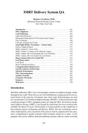
For this test, we expect that <strong>the</strong>re will be no overlap in <strong>the</strong><br />
exposed fields if <strong>the</strong> two gantry positions are directly opposite<br />
each o<strong>the</strong>r as depicted in Fig. 1a. Lines are drawn at <strong>the</strong><br />
edges <strong>of</strong> <strong>the</strong> exposed fields to make sure <strong>the</strong> leaves are indeed<br />
parallel to each o<strong>the</strong>r. Just as for <strong>the</strong> box-in-box, <strong>the</strong><br />
angle <strong>of</strong> each line is calculated as <strong>the</strong> arctangent <strong>of</strong> <strong>the</strong> gradient<br />
<strong>of</strong> <strong>the</strong> line. The pass criterion is such that <strong>the</strong> calculated<br />
angles should not differ by more than 1°. In case <strong>of</strong> overlaps<br />
in <strong>the</strong> exposed fields, one possible conclusion is that <strong>the</strong><br />
gantry positions were not directly opposite and <strong>the</strong> <strong>of</strong>fset<br />
distance in source position d 2 is calculated by measuring <strong>the</strong><br />
overlap distance d 1 using similar triangles equation as displayed<br />
in Fig. 1b. Since <strong>the</strong> SAD is much greater than <strong>the</strong><br />
<strong>of</strong>fset distance d 1 , which can be calculated using <strong>the</strong> equation<br />
in Fig. 1b <strong>with</strong> <strong>the</strong> SAD and <strong>the</strong> source to <strong>the</strong> end <strong>of</strong> MLC<br />
distance d, <strong>the</strong> <strong>of</strong>fset angle in degree can be approximately<br />
calculated using Eq. 1<br />
d 1<br />
SAD 180<br />
.<br />
II.B. MLC interleaf leakage<br />
The interleaf leakage test was performed by programming<br />
all leaves to be closed and using <strong>the</strong> 2.5 cm jaw model, <strong>with</strong><br />
<strong>the</strong> gantry fixed at 0° and a beam on time <strong>of</strong> 300 s. The film<br />
was positioned at SAD <strong>with</strong> 5 cm Solid Water as backscattering<br />
material and 1.5 cm Solid Water as buildup material.<br />
In order to normalize <strong>the</strong> film, an open field was exposed<br />
for 10 s <strong>with</strong> <strong>the</strong> same settings except that all leaves<br />
were left open. The difference in exposure times between <strong>the</strong><br />
full open and full closed exposure was considered when dose<br />
normalization was computed. The reason we need to do an<br />
open and closed field is so that we take into account <strong>the</strong><br />
nonuniform cone-shaped intensity pr<strong>of</strong>ile <strong>of</strong> <strong>the</strong> tomo<strong>the</strong>rapy<br />
radiation field.<br />
1<br />
Medical Physics, Vol. 34, No. 7, July 2007
2951 Sarkar et al.: Tomo<strong>the</strong>rapy MLC quality <strong>assurance</strong> patterns 2951<br />
<strong>with</strong> 5 cm Solid Water as backscattering material and 1.5 cm<br />
Solid Water for buildup material.<br />
For <strong>the</strong> analysis, <strong>the</strong> s<strong>of</strong>tware uses linear regression to fit<br />
a line to <strong>the</strong> wedged pr<strong>of</strong>ile. The product moment correlation<br />
coefficient, r a parameter <strong>of</strong> goodness <strong>of</strong> fit <strong>of</strong> linear regression,<br />
is calculated and if <strong>the</strong> value <strong>of</strong> r 2 lies between 0.99<br />
and 1.00, we consider <strong>the</strong> test to be a “pass.”<br />
II.C.2. IEC-Y gradient<br />
The IEC-Y gradient test is similar to <strong>the</strong> IEC-X gradient<br />
test. However, in <strong>the</strong> IEC-X gradient test, <strong>the</strong> couch was not<br />
moved and <strong>the</strong> film was shot once. Due to <strong>the</strong> current inability<br />
to automatically move <strong>the</strong> couch to multiple discrete positions<br />
and having it stay immobile during irradiation, <strong>the</strong><br />
IEC-Y gradient test did not use automatic couch movement.<br />
Instead, <strong>the</strong> couch was manually moved after each exposure.<br />
The sinogram shape was generated using Eq. 2, however,<br />
M wedge matrix was selected to represent <strong>the</strong> opening time for<br />
each field. In total, five fields were generated and <strong>the</strong> ratio <strong>of</strong><br />
MLC opening time was 10%, 20%, 30%, 40% and 50%,<br />
<strong>with</strong> 100% representing a field <strong>with</strong> leaves open <strong>the</strong> whole<br />
time. Thus, even though <strong>the</strong> beam on time was <strong>the</strong> same for<br />
all <strong>the</strong> shots, <strong>the</strong> MLC opening time was different. The selected<br />
jaw setting was <strong>the</strong> 5.0 cm mode, <strong>with</strong> <strong>the</strong> gantry fixed<br />
at 0° and beam on time for each field was 20 s.<br />
To analyze, <strong>the</strong> s<strong>of</strong>tware determines <strong>the</strong> center <strong>of</strong> each<br />
exposed field and samples 50 points to <strong>the</strong> left and right to<br />
get an average dose value in that region. Linear regression is<br />
used to fit a line through <strong>the</strong> center and average dose value.<br />
If <strong>the</strong> value <strong>of</strong> r 2 for <strong>the</strong> line is between 0.99 and 1.0, <strong>the</strong> test<br />
passes.<br />
FIG. 1. Illustration <strong>of</strong> modified checkerboard <strong>of</strong>fset angle calculation. a<br />
Well aligned beam angle; b Misaligned beam angle <strong>with</strong> resulting overlap.<br />
The analysis consists <strong>of</strong> comparing <strong>the</strong> two normalized<br />
pr<strong>of</strong>iles and our pass/fail criterion is set so that at no position<br />
should <strong>the</strong> leakage be more than 1%.<br />
II.C. Single MLC leaf excise<br />
II.C.1. IEC-X gradient<br />
The IEC-X gradient test is used to verify <strong>the</strong> accuracy and<br />
calibration <strong>of</strong> <strong>the</strong> leaves in mimicking a wedge in <strong>the</strong> IEC-X<br />
direction. Since <strong>the</strong> tomo<strong>the</strong>rapy pr<strong>of</strong>ile in <strong>the</strong> IEC-X direction<br />
is cone shaped, we first had to program <strong>the</strong> leaf opening<br />
times to produce a flat field. Then we fur<strong>the</strong>r modulated <strong>the</strong><br />
leaf opening times to produce a wedged distribution in <strong>the</strong><br />
IEC-X direction. The transformation used is given in Eq. 2<br />
W = M wedge • N norm • P depth ,<br />
2<br />
where P depth is <strong>the</strong> pr<strong>of</strong>ile matrix for certain depth<br />
d=1.5 cm for this study, N norm is a matrix to normalize <strong>the</strong><br />
P depth to a flat field, M wedge is a wedge shape matrix, and W<br />
is <strong>the</strong> final matrix for generating <strong>the</strong> sinogram file. The jaw<br />
was set at <strong>the</strong> 5.0 cm mode, <strong>the</strong> gantry was fixed at 0° and<br />
beam on time was 25 s. EDR2 film was positioned at SAD<br />
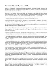
II.D. Complex fields<br />
These tests were designed to verify <strong>the</strong> accuracy and calibration<br />
<strong>of</strong> <strong>the</strong> leaves using a complex field pattern design <strong>of</strong><br />
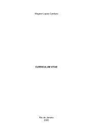
interleaved triangular shapes as shown in Fig. 2 and a more<br />
circular test pattern, <strong>the</strong> “panda,” shown in Fig. 3.<br />
Due to <strong>the</strong> fact that each MLC leaf projects to a size <strong>of</strong><br />
0.625 cm at SAD, ideally we would like to use a 0.6 cm jaw<br />
setting to make each pixel drawn onto <strong>the</strong> film square. O<strong>the</strong>r<br />
jaw settings may be used but <strong>the</strong> pixels will be rectangular<br />
making comparisons between <strong>the</strong> image and <strong>the</strong> film harder.<br />
We do not have any set criteria to fail/pass this test. The<br />
user is expected to visually inspect <strong>the</strong> films and determine if<br />
all <strong>the</strong> straight lines/circles are indeed straight/round and areas<br />
have uniform shading where required.<br />
III. RESULTS<br />
The results <strong>of</strong> <strong>the</strong> custom MLC QA tests as described<br />
above will now be presented in <strong>the</strong> following sections.<br />
III.A.1. Box-in-box<br />
Figure 4a shows <strong>the</strong> film and Fig. 4b shows <strong>the</strong> analysis<br />
output for <strong>the</strong> box-in-box test. An automatic edge detection<br />
algorithm was used to generate <strong>the</strong> latter figure, although<br />
<strong>the</strong> user is also given <strong>the</strong> option <strong>of</strong> drawing lines<br />
Medical Physics, Vol. 34, No. 7, July 2007
2952 Sarkar et al.: Tomo<strong>the</strong>rapy MLC quality <strong>assurance</strong> patterns 2952<br />
FIG. 2. Triangular Complex test pattern.<br />
FIG. 3. Panda Complex test pattern.<br />
across <strong>the</strong> field edges. The angular deviation <strong>of</strong> <strong>the</strong> edges and<br />
mean distance between line pair are reported in Table I.<br />
III.A.2. Modified checkerboard<br />
Figure 5 shows <strong>the</strong> film for <strong>the</strong> modified checkerboard<br />
test and analysis results. Figure 5b is <strong>the</strong> dose map obtained<br />
from Fig. 5a through <strong>the</strong> use <strong>of</strong> a user-defined step-valley<br />
calibration film. The overlap region was identified, and <strong>the</strong><br />
distance was measured to be 1.66 mm, which corresponded<br />
to a gantry <strong>of</strong>fset angle <strong>of</strong> 0.06°. The line-pair angle differences<br />
were 0.04° horizontal pair and 0.34° vertical pair.<br />
III.B. Leakage test<br />
Figure 6a shows <strong>the</strong> film and Fig. 6b shows <strong>the</strong> corresponding<br />
leakage plot given by <strong>the</strong> s<strong>of</strong>tware after conversion<br />
<strong>of</strong> <strong>the</strong> optical density values to dose using <strong>the</strong> step-valley<br />
calibration film. The averaged interleaf leakage was<br />
0.53% ±0.09%.<br />
III.C.2. IEC-Y gradient<br />
IEC-Y gradient film and dose pr<strong>of</strong>ile plot are shown in<br />
Figs. 8a and 8b, respectively. The value <strong>of</strong> r 2 for <strong>the</strong> line<br />
fitted by linear regression is 1.0, making this test pass according<br />
to our set criterion.<br />
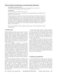
III.D. Complex fields<br />
Figures 9a and 9b show <strong>the</strong> films for complex field<br />
tests. A visual qualitative evaluation shows that <strong>the</strong>re are no<br />
discrepancies seen in <strong>the</strong> film compared to <strong>the</strong> predicted pattern<br />
in Fig. 2.<br />
For <strong>the</strong> sake <strong>of</strong> completeness, we summarized our results<br />
and our set pass/fail criterion for each test in Table II.<br />
III.C.1. IEC-X gradient<br />
Figure 7a shows <strong>the</strong> film and Fig. 7b <strong>the</strong> pr<strong>of</strong>ile plot<br />
after conversion to dose. The value for <strong>the</strong> square <strong>of</strong> <strong>the</strong><br />
product moment correlation coefficient, r 2 , for <strong>the</strong> fitted line<br />
is 1.0, which makes this test pass according to our criterion.<br />
TABLE I. Parameters determined for <strong>the</strong> box-in-box test.<br />
Line pair Angle difference degree Average distance mm<br />
Top two lines 0.27 5.36<br />
Bottom two lines 0.18 5.25<br />
Left two lines 0.47 14.59<br />
Right two lines 0.00 12.22<br />
FIG. 4. a Box in box film; b auto edge detection technique was used and<br />
edges overlaid lines were drawn by <strong>the</strong> user.<br />
Medical Physics, Vol. 34, No. 7, July 2007
2953 Sarkar et al.: Tomo<strong>the</strong>rapy MLC quality <strong>assurance</strong> patterns 2953<br />
FIG. 5. a Modified checkerboard film; b analysis result for dose map.<br />
IV. DISCUSSIONS<br />
Different QA procedures about tomo<strong>the</strong>rapy MLC have<br />
been proposed by Balog et al. or Fenwick et al. 10–12 However,<br />
<strong>the</strong> previous studies <strong>of</strong> QA procedures about tomo<strong>the</strong>rapy<br />
MLC focused on <strong>the</strong> MLC design and MLC alignment<br />
<strong>with</strong> o<strong>the</strong>r components and did not concentrate solely<br />
on <strong>the</strong> MLC itself. In this study, <strong>the</strong> procedures are designed<br />
to test <strong>the</strong> tomo<strong>the</strong>rapy MLC alone, and it can be routinely<br />
used for clinical test. The methodology proposed can be also<br />
used for o<strong>the</strong>r type binary MLCs, such as <strong>the</strong> Peacock system’s<br />
MIMiC ® <strong>collimator</strong> since our center possesses both<br />
systems. It should also be noted that we have designed both<br />
<strong>the</strong> procedures and analysis tool, which will greatly help in<br />
implementing <strong>the</strong> QA process.<br />
Tasks A and B were directly derived from previously published<br />
testing procedures. In task A, previous studies about<br />
MLC alignment <strong>with</strong> <strong>the</strong> beam and MLC twist used different<br />
procedures. Here we proposed <strong>the</strong> “box-in-box” and “modified<br />
checkerboard” since <strong>the</strong>y are accepted as routine test for<br />
<strong>the</strong> Peacock system’s MIMiC ® <strong>collimator</strong> but can be adapted<br />
to any binary <strong>collimator</strong>. Also, <strong>the</strong>se two tests are easily understood<br />
and analyzed. Task B is also overlapped <strong>with</strong><br />
T&G-PB test by Balog et al. 10 Again, <strong>the</strong> procedure we propose<br />
focuses on <strong>the</strong> MLC itself instead <strong>of</strong> considering it as<br />
part <strong>of</strong> a whole system. Task C focuses on single leaf motion.<br />
To generate <strong>the</strong> gradient shape, leaf timing and movement<br />
accuracy can be examined. Task D is a more general test that<br />
can be used to quickly verify whe<strong>the</strong>r <strong>the</strong> whole MLC is<br />
working well or not.<br />
In order to implement <strong>the</strong> QA procedures, we recommend<br />
that tasks A and B are used whenever <strong>the</strong> MLC has been<br />
replaced as part <strong>of</strong> <strong>the</strong> acceptance test. Task C can be used<br />
whenever a single MLC leaf is suspected to be problematic.<br />
Task D can be used as part <strong>of</strong> monthly QA procedure since it<br />
can test <strong>the</strong> MLC’s function as a whole. All <strong>of</strong> those procedures<br />
can be used as part <strong>of</strong> annual QA about <strong>the</strong> tomo<strong>the</strong>rapy<br />
MLC. For tasks A, C, and D, two procedures are<br />
proposed and <strong>the</strong> reader can pick one or both for a routine<br />
test. The setup and delivery time for each procedure is<br />
around 10 min. Since we have <strong>the</strong> s<strong>of</strong>tware tool developed<br />
for result analysis, this part should take no more than 5 min.<br />
In general, most <strong>of</strong> <strong>the</strong> tests we performed gave <strong>the</strong> expected<br />
results and all passed <strong>with</strong>in <strong>the</strong> set criteria. However,<br />
<strong>the</strong>re are some interesting findings in <strong>the</strong> results that we discuss<br />
in this section.<br />
For <strong>the</strong> box in box, <strong>the</strong> angle discrepancy between <strong>the</strong><br />
sides <strong>of</strong> <strong>the</strong> two fields was very small, which means that<br />
<strong>the</strong>re is no twist in <strong>the</strong> MLC along <strong>the</strong> IEC-Y /Z plane. It<br />
should be noted that <strong>the</strong> shorter side in plane <strong>of</strong> <strong>the</strong> boxin-box<br />
pattern verifies MLC alignment while <strong>the</strong> longer side<br />
transverse distance verifies <strong>the</strong> jaw alignment. This is because<br />
<strong>the</strong> jaws are used to define <strong>the</strong> field size along <strong>the</strong> IEC-<br />
Y direction such that <strong>the</strong>ir edges define <strong>the</strong> borders along <strong>the</strong><br />
IEC-X direction. The fact that <strong>the</strong> distances on opposite sides<br />
agreed as well implied that <strong>the</strong>re is not much <strong>of</strong> a discrepancy<br />
in gantry positioning. Since <strong>the</strong> distances did not agree<br />
<strong>with</strong> each o<strong>the</strong>r <strong>with</strong>in submillimeter range, it meant that <strong>the</strong><br />
source at <strong>the</strong> second angle was not directly opposite <strong>the</strong> location<br />
in <strong>the</strong> first position. This finding was also proven by<br />
<strong>the</strong> modified checkerboard test where field overlap was<br />
found. The film for this test clearly showed some overlap in<br />
<strong>the</strong> exposed field. Even though <strong>the</strong> overlap distance was<br />
small 1.66 mm, it still showed that <strong>the</strong>re was an amount <strong>of</strong><br />
angle discrepancy 0.06°. The discrepancy may be due to<br />
TABLE II. Summary <strong>of</strong> results and pass/fail criteria set for each test.<br />
Test name Measured parameter Set pass/fail criterion Measured value<br />
Box in box Angle between corresponding edges 0.5° a 0–0.47°<br />
Modified checkerboard Gantry <strong>of</strong>fset angle 1° 0.06°<br />
Angle between corresponding edges 0.5° a 0.04–0.34°<br />
Leakage test Percentage leakage across field 1% 0.53% ±0.09%<br />
IEC-X wedge<br />
Square <strong>of</strong> <strong>the</strong> product moment correlation coefficient<br />
0.99–1.00 1.00<br />
<strong>of</strong> fitted line, r 2<br />
IEC-Y wedge<br />
Square <strong>of</strong> <strong>the</strong> product moment correlation coefficient<br />
0.99–1.00 1.00<br />
<strong>of</strong> fitted line, r 2<br />
Linear complex pattern Lines in pattern should not have any breaks None set No discrepancies observed<br />
Panda complex pattern Circles in pattern should be as expected None set No discrepancies observed<br />
a This follows <strong>the</strong> pass/fail criterion set by TomoTherapy, Inc. in <strong>the</strong>ir version <strong>of</strong> <strong>the</strong> MLC axis/gantry-rotation alignment tests.<br />
Medical Physics, Vol. 34, No. 7, July 2007
2954 Sarkar et al.: Tomo<strong>the</strong>rapy MLC quality <strong>assurance</strong> patterns 2954<br />
FIG. 7. a X-wedge film; b pr<strong>of</strong>ile plot after converting into dose map.<br />
FIG. 6. a Leakage film; b leakage pr<strong>of</strong>ile.<br />
ei<strong>the</strong>r gantry positioning error or a small source position <strong>of</strong>fset<br />
from <strong>the</strong> planned source position that is hard to control.<br />
The reason for such a small angle discrepancy giving an<br />
observable overlap is that <strong>the</strong>re is a zoom factor about 2.4<br />
due to <strong>the</strong> relative distances between <strong>the</strong> source, MLC and<br />
film.<br />
The interleaf leakage check result 0.53% ±0.09% was<br />
very close to what we expected and agreed <strong>with</strong> previously<br />
reported data <strong>of</strong> 0.43%. 11 Tomo<strong>the</strong>rapy MLC has less leakage<br />
than o<strong>the</strong>r MLC such as <strong>the</strong> 1.9% to 2.0% leakage <strong>of</strong> <strong>the</strong><br />
Siemens MLC reported by Bayouth, Wendt, and Morrill. 3<br />
The IEC-X gradient shot showed that <strong>the</strong> leaf open times<br />
can be very well regulated to give <strong>the</strong> steady graduation <strong>of</strong><br />
doses from one side to <strong>the</strong> o<strong>the</strong>r. Since <strong>the</strong> creation <strong>of</strong> <strong>the</strong><br />
sinogram required for this exposure only involved applying a<br />
wedge shape to a flat field leaf pattern, we showed that one<br />
can successfully use modulated opening times to create a flat<br />
field from <strong>the</strong> cone-shaped field typical <strong>of</strong> <strong>the</strong> <strong>helical</strong> tomo<strong>the</strong>rapy<br />
unit. On <strong>the</strong> IEC-Y gradient test, <strong>the</strong> dose pr<strong>of</strong>iles are<br />
fairly flat inside each discrete step. However, <strong>the</strong>re are some<br />
penumbra effects on <strong>the</strong> edge <strong>of</strong> <strong>the</strong> step wedge as shown in<br />
Fig. 8b. It should also be noted that we only put a few<br />
discrete levels for <strong>the</strong> IEC-Y test mostly because each level<br />
required a different procedure, making <strong>the</strong> acquisition <strong>of</strong> <strong>the</strong><br />
film a long process. This test can be made much more “user<br />
friendly” if and when Tomo<strong>the</strong>rapy Inc. makes <strong>the</strong> TABLE<br />
_DISCRETE 14 option available to users. This option allows<br />
<strong>the</strong> table to move to a discrete position and wait for some<br />
dose to be delivered before moving to a new position. This<br />
would <strong>the</strong>n allow us to complete <strong>the</strong> whole process <strong>with</strong>out<br />
having to load multiple procedures and would represent a<br />
useful test <strong>of</strong> couch positioning verification.<br />
We should also point out here that <strong>the</strong>se two tests are not<br />
meant to measure <strong>the</strong> dosimetric capabilities <strong>of</strong> <strong>the</strong> linear<br />
accelerator. They are ra<strong>the</strong>r intended to assess <strong>the</strong> capabilities<br />
<strong>of</strong> <strong>the</strong> MLC leaves to move in such a way as to provide<br />
a wedged distribution. It is <strong>the</strong> authors’ belief that both <strong>of</strong><br />
<strong>the</strong>se tests are useful in monitoring reproducibility <strong>of</strong> leaf<br />
motion over time assuming <strong>the</strong> dose pr<strong>of</strong>ile from <strong>the</strong> linear<br />
accelerator has not changed. The first time this test is done,<br />
<strong>the</strong> results can be defined to be standards against which fur<strong>the</strong>r<br />
tests are compared.<br />
The complex field tests can be customized based on different<br />
bitmap files input by <strong>the</strong> users. In one test, a set <strong>of</strong><br />
triangular shapes provided an easy way to promptly identify<br />
errors in MLC leaf movement. Positional discrepancies can<br />
be easily detected and <strong>the</strong> leaf responsible for <strong>the</strong> error can<br />
be easily identified. The sinogram for <strong>the</strong> “Panda” test was<br />
created from binary bitmap file, and it only shows black and<br />
white on <strong>the</strong> film as shown in Fig. 9b. While <strong>the</strong>se tests<br />
may seem ra<strong>the</strong>r simple at first glance, it is <strong>the</strong> authors’ belief<br />
that users <strong>of</strong> this technique should be able to immediately<br />
point out where a problem exists, including a MLC leaf motor<br />
that has gone out <strong>of</strong> order. Due to <strong>the</strong> regularity <strong>of</strong> <strong>the</strong><br />
pattern, it should immediately be obvious which leaf did not<br />
behave as expected and point <strong>the</strong> service engineers in <strong>the</strong><br />
Medical Physics, Vol. 34, No. 7, July 2007
2955 Sarkar et al.: Tomo<strong>the</strong>rapy MLC quality <strong>assurance</strong> patterns 2955<br />
FIG. 9. Complex field A films: a Triangular pattern; b “Panda” pattern.<br />
FIG. 8. a IEC-Y gradient film; b pr<strong>of</strong>ile plot from Fig. 8a after converting<br />
to dose map. The thin line represents <strong>the</strong> total pr<strong>of</strong>ile and <strong>the</strong> points<br />
denoted by stars represent sampled points. Linear regression was determined<br />
by <strong>the</strong> center location <strong>of</strong> each bar and <strong>the</strong> averaged dose value for <strong>the</strong><br />
sampled points.<br />
right direction for repairs. This would be an especially useful<br />
tool should <strong>the</strong>re be regular problems <strong>with</strong> dose validation<br />
plans and a problem is suspected <strong>with</strong> <strong>the</strong> MLCs. These tests<br />
could also be run during commissioning <strong>of</strong> <strong>the</strong> equipment<br />
and <strong>the</strong> films used as standards to evaluate any changes in<br />
machine performance <strong>with</strong> time.<br />
In summary, <strong>the</strong> seven patterns we designed can be used<br />
to test several MLC properties <strong>of</strong> <strong>the</strong> <strong>helical</strong> tomo<strong>the</strong>rapy<br />
unit such as MLC alignment, MLC interleaf leakage,<br />
beam-on timing, leaf location, etc. The patterns are useful for<br />
clinical quality <strong>assurance</strong> <strong>of</strong> <strong>the</strong> MLC for a <strong>helical</strong> tomo<strong>the</strong>rapy<br />
unit.<br />
V. CONCLUSIONS<br />
In this study, seven test patterns were designed as part <strong>of</strong><br />
a QA toolkit for <strong>the</strong> MLC <strong>of</strong> a <strong>helical</strong> tomo<strong>the</strong>rapy unit. A<br />
s<strong>of</strong>tware platform called “TOMO MLC QA” was developed to<br />
facilitate <strong>the</strong> analysis <strong>of</strong> <strong>the</strong> seven tomo<strong>the</strong>rapy MLC QA<br />
tests. The s<strong>of</strong>tware can be easily adapted to any treatment<br />
Medical Physics, Vol. 34, No. 7, July 2007
2956 Sarkar et al.: Tomo<strong>the</strong>rapy MLC quality <strong>assurance</strong> patterns 2956<br />
center <strong>with</strong> a <strong>helical</strong> tomo<strong>the</strong>rapy unit to perform customized<br />
tomo<strong>the</strong>rapy MLC QA or to standardize testing. Fur<strong>the</strong>r test<br />
patterns can be developed based on <strong>the</strong> “TOMO MLC QA” platform.<br />
The seven designed test patterns for tomo<strong>the</strong>rapy MLC<br />
QA are not aimed to test all characteristics <strong>of</strong> <strong>the</strong> tomo<strong>the</strong>rapy<br />
MLC. However, <strong>the</strong> patterns allow <strong>the</strong> users to test<br />
some <strong>of</strong> <strong>the</strong> mechanical and dosimetric properties <strong>of</strong> <strong>the</strong>ir<br />
tomo<strong>the</strong>rapy MLC. The analysis results based on <strong>the</strong> seven<br />
test patterns from our institution were reported. All tests<br />
passed at <strong>the</strong> in-house set criteria. This means <strong>the</strong> tomo<strong>the</strong>rapy<br />
MLC is well designed and aligned. However, several<br />
minute problems regarding beam angle position were also<br />
found and <strong>the</strong> effects on <strong>the</strong> dose require fur<strong>the</strong>r investigation.<br />
ACKNOWLEDGMENT<br />
This work was performed under <strong>the</strong> following grant: Cancer<br />
Center Council No. 10-000-022-459-08-849.<br />
a Electronic mail: cshi@ctrc.net<br />
1 A. Boyer, P. Biggs, J. Galvin, E. Klein, T. LoSasso, D. Low, K. Mah, and<br />
C. Yu, “Basic applications <strong>of</strong> <strong>multileaf</strong> <strong>collimator</strong>s: Report <strong>of</strong> task group<br />
No. 50 radiation <strong>the</strong>rapy committee,” American Institute <strong>of</strong> Physics for<br />
<strong>the</strong> AAPM, New York, NY 2001.<br />
2 G. A. Ezzell, J. M. Galvin, D. Low, J. R. Palta, I. Rosen, M. B. Sharpe, P.<br />
Xia, Y. Xiao, L. Xing, and C. X. Yu, “Guidance document on delivery,<br />
treatment planning, and clinical implementation <strong>of</strong> IMRT: Report <strong>of</strong> <strong>the</strong><br />
IMRT subcommittee <strong>of</strong> <strong>the</strong> AAPM radiation <strong>the</strong>rapy committee,” Med.<br />
Phys. 308, 2089–2115 2003.<br />
3 J. E. Bayouth, D. Wendt, and S. M. Morrill, “MLC quality <strong>assurance</strong><br />
techniques for IMRT applications,” Med. Phys. 305, 743–750 2003.<br />
4 J. E. Bayouth and S. M. Morrill, “MLC dosimetric characteristics for<br />
small field and IMRT applications,” Med. Phys. 309, 2545–2552<br />
2003.<br />
5 T. J. LoSasso, “IMRT delivery system QA,” www.medicalphysics.org/<br />
apps/medicalphysicsedit/LoSasso.pdf 2003.<br />
6 J. C. L. Chow and G. N. Grigorov, “Measurement for <strong>the</strong> MLC leaf<br />
velocity pr<strong>of</strong>ile by considering <strong>the</strong> leaf leakage using a radiographic<br />
film,” Phys. Med. Biol. 51, N299–306 2006.<br />
7 K. M. Dinesh, N. Thirumavalavan, K. D. Venugopal, and M. Babaiah,<br />
“QA <strong>of</strong> intensity-modulated beams using dynamic MLC log files,” Med.<br />
Phys. 311, 36–41 2006.<br />
8 M. N. Graves, A. V. Thompson, M. K. Martel, L. M. Daniel, and A. F.<br />
Benedick, “Calibration and quality <strong>assurance</strong> for rounded leaf-end MLC<br />
systems,” Med. Phys. 2811, 2227–2233 2001.<br />
9 Y. Yang and L. Xing, “Using <strong>the</strong> volumetric effect <strong>of</strong> a finite-sized detector<br />
for routine quality <strong>assurance</strong> <strong>of</strong> <strong>multileaf</strong> <strong>collimator</strong> leaf positioning,”<br />
Med. Phys. 303, 433–441 2003.<br />
10 J. Balog, T. R. Mackie, D. Pearson, S. Hui, B. Paliwal, and R. Jeraj,<br />
“Benchmarking beam alignment for a clinical <strong>helical</strong> tomo<strong>the</strong>rapy device,”<br />
Med. Phys. 306, 1118–1127 2003.<br />
11 J. P. Balog, D. Lucas, C. DeSouza, and R. Crilly, “Helical tomo<strong>the</strong>rapy<br />
radiation leakage and shielding considerations,” Med. Phys. 323, 710–<br />
719 2005.<br />
12 J. D. Fenwick, W. A. Tome, H. A. Jaradat, S. K. Hui, J. A. James, J. P.<br />
Balog, C. N. DeSouza, D. B. Lucas, G. H. Olivera, T. R. Mackie, and B.<br />
R. Paliwal, “<strong>Quality</strong> <strong>assurance</strong> <strong>of</strong> a <strong>helical</strong> tomo<strong>the</strong>rapy machine,” Phys.<br />
Med. Biol. 49, 2933–2953 2004.<br />
13 Varian Inc., “DMLC QA test patterns and procedures,” Varian medical<br />
systems, P/N 10012878-01 2001.<br />
14 C. Y. Shi, N. Papanikolaou, Y. Yan, X. J. Weng, and H. Jiang, “Analysis<br />
<strong>of</strong> <strong>the</strong> sources <strong>of</strong> uncertainty for EDR2 film-based IMRT quality <strong>assurance</strong>,”<br />
J. Appl. Clin. Med. Phys. 72, 2006.<br />
15 TomoTherapy Inc., “Hi·Art system physics guide,” TomoTherapy Inc.,<br />
T-USR-HB0013E-0804 2004.<br />
Medical Physics, Vol. 34, No. 7, July 2007