Fluorescence Lifetime Microsystem - Instech Laboratories, Inc.
Fluorescence Lifetime Microsystem - Instech Laboratories, Inc.
Fluorescence Lifetime Microsystem - Instech Laboratories, Inc.

You also want an ePaper? Increase the reach of your titles
YUMPU automatically turns print PDFs into web optimized ePapers that Google loves.
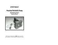
Operating Manual<br />
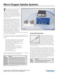
<strong>Fluorescence</strong> <strong>Lifetime</strong> Micro Oxygen Monitoring System<br />
Manual version 3.1<br />
June 25, 2010<br />
<strong>Instech</strong> <strong>Laboratories</strong>, <strong>Inc</strong>.<br />
5209 Militia Hill Road<br />
Plymouth Meeting, PA 19462 USA<br />
Tel 800-443-4227<br />
www.instechlabs.com
Set Up Hardware and Install Software<br />
1. Unpack all parts.<br />
2. If you have ordered more than one channel, you will receive a 10 port USB hub to connect all<br />
NeoFoxes to your PC. More channels can be added without changing the hub. The small end of<br />
the USB should be connected to the rear of the hub. The other end to an unused USB input on<br />
your PC. It will not be necessary to attach the hub power supply for only 2 channels. The<br />
computer should recognize the hub and automatically install it.<br />
3. For single channel units, no hub is required and the USB cable should be connected directly<br />
from the NeoFox to the PC.<br />
4. Open the Ocean Optics CD.<br />
5. The NeoFox Manual.pdf is rather lengthy and printing of the entire manual is not necessary.<br />
Keep the file on your desktop for reference.<br />
6. Install the software by running the appropriate .msi file. Make sure not to run the Viewer before<br />
the USB drivers have been installed.<br />
7. Attach each Neo to the hub with cables provided and power on the Neos.<br />
8. New hardware message should come up and accept the Neos.<br />
9. Once the units have been recognized as USB ports, it is best to Check the Device Manager in<br />
My Computer—Properties-Hardware for the presence of Ocean Optics Neofox in the USB list.<br />
Once verified, then it is OK to start the viewer.<br />
10. When the Viewer is started, tabs corresponding to the serial number of the Neos should be<br />
seen above the display as it cycles through and detects them.<br />
11. You switch between them by clicking the top tabs (active one is the lighter color).<br />
12. <strong>Instech</strong> will have installed the latest NeoFoxImage bin file-Now at v2.05.<br />
Set NeoFox Parameters<br />
The <strong>Instech</strong> chambers can come with two different fluorescent patch materials.<br />
FOXY patches are best for general purpose applications where exposure to alcohol can be avoided.<br />
Alcohol cannot be used in the chamber without seriously degrading the FOXY patch coating. Signals<br />
from this material will be high with lowest noise.<br />
HIOXY patch versions will be resistant to organic solvents but will result in lower signal levels and<br />
slightly higher noise levels. This material is recommended for mitochondrial studies where it is<br />
necessary to rinse out inhibitors with alcohol. If water soluble inhibitors are used then the FOXY<br />
material is preferable. Since the gains have to be set high for this material, it makes it more susceptible<br />
2
to room light interference and will add to the noise. Covering the top of the glass plug will reduce this<br />
effect.<br />
Parameter Setup for each channel is required prior to calibration and to set the system for the patch in<br />
the chamber and will be different depending upon the patch material. Changing these parameters after<br />
calibration may affect the readings.<br />
FOXY SETUP<br />
1. In the View pull down select Advanced Settings.<br />
2. Select FOXY for the sensor<br />
3. Select Manual Gain.<br />
4. Use the checkout sheet provided and set the values to match the sheet for initial operation.<br />
5. Check Blue amplitude signal level by displaying Advanced Status. It should be in 10,000 range.<br />
The small arrow on the Signal level bar graph should be in the green area.<br />
Typical FOXY Setup<br />
HIOXY Setup<br />
1. In the View pull down select Advanced Settings.<br />
2. Select HIOXY for the sensor<br />
3. Select Manual Gain.<br />
4. Change LED rate down to 23.44 by hitting the – button.<br />
5. Alter Blue gain and LED and possibly the APD voltage, until blue sensor signal looks like that<br />
shown below in the sensor waveform panel.<br />
3
6. Check Blue amplitude signal level by displaying Advanced Status. It should be in 3000 or<br />
greater. The small arrow on the Signal level bar graph should be in the green area.<br />
Typical HIOXY Setup<br />
The Auto mode in Gain setting does not always select the optimum values and once set in Manual<br />
mode it can be left in that condition.<br />
Scans to Average should be set around 100, each scan is 10 msec. or a 1 second averaging time. This<br />
will reduce noise without degrading data dynamics of data acquisition since the patch response time is<br />
longer than 1 sec.<br />
Temperature Probe<br />
If you have a temperature probe, insert it into the block and attach the cable to the rear of the NeoFox<br />
mini-phono input.<br />
It is not necessary to have more than 1 probe, even for multiple chambers as long as they are in series<br />
from a single circulating water bath.<br />
In the Calibration screen there is a place to use the probe as the temperature input. Select that for the<br />
Neo that has it attached.<br />
Once that temperature is known, select “Use fixed temperature” on the others and manually enter the<br />
operating temperature.<br />
By doing this, the “micromoles/liter” display will be compensated for temperature, no other units will be<br />
effected.<br />
4
Calibrating Probes<br />
Meaningful Oxygen values will be displayed only after a Two Point Calibration has been performed for<br />
each channel.<br />
Calibrations should always be performed at your final operating temperature which is the reason the<br />
circulating water bath connections. Oxygen values are temperature sensitive. Start with the chamber<br />
that has the temperature probe installed. Record that temperature and insert the value into the<br />
temperature field for all other chambers in their respective calibration screens and select No temp<br />
probe installed. This will result in the proper conversion to micromoles/liter.<br />
1. Remove the plug and place air equilibrated buffer into the chamber, making sure it is at<br />
temperature. Take care with this step. Place buffer in a vial in the water bath with an air space<br />
above the fluid and shake frequently.<br />
Remember you will start in % Oxygen units. The percent oxygen is not directly 20.9%.<br />
This is only true when measuring gaseous oxygen. The partial pressure in mmHg is<br />
.209*(760mmHg-Vapor pressure of water at your operating temperature* see table in<br />
Appendix 1). Percent will be this value divided by 760. For example, at 37C partial<br />
pressure should be 148.9 mmHg and 19.6%. Use this value as your ambient sample<br />
calibration value.<br />
5
2. Click the button to enter the current tau reading in point #2.<br />
3. Add sodium dithionite crystals into the chamber, while stirring, until the tau stops increasing.<br />
Titrate for maximum tau. Remember this amount. Excess is permissible. Use that value for point<br />
#1. Remember to click in the graph area before downloading the calibration values to each Neo<br />
unit. Two blue dots will update. Calibrations are stored there, not in your computer, and will be<br />
recalled for the next use. If you do not click the graph first, the calibration will not update.<br />
4. Rinse well and repeat for other chambers.<br />
5. It is good practice to record the tau values for future comparisons.<br />
6. At this time, oxygen values in excess of 100 will not be displayed in the oxygen window but will<br />
be correctly logged and graphed.<br />
7. Temperature probes are for information and do not compensate any of the readings except for<br />
micromoles/liter. Again, only one sensor is needed for the string of chambers.<br />
6
Operating the Chamber<br />
1. Remove the plug/collar assembly by lifting straight up.<br />
2. Add liquid to the chamber-slightly in excess of stated volume.<br />
3. Orient the plug and collar assembly so that the high side of the bevel aligns with the angled fill<br />
port hole (leftmost illustration). Set screw should indicate the high side.<br />
4. Slowly lower the plug while checking for bubbles and allow the excess to spill out into the cup<br />
5. Seal the chamber by rotating the plug assembly 180 degrees (rightmost illustration).<br />
6. To minimize air leakage, leave the small column of fluid in the angled fill port.<br />
7. Additions may be made by rotating the plug to the fill position (center). Use a needle or narrow<br />
tipped pipette that allows excess fluid to pass by and spill into the cup ring. The long needle or<br />
tip is preferred to make the additions at the bottom of the chamber and the overflow is at the<br />
top.<br />
8. Check that no air has been injected. Eppendorf pipettes will finish with an air bubble and are not<br />
recommended to be used in their normal mode.<br />
The chamber volume is approximate and should be checked by the user.<br />
Please try to minimize spills to prevent damage to the stirring motors.<br />
Maintenance<br />
No maintenance is required for the long life sensing patch as it is part of the chamber. If damaged, the<br />
cup will need to be returned for repair.<br />
Cup Removal or Replacement<br />
1. Remove the glass plug.<br />
2. Remove the SMA fiber connection from the block coupler.<br />
3. Loosen the setscrew across from the fiber attachment.<br />
4. Lift the cup vertically out and remove the stir bar.<br />
5. Smear the underside of the new cup with silicone grease to prevent spilled liquid from running<br />
under the cup lip and entering the stirring motor cavity.<br />
7
6. Drop the cup into the block and twist to visually align the sensor hole with the coupling sleeve.<br />
This will distribute the silicone grease as well.<br />
7. Replace the SMA coupler into the sleeve.<br />
8. When properly aligned, the tip of the SMA connector will engage the recess in the titanium<br />
cup. Gently rotate the cup back and forth until rotation is stopped by this engagement. This<br />
assures final alignment is correct. Use the blue tubular wrench in this process.<br />
9. Run the software for this channel to assure signal is maximized. When properly positioned<br />
retighten the cup hold set screw (front top of block).<br />
10. Once parameters have been set for this patch material, switch view to show Advanced Setup<br />
and scroll down to Blue Intensity. It should be 3000 or greater. Much greater is OK If it is low,<br />
either the alignment is incorrect or parameters need to be adjusted.<br />
11. Replace stir bar and glass plug.<br />
Replacing Glass Plug/Valve<br />
Chips may make it difficult to clear air bubbles.<br />
1. Remove the plug.<br />
2. Loosen the setscrew and remove the glass.<br />
3. The correct position of the plug within the black collar is when the glass is flush with the top<br />
edge of the collar.<br />
4. Align the setscrew with the highest point of the bevel to permit clearance of air bubbles.<br />
5. Retighten set screw.<br />
Installing Firmware Updates<br />
1. Make to new Image file available e. g. on the desktop.<br />
2. Stop data collection.<br />
3. Select Options, then Firmware Update and follow prompts<br />
4. Do not disconnect power during the update.<br />
5. Repeat for each unit to be updated.<br />
8
Appendix 1<br />
Courtesy of hyperphysics.phy-astr.gsu.edu/HBASE/kinetic/watvap.html<br />
9