DEC Module 50/5 Operating Instructions (englisch ... - Maxon Motor ag
DEC Module 50/5 Operating Instructions (englisch ... - Maxon Motor ag
DEC Module 50/5 Operating Instructions (englisch ... - Maxon Motor ag

You also want an ePaper? Increase the reach of your titles
YUMPU automatically turns print PDFs into web optimized ePapers that Google loves.
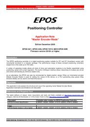
maxon motor<br />
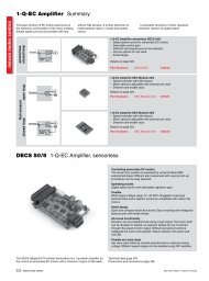
<strong>Operating</strong> <strong>Instructions</strong> 1-Q-EC Amplifier <strong>DEC</strong> <strong>Module</strong> <strong>50</strong>/5<br />
10.3 Design rules<br />
To help customers designing an application specific motherboard and for<br />
correct and save function of the <strong>DEC</strong> <strong>Module</strong> <strong>50</strong>/5 these rules should be<br />
followed.<br />
10.3.1 Ground<br />
10.3.2 Layout<br />
a<br />
The ground (Gnd) pins of the <strong>DEC</strong> <strong>Module</strong> are internally connected (same<br />
electrical potential). It is common practice to place a ground plane on the motherboard<br />
and it is necessary to connect pins [9], [10], [14], [16] and [24] with<br />
thick tracks to the power supply volt<strong>ag</strong>e ground<br />
Pin Signals Description<br />
9 Gnd Ground<br />
10 Gnd Ground<br />
14 Gnd Ground<br />
16 Gnd Ground<br />
24 Gnd Ground<br />
If ground safety earth is mandatory, connect the ground plane over several<br />
parallel capacitors to the ground safety earth. Ceramic chip capacitors with<br />
47 nF and 100 V are suggested.<br />
Motherboard layouts for <strong>DEC</strong> <strong>Module</strong> <strong>50</strong>/5 should follow these rules:<br />
––<br />
Pins [7] and [8] +V CC<br />
: Use thick track to connect to the fuse.<br />
––<br />
Pins [9], [10], [14], [16] and [24]: Use thick tracks to connect to supply<br />
volt<strong>ag</strong>e‘s ground (Gnd).<br />
––<br />
The width and copper plating thickness of the power supply volt<strong>ag</strong>e and<br />
motor winding traces depend on the maximum current expected in the<br />
application. A minimum of 75 mil width at 70 μm thickness is recommended.<br />
10.4 THT footprint<br />
Top view<br />
Dimensions in [mm]<br />
10.5 Pin description<br />
10.6 Technical data<br />
10.7 Dimensional drawing<br />
See chapter «3 Pin assignment <strong>DEC</strong> <strong>Module</strong> <strong>50</strong>/5»<br />
See chapter «2 Technical data»<br />
See chapter «8 Dimensional drawing»<br />
May 2013 Edition / document number 1094861PDFE 1094861PDFE _PDF_E - 04 / subject to change<br />
maxon motor control 17