Manual Chapter 2 - Installation - Fluid Components International
Manual Chapter 2 - Installation - Fluid Components International
Manual Chapter 2 - Installation - Fluid Components International

Create successful ePaper yourself
Turn your PDF publications into a flip-book with our unique Google optimized e-Paper software.
CHAPTER 2 - INSTALLATION<br />
2. <strong>Installation</strong><br />
FLUID COMPONENTS, INTL<br />
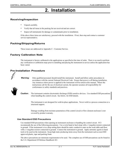
Receiving/Inspection<br />
• Unpack carefully.<br />
• Verify that all items in the packing list are received and are correct.<br />
• Inspect all instruments for damage or contaminants prior to installation.<br />
If the above three items are satisfactory, proceed with the installation. If not, then stop and contact a customer<br />
service representative.<br />
Packing/Shipping/Returns<br />
These issues are addressed in Appendix C - Customer Service.<br />
Factory Calibration Note<br />
The instrument is factory calibrated to the applications as specified at the time of order. There is no need to perform<br />
any verification or calibration steps prior to installing and placing the instrument in service unless the application has<br />
been varied.<br />
Pre-<strong>Installation</strong> Procedure<br />
Warning:<br />
Only qualified personnel should install this instrument. Install and follow safety procedures in<br />
accordance with the current National Electrical Code. Ensure that power is off during installation.<br />
Any instances where power is applied to the instrument will be noted in this manual. Where the<br />
instructions call for the use of electrical current, the operator assumes all responsibility for<br />
conformance to safety standards and practices.<br />
Caution:<br />
The instrument contains electrostatic discharge (ESD) sensitive devices. Use standard ESD precautions<br />
when handling the control circuit. See below, for ESD details.<br />
The instrument is not designed for weld-in-place applications. Never weld to a process connection or a<br />
structural support.<br />
Damage resulting from moisture penetration of the control circuit or flow element enclosure is not<br />
covered by product warranty.<br />
Use Standard ESD Precautions<br />
Use standard ESD precautions when opening an instrument enclosure or handling the control circuit. FCI<br />
recommends the use of the following precautions: Use a wrist band or heel strap with a 1 megohm resistor connected<br />
to ground. If the instrument is in a shop setting there should be static conductive mats on the work table and floor<br />
with a 1 megohm resistor connected to ground. Connect the instrument to ground. Apply antistatic agents to hand<br />
tools to be used on the instrument. Keep high static producing items away from the instrument such as non-ESD<br />
approved plastic, tape and packing foam.<br />
The above precautions are minimum requirements to be used. The complete use of ESD precautions can be found in<br />
the U.S. Department Of Defense Handbook 263.<br />
Doc. No. 06EN003246 Rev. B 2 - 1 FLTÔ Series FlexSwitchÔ
FLUID COMPONENTS, INTL<br />
CHAPTER 2 - INSTALLATION<br />
Prepare or Verify Sensing Element Location<br />
Prepare the process pipe for installation, or inspect the already prepared location to ensure that the instrument will fit<br />
into the system.<br />
Review the requirement for the supply power and alarm circuit connections.<br />
Verify Dimensions<br />
Verify the instrument's dimensions versus the process location to be sure of a correct fit. Also see Appendix A for<br />
dimensions.<br />
Verify Sensing Element Flow Direction and Placement Orientation (Flow Application)<br />
For flow detection, the sensing element surface marked with direction arrows should be oriented parallel to the<br />
process flow. The flow can be from either direction. See the appropriate figure in Appendix A for the flow arrow<br />
marking.<br />
Mount the sensing element at least 20 diameters downstream and 10 diameters upstream from any bends or<br />
interference in the process pipe or duct to achieve the greatest accuracy.<br />
For liquid flow service, the sensing element should be located in the process pipe so that the thermowells are always<br />
completely wet.<br />
When mounted in a tee or section of pipe larger than the normal process pipe, position in a vertical run of pipe with<br />
flow upward. This will prevent air or gas bubbles from becoming trapped at the sensor assembly.<br />
Vertical positioning with flow downward is only recommended for higher flow rate applications (consult FCI).<br />
Verify Sensing Element Flow Direction and Placement Orientation (Level Application)<br />
If the sensing element is side-mounted on the process vessel, then the surface marked with direction arrows should be<br />
vertically oriented.<br />
If the sensing element is top- or bottom-mounted on the process vessel, the orientation of the surface marked with<br />
direction arrows does not matter.<br />
Install the Sensing Element<br />
Male NPT Mounting<br />
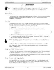
When mounting the sensing element to the process pipe, it is important that a lubricant/sealant be applied to the male<br />
threads of all connections. Be sure to use a lubricant/sealant compatible with the process environment. All<br />
connections should be tightened firmly. To avoid leaks, do not overtighten or cross-thread connections. See<br />
Figure 2-1 and the appropriate figure in Appendix A for proper mounting.<br />
Figure 2-1. NPT Pipe Thread Mount<br />
FLTÔ Series FlexSwitchÔ 2 - 2 Doc. No. 06EN003246 Rev. B
CHAPTER 2 - INSTALLATION<br />
FLUID COMPONENTS, INTL<br />
Flange Mounting<br />
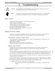
For flange mounted sensing elements, attach the process mating flange with care. The correct orientation of the<br />
sensing element must be maintained to ensure optimum performance or calibration. See Figure 2-2 and the<br />
appropriate drawings in Appendix A.<br />
Figure 2-2. Flange Mount<br />
Packing Gland Assembly<br />
Applications involving the use of a packing gland (low or medium pressure) should refer to the drawings in<br />
Appendix A for additional detail.<br />
1. Threaded or flanged packing gland mounts are available. The valve assembly with appropriate connections are<br />
customer supplied. Follow the male NPT mounting procedure above to attach the pipe thread portion or flange<br />
mounting portion as applicable.<br />
2. Tighten the packing nut until the internal packing is tight enough so that the friction fit on the shaft is adequate<br />
to prevent leakage but not prevent the shaft from sliding. Position the etched flow arrow parallel with the flow<br />
(±1° of level) and position the flow arrow so it is pointing in the direction of the flow.<br />
3. Proceed to insert the probe into the process media line. Use the adjusting nuts on the all-thread to pull the<br />
sensing element into proper predetermined depth position.<br />
4. Tighten the opposing lock nuts on the all-threads. Tighten the packing nut another half to full turn until tight<br />
(approximately 65 to 85 ft-lbs [88 to 115 N-m] torque).<br />
5. Rotate the split ring locking collar to line up with the connecting strap welded to the packing nut. Tighten the<br />
two 1/4-28 hex socket cap screws on the split ring locking collar.<br />
Reverse these steps for removal.<br />
In-line NPT Assembly (FLT93-L)<br />
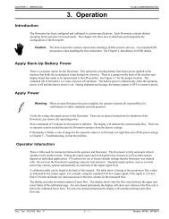
The body length of the in-line assembly should be verified to be sure the assembly will fit into the process line. See<br />
the appropriate figure in Appendix A to determine the assemblies length. The direction of flow is important for<br />
proper operation. There is a flow direction arrow on the in-line pipe that is to point in the direction of flow. See<br />
Figure 2-3 for the correct orientation.<br />
Doc. No. 06EN003246 Rev. B 2 - 3 FLTÔ Series FlexSwitchÔ
FLUID COMPONENTS, INTL<br />
CHAPTER 2 - INSTALLATION<br />
Sanitary Assembly (FLT93-C)<br />
Figure 2-3. FLT93-L In-line Flow Element<br />
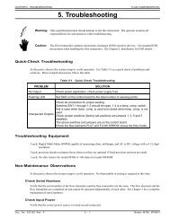
The instrument is inserted into the process connection with a removable clamp fittings. The Removable Clamp (RC)<br />
sanitary assembly contains a removable clamp connection to the flow element. The Clean-In-Place (CIP) sanitary<br />
assembly has the flow element directly welded into the process stand pipe. Otherwise these instruments function<br />
exactly the same as an FLT93-F or FLT93-S. See Appendix A for an outline dimensions of the instruments.<br />
Figure 2-4 also shows the sanitary assemblies.<br />
Figure 2-4. FLT93-C Sanitary Flow Elements (RC and CIP Respectively)<br />
Install and Wire the Enclosure(s)<br />
Caution:<br />
In applications where the sensing element is located in an explosive environment, isolate the conduit<br />
before it leaves the environment. A potting Y may be used to provide the isolation.<br />
Pulling wires can cause damage to the control circuit. Therefore, remove the control circuit from the<br />
enclosure and use extreme care when pulling wires into the enclosure.<br />
Mount and wire the control circuit either locally or remotely (option) by following the local or remote enclosure<br />
procedure below.<br />
Minimum Wire Size<br />
Table 2-1 shows the smallest (maximum AWG number) copper wire that is used in the electrical cables. Use a lower<br />
gauge of wire for less of a voltage drop. Contact FCI concerning greater distances than those listed in the table. The<br />
sensing element cable must be shielded. If the cable is spliced the shield wire must be continued through the splice.<br />
If a terminal block is used, the shield must have its own terminal.<br />
FLTÔ Series FlexSwitchÔ 2 - 4 Doc. No. 06EN003246 Rev. B
CHAPTER 2 - INSTALLATION<br />
FLUID COMPONENTS, INTL<br />
Table 2-1. Maximum AWG Number<br />
Maximum Distance for AWG<br />
Connection 10 ft.<br />
(3m)<br />
50 ft.<br />
(15m)<br />
100 ft.<br />
(31m)<br />
250 ft.<br />
(76m)<br />
500 ft.<br />
152m)<br />
1000 ft.<br />
(305m)<br />
AC Power<br />
22<br />
22<br />
22<br />
20<br />
18<br />
16<br />
Relay<br />
(2A)<br />
28<br />
22<br />
20<br />
16<br />
12<br />
10<br />
Flow Element Wires* 22<br />
20<br />
20<br />
18<br />
18<br />
18<br />
*Requires a shielded cable with the shield wire connected to the control socket only.<br />
Wiring the Local Enclosure<br />
This procedure is for instruments with the control circuit located in the sensing element enclosure.<br />
1. Remove the control circuit from its socket. Do not remove the control circuit socket. Removal of the control<br />
circuit socket may cause damage to the instrument.<br />
2. Install conduit between the local enclosure and the power source and monitoring circuit. Provide watertight<br />
hardware and apply thread sealant to all connections to prevent water damage.<br />
Warning:<br />
Ensure that all power is off before wiring any circuit.<br />
3. When connecting the relay wiring, do so with complete understanding of what the process requires of the<br />
instrument. The instrument has dual SPDT or single DPDT relay output contacts dependent on the jumper<br />
configuration for each alarm switch point. For the relay logic, refer to Figure 2-5. Also refer to Table 3-5 and<br />
Table 3-6 in <strong>Chapter</strong> 3 - Operation. Relay contacts are shown with the relays de-energized. Wire in accordance<br />
with the system requirements.<br />
Figure 2-5. Local Wiring Diagram<br />
Doc. No. 06EN003246 Rev. B 2 - 5 FLTÔ Series FlexSwitchÔ
FLUID COMPONENTS, INTL<br />
CHAPTER 2 - INSTALLATION<br />
Wiring The Remote Enclosure<br />
This procedure is for instruments with the control circuit located remotely from the sensing element.<br />
Locate the Remote Hardware Location<br />
Appendix A shows the remote enclosure along with the physical dimensions to properly mount it. Select a location<br />
for the remote enclosure within a 1000 feet (305 m) of the sensing element. Pigtail sensing elements can not be<br />
located more than 10 feet (3 m) from the enclosure unless the pigtail is extended with the proper size cable listed in<br />
Table 2-1. If the cable is extended the cable connections should be located in a junction box with a 6 position<br />
terminal block. All 5 conductors and the shield must have its own termination. The remote enclosure should be<br />
easily accessible with enough room to open the enclosure cabinet cover at any time. Secure the remote enclosure<br />
solidly to a vertical surface capable of providing support. Use appropriate hardware to secure the enclosure.<br />
1. Remove the control circuit from the remote enclosure.<br />
2. Run a five-conductor, shielded cable from the local enclosure to the remote enclosure. Use Table 2-1 to<br />
determine which wire gauge to use.<br />
3. Wire between the local and remote enclosures according to Figure 2-6.<br />
Warning:<br />
Ensure that all power is off before wiring any circuit.<br />
4. When connecting the relay wiring, do so with complete understanding of what the process requires of the<br />
instrument. The instrument has dual SPDT or single DPDT relay output contacts dependent on the jumper<br />
configuration for each alarm switch point. For the relay logic, refer to Figure 2-6. Also refer to Table 3-5 and<br />
Table 3-6 in <strong>Chapter</strong> 3 - Operation. Relay contacts are shown with the relays de-energized. Wire in accordance<br />
with the system requirements.<br />
Figure 2-6. Remote Wiring Diagram<br />
FLTÔ Series FlexSwitchÔ 2 - 6 Doc. No. 06EN003246 Rev. B
CHAPTER 2 - INSTALLATION<br />
FLUID COMPONENTS, INTL<br />
Figure 2-7. Auxiliary Relay Board Wiring Diagram<br />
Wiring Remote Enclosure with Auxiliary Relay<br />
Refer to the "Wiring the Remote Enclosure" section to run the cable between the local and remote enclosures. In<br />
most cases the auxiliary relay board is in the same enclosure as the control circuit. Both boards are mounted on the<br />
same panel and have been wired together at the factory. This configuration can be ordered without an enclosure<br />
which can be supplied by the customer.<br />
The alarm connections are made at the auxiliary relay board where each alarm is driving a DPDT relay.<br />
Caution:<br />
Do not connect any loads to the control circuit socket. Damage will occur to the control circuit if the<br />
alarm circuit is energized.<br />
Be sure the correct relay board has been ordered for the correct output. See the following paragraph.<br />
This configuration uses a control circuit that provides a switching voltage signal instead of relay contacts. The<br />
switch voltage is wired from the control circuit socket to the auxiliary relay board actuating the relays.<br />
The auxiliary relay board has several relay options that can be ordered. The options are as follows:<br />
• Dry to 2 amps at 115 Vac or 28Vdc, Dry to 1 amp at 230 Vac (relay is enclosed in a plastic sealed cover).<br />
• 100mA to 10mA at 115 Vac or 28Vdc, 50mA to 3 amps at 230 Vac (relay is enclosed in a plastic sealed cover).<br />
• Dry to 0.5 amps at 115 Vac, hermetically sealed relay.<br />
Doc. No. 06EN003246 Rev. B 2 - 7 FLTÔ Series FlexSwitchÔ
FLUID COMPONENTS, INTL<br />
CHAPTER 2 - INSTALLATION<br />
Make sure that the proper relays have been selected for the intended load. See Appendix A for the auxiliary relay<br />
board configuration drawing.<br />
When connecting the relay wiring, do so with complete understanding of what the process requires of the instrument.<br />
The instrument has dual DPDT or single 4PDT relay output contacts dependent on the jumper configuration for each<br />
alarm switch point. For the relay logic, refer to Figure 2-5. Also refer to Table 3-5 and Table 3-6 in<br />
<strong>Chapter</strong> 3 - Operation. Relay contacts are shown with the relays de-energized. Wire in accordance with the system<br />
requirements.<br />
The control circuit can be ordered with switching voltage outputs without ordering a relay board. This can be used<br />
with customer supplied relays or any other device that has a differential input. The output voltage is 17 Vdc and will<br />
drive a load as low as 1500 ohms. Refer to Figure 2-7 for the output terminals.<br />
Wiring A Remote Control Circuit To An Auxiliary Relay Board<br />
1. Run a four-conductor cable from the control circuit to the auxiliary relay board if the board was not factory<br />
installed. Use the wiring diagram in Figure 2-7 to wire the boards together.<br />
2. Attach the customer wiring as desired using Figure 2-7 as a wiring guide.<br />
Wiring for this configuration is the same as the sensing element wiring to the control circuit on a remote instrument.<br />
Wiring Output Signal Terminals<br />
Two output signals are provided on the control circuit at P1. The signal voltage at positions 1 and 2 represents the<br />
process change. The signal voltage at positions 3 and 4 is proportional to the temperature at the sensing element.<br />
See Figures 2-5 through 2-7. See also <strong>Chapter</strong> 3 for the physical layout of the control circuit.<br />
Caution:<br />
Do not ground terminal 2 of P1. (Terminal 2 is the negative lead of the process signal.) This terminal<br />
is 9 volts above the control circuit ground. The peripheral using this signal must have a differential<br />
input.<br />
These voltages can be used by other peripherals with a minimum load of 100K ohms. The terminal block can be<br />
wired with between gauge 26 and 18 wire (22 gauge wire is normally used). The maximum recommended length of<br />
wire is 1000 feet. Shielding is required on any length of cable. The shield must be terminated at position 4 on P1.<br />
Early versions of the FLT93 require a connecting harness that was supplied with each instrument. The harness can<br />
be ordered if it is missing. The FCI part number is 015664-01. Newer versions of the FLT93 require a supplied<br />
terminal plug.<br />
FLTÔ Series FlexSwitchÔ 2 - 8 Doc. No. 06EN003246 Rev. B