Manual Chapter 5 - Troubleshooting - Fluid Components International
Manual Chapter 5 - Troubleshooting - Fluid Components International
Manual Chapter 5 - Troubleshooting - Fluid Components International

Create successful ePaper yourself
Turn your PDF publications into a flip-book with our unique Google optimized e-Paper software.
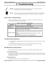
CHAPTER 5 - TROUBLESHOOTING5. <strong>Troubleshooting</strong>FLUID COMPONENTS INTLCaution:Only qualified personnel should attempt to test this instrument. The operator assumes allresponsibilities for safe practices while troubleshooting.Alert:The electronics contains electrostatic discharge (ESD) sensitive devices. Use standard ESDprecautions when handling the electronics. See <strong>Chapter</strong> 2, Installation for ESD details.Quick CheckVerify the serial numbers of the flow element and electronics match.Verify all cables are seated firmly.Verify all customer connections are correct.Verify the wiring is per the wiring diagram in <strong>Chapter</strong> 2.Verify the installation is correct as shown in <strong>Chapter</strong> 2.Check customer fuses and power switches.Press [P] to reconfigure the FC88 to the proper 2 line display.Press [N] to reset the software.General Function CheckOnce the flow meter has been installed and turned on, the instrument can be checked for proper operation byperforming the NAMUR functional checks. The following tools will be required for this check.Tools Needed - General Function Check -FC88 Communicator or Computer with Interface Kit - Contact a Field Representative or Customer Service topurchase an FC88 or computer interface kit.Digital Multimeter (DMM)Allen Wrench 1/16 Inch (for aluminum, circular enclosure)Medium size flat blade Screwdriver (for steel, square enclosure)NAMUR Fault IndicationNAMUR NE43 is a German fault detection standard that lets the user know if there is a fault within theinstrument. The fault indicator can be turned on or off with the X menu function as described in<strong>Chapter</strong> 3 - Operation.When the indicator is on and a fault is detected the 4-20 mA output will be driven to less than or equal to 3.5 mA,or 22 mA or greater, depending upon what the user chooses. If a voltage output was selected, the output will bedriven from 0 to 1 volt every 7 seconds. The voltage fault indicator is not part of the NAMUR NE43 standard.When the NAMUR Fault indication is turned on (Menu X), the faults will be displayed when the instrument is inthe normal operation mode (Menu T).In a few cases there may be two error indications when there is only one fault. A single fault can cause multipleproblems with the instrument, therefore there are more than one fault indications. The fault indications shown inthe T mode are prioritized in the order of where the problem will most likely be found.Example: Error codes are: "Sensor Error" "Overtemp Head"There is most likely a sensor element wiring problem that is creating an over temperature faultsituation.Doc. No. 06EN003291 Rev. A 5 - 1 Model ST98 Flow Meter
FLUID COMPONENTS INTLCHAPTER 5 - TROUBLESHOOTINGProcedureOpen the enclosure to expose the customer connection board.Connect the FC88 or computer to the RS-232 Jack (P1).Set the FC88 communicator or computer to display the T mode.Turn on the NAMUR fault flag (menu X).Compare the fault indication from the T mode with Table 5-1. Follow the instructions provided in the table.Table 5-1. NAMUR Fault ListingIndicated FaultsNothing displayed on the FC88or the optional display.No display on the FC88 no displayon the optional display.No display on the FC88. There is adisplay on the optional LCD display.No fault indicated. Output mA orVout operates correctly.No fault indicated but the 4-20 mA(or Voltage) output is nottransmitting.Sensor Error.OverTemp Head!!UnderTemp Head!!Open Heater!!Shorted Heater!!Possible CausesPower is not applied to the instrument. Power is not correctly applied tothe customer connection board. There is a green LED that lights when ACpower is applied. It is on the back side of the customer circuit board behindP1 (it is hard to see). If it is blinking remove power and contact customerservice.Press [P] [ENTER] on the FC88 to reset it. If there is no response connectit to another ST98 (if present) to verify operation. Replace the cablebetween the ST98 and the FC88 if there is no operation. If no operationcontact customer service.Verify the NAMUR option is activated [X] [ENTER]. If there is no faultindicated, verify the heater is on [H] [ENTER]. If there is no faultindicated, proceed to the installation and Application Verificationprocedure.Go to the Instrument Output Check procedure.Wiring to the sensing element may be incorrect. One or more of the senseor excitation wires may be disconnected or shorted. The active or referenceRTD is either open or shorted. Check the wiring (see Appendix A) and thesensor resistance as shown later in this chapter.The process temperature has exceeded the maximum temperature rating ofthe flow element (350°F). Verify the temperature of the process. If thetemperature is over 350°F, remove the flow element from the process.Damage to the flow element will occur. Contact customer service.The process temperature has exceeded the minimum temperature rating ofthe flow element (-50°F). Verify the temperature of the process. If thetemperature is under -50°F, remove the flow element from the process.Damage to the flow element will occur. Contact customer service.The flow element's heater has exceeded the maximum resistance allowed(approximately 170 ohms) or is disconnected. This limit also includes thecable resistance in remote installations. The heater fault flag will come onin cases when the heater is turned off (using the menu key [H] [ENTER]).Check the wiring and the sensor resistance.The flow element's heater has exceeded the minimum resistance allowed(approximately 90 ohms) or it is shorted. This limit also includes the cableresistance on remote installation. The heater fault flag will come onin cases when the heater is turned off (using the menu key [H] [ENTER]).Check the wiring and the sensor resistance.Model ST98 Flow Meter 5 - 2 Doc. No. 06EN003291 Rev. A
CHAPTER 5 - TROUBLESHOOTINGFLUID COMPONENTS INTLApplication VerificationAfter verifying that the flow meter is functioning, review the application parameters as shown below to verify thecalibration matches the process media.Equipment NeededFlow Instrument Calibration DataProcess Parameters and LimitsCheck Serial NumbersVerify that the serial number of the flow element and the flow transmitter electronics are the same. The flowelement and the flow transmitter are a matched set and cannot be operated independently of each other.Check the Instrument InstallationReview the information in <strong>Chapter</strong> 2 - Installation, to verify correct mechanical and electrical installation.Verify that the flow element is mounted at least 20 diameters downstream and 10 diameters upstream from anybends or interference in the process pipe or duct.Check for MoistureCheck for moisture on the flow transmitter. Moisture on the flow transmitter may cause intermittent operation.Check for moisture on the flow element. If a component of the process media is near its saturation temperature itmay condense on the flow element. Place the flow element where the process media is well above the saturationtemperature of any of the process gases.Check Application Design RequirementsApplication design problems may occur with first time application instruments, although the design should also bechecked on instruments that have been in operation for some time. If the application design does not match fieldconditions, errors occur.1. Review the application design with plant operation personnel and plant engineers.2. Ensure that plant equipment such as pressure and temperature instruments conform to the actual conditions.3. Verify operating temperature, operating pressure, line size, and gas medium.Verify Standard Versus Actual Process ConditionsThe flowmeter measures the mass flow rate. The mass flow rate is the mass of the gas flowing through a pipe pertime. Other flow meters, such as an orifice plate or a pitot tube, measure the volumetric flow rate. The volumetricflow rate is the volume of gas per time. If the readings displayed do not agree with another instrument, somecalculations may be necessary before comparing them. To calculate the mass flow rate, the volumetric flow rate,and the pressure and temperature, the point of measurement must be known. Use the following equation tocalculate the mass flow rate (Standard Volumetric Flow rate) for the other instrument:Equation:PATSQ = Q × ×S A(Metric: Where bar(a) and °K are usedT PASWhere:for pressure and temperature.)Q A= Volumetric Flow Q S= Standard Volumetric FlowP A= Actual Pressure T A= Actual TemperatureP S= Standard Pressure T S= Standard TemperaturePSIA and °R are used for pressure and temperature units.Doc. No. 06EN003291 Rev. A 5 - 3 Model ST98 Flow Meter
FLUID COMPONENTS INTLCHAPTER 5 - TROUBLESHOOTINGExample:(Metric: P S= 1.01325 bar(a)Q A= 1212.7 ACFM Q S= 1485 SCFM T S= 21.1°C (294.1K))P A= 19.7 PSIA T A= 120°F (580°R)P S= 14.7 PSIA T S= 70°F (530°R)1212.7 ACFM 19.7 PSIA 530° R .( 1 )( 580° R )( 14.7 PSIA )= 1485 SCFMVerify the Calibration ParametersThe instrument uses a set of predetermined calibration parameters to process flow signals. Most of theseparameters should not change. A data package located at the rear of this manual contains the “ST98 Delta R DataSheet”. This contains the calibration ST98 parameters stored in the flow transmitter at the factory. To verify thatthese parameters have not changed, complete the following:1. Identify the appropriate Delta R Data sheets by serial number of the instrument.2. Press [D] [ENTER] to examine each of the parameters. The [ENTER] key allows scrolling one message at atime. Use Table 5-2 to verify parameters with the Delta R Data sheet ST98 Parameters.Table 5-2. Diagnostic Test Sequence on DisplayS erial No.eu:C ust. No.curvefit:s cale:outmode:* c1:*maxflow:* c2:*minflow:* c3:*Max A/D:* c4:tot:* c5:tflow:* c6:*Min A/D:* c7:*Density:* c8:K-Factor:* c9:zero:* c10*sensor:* caltemp:*tslp:* balance:*tcslp0:* outz:*tcslp:* outf:*tcslp2:* heater i:line size0* toff:line size1:f actor:F.S. :If parameters that have an asterisk (*) have changed, this may indicate a problem. Customer Service should becontacted. If the parameters have not changed, continue with the next section.Model ST98 Flow Meter 5 - 4 Doc. No. 06EN003291 Rev. A
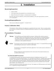
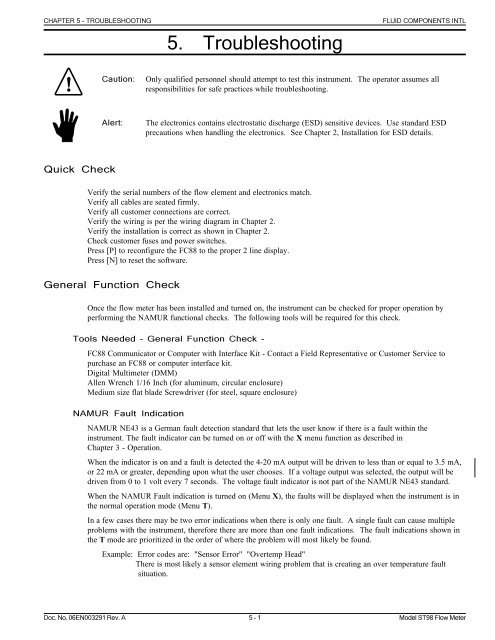
CHAPTER 5 - TROUBLESHOOTINGFLUID COMPONENTS INTLCheck the HardwareEquipment RequiredFC88 Communicator or Computer with Interface Kit - Contact a Field Representative or Customer Service topurchase an FC88 or computer interface kit.Digital Multimeter (DMM)Allen Wrench 1/16 Inch (for aluminum, circular enclosure)Flat blade Screwdriver (for steel, square enclosure)<strong>Troubleshooting</strong> the Flow ElementUse Table 5-3 to determine if the flow element is wired correctly or has failed. Table 5-3 is for resistances at aprocess temperature of about 70 degrees. To determine the exact resistance at another process temperature use thetemperature versus resistance table in Appendix A.Turn off the input power to the instrument. Unplug TS2 from the circuit board assembly and measure theresistances as shown in Table 5-3.See Figure 5-1 for component placement and Figure 5-2 for a view of the plug. If the instrument is set up in aremote configuration (flow element enclosure separate from the control circuit enclosure), and the ohm readingsare incorrect disconnect the flow element cable at the local (flow element) enclosure. Measure the resistance asshown in Table 5-3. Figure 5-3 shows the terminal block configuration.If the resistance is correct then the cable between the enclosures is probably bad or not connected properly(loose, corroded, or connected to the wrong terminal).ENCLOSURETP1TS2P4EPROMP5P3Figure 5-1. Component IdentificationGND SENRTD GND REF SENACT SENREF EXCACT EXCHTR EXCHTR RTNRTD GNDGND SENREF SENACT SENREF EXCACT EXCHTR EXCHTR RTNFigure 5-2. TS2 Connector PlugFigure 5-3. Terminal Block In Local EnclosureDoc. No. 06EN003291 Rev. A 5 - 5 Model ST98 Flow Meter
FLUID COMPONENTS INTLTable 5-3. Flow Element Resistance at TS2 or Local Terminal BlockLUG OR PIN NUMBER RESISTANCE(7) HTR EXC TO (8) HTR RTN 110 - 118 OHMS(4) ACT SEN TO (2) GND SEN 1.1K OHM(3) REF SEN TO (2) GND SEN 1.1K OHM(3) REF SEN TO (4) ACT SEN 2.2K OHMS(1) RTD GND TO (2) GND SEN 0 OHMS(4) ACT SEN TO (6) ACT EXC 0 OHMS(3) REF SEN TO (5) REF EXC 0 OHMSSHIELD TO HTR RTN (8) (REMOTE INSTALLATIONS)CHAPTER 5 - TROUBLESHOOTINGThe resistance of the Active and Reference sensor will depend on the temperature of the sensing element. Refer tothe "Temperature Versus Resistance" Table in Appendix A.When measuring the resistance of the flow element through a long remote cable, the cable resistance must besubtracted from the measurement. The residual resistance of the DVM and its leads should also be considered.See Table 5-4 to calculate the resistance for copper wire. Each wire gauge size number increase represents a factorof 1.26 resistance increase over the previous size. Moving three gauge sizes higher doubles the resistance. Toconvert the table values to ohms per meter, multiply the value by 0.0394.Table 5-4. Resistance Versus Wire Size (AWG)Check the Flow Element VoltagesAWG SizeOhms Per 1000 Feet14 2.5215 3.1816 4.0217 5.0518 6.3919 8.0520 10.121 12.822 16.223 20.324 25.7Use the following voltage measurements if power cannot be easily removed from the instrument or if resistancemeasurement fail to resolve the problem. Be sure the sensor heater current is set to 75 mA LO by pressing [O] onthe FC88 and selecting the heater current. Be sure to set the heater current back to where it was before beginningthis procedure. Make the voltage measurements found in Table 5-5 at terminal strip TS2 on the flow transmitter,or on the Local Terminal Block.Table 5-5. Approximate Flow Element Voltages AT 70° FLUG OR PIN NUMBER VOLTAGE*(7) HTR EXC TO (8) HTR RTN Approximately 6.79 VDC(4) ACT SEN TO (6) ACT EXC Approximately 0.00 VDC(3) REF SEN TO (5) REF EXC Approximately 0.00 VDC(5) REF EXC TO (1) RTD GND Approximately 2.20 VDC(6) ACT EXC TO (1) RTD GND Approximately 2.21 - 2.82 VDC**(4) ACT SEN TO (3) REF SEN Approximately 0.24 VDC**Cable resistance of the remote flow element will affect the TS2 voltage readings at theelectronics enclosure.*Voltages varies with Temperature and Flow and the Sensor Heater Current Selection.**Voltage will vary with the process flow rate.Model ST98 Flow Meter 5 - 6 Doc. No. 06EN003291 Rev. A
CHAPTER 5 - TROUBLESHOOTINGVerification Of The ElectronicsFLUID COMPONENTS INTLCheck the Flow Transmitter VoltagesCheck the voltages in Table 5-6 being sure the volt meter is in the volt mode. Using the DVM in the current modewill damage the flow transmitter.Table 5-6. Instrument VoltagesPIN NUMBER VOLTAGEP3-1 TO P3-5 -9 TO -5 VDCP3-1 TO P3-6 +5 ± 0.2 VDCP3-1 TO P3-11 +2 ± 0.01 VDCTP1 +15 TO TP1 GND +15 ± 0.5 VDCTP1 +20 TO TP1 GND +20 ± 0.5 VDCTP1 +10 TO TP1 GND +10 ± 0.01 VDCIf the voltage checks correspond to Table 5-6, the electronics are functioning properly.Transmitter Circuit Calibration Check (Delta R Verification)Equipment NeededFC88 Communicator or equivalentDVMOriginal Delta R Data Sheet - Match By Serial Numbers2 Precision Decade Resistance Boxes, 0.1% (Largest Steps: 1K Ohm, Smallest Steps 0.01 Ohms)10 feet of wire, 22 to 18 AWGSmall Flat Blade Screwdrivers, 3/32 and 1/8 inches wide blades.Small Wire CuttersSmall Wire StrippersProcedure1. Turn power off.2. Mark all wires connected to terminal strip TS2 (or the terminal block for remote instruments) so they may bereconnected to the proper terminals. Disconnect the wires.3. Connect the resistance decade boxes to terminal strip TS2 (or the terminal block for remote instruments) asshown in Figure 5-4. Check the Delta R Data sheet for the nominal resistance value. Set the decade boxes forthe nominal resistance value ±0.01%.4. Turn the power on and allow the instrument 5 minutes to stabilize.5. Press [T] [ENTER] to view the normal operating mode. Adjust the active and reference decade boxes. Verifythe parameters on the FC88 change.If the display changes, proceed to the next section. If the display is frozen the instrument is malfunctioning.Contact Customer Service.Doc. No. 06EN003291 Rev. A 5 - 7 Model ST98 Flow Meter
FLUID COMPONENTS INTLCHAPTER 5 - TROUBLESHOOTINGFigure 5-4. Decade Box ConnectionsInstrument Output CheckAlert:If the mA output is being used on the flow transmitter, the receiver must have a resistance rangeof 0 to 700 ohms, including the cable resistance.To vary the output, follow the procedure below:1. Press [I] then [ENTER] on the FC88. "Enter #(0 01000)" will be displayed on the FC88. Press [0] forminimum output or [500] for an output that is in the center of the range or [1000] for a maximum output.2. Check the receiver and verify that it agrees with what is being sent.3. When the above step is verified press [ENTER].If the receiver is not responding to the signal being sent, remove the power from the instrument. Disconnect theoutput cable (TS3) and connect a current meter to "mA OUT". Apply power to the instrument and go through the[I] routine to check the output locally. If the mA output responds correctly then there is a problem with the cableor receiver. If there is no response form the mA output, there may be a configuration error or the output circuit isinoperative.The voltage output option can also be checked with the [I] menu and can help solve problems with the 4-20 mAoutputAlert:When finished with troubleshooting be sure that environmental seals are intact and properlyinstalled when securing enclosure lids. Damage resulting from moisture penetration of the Localor Remote Enclosure is NOT covered by product warranty.SparesFCI recommends one of each of the following should be kept as a spare: One identically set up ST98 Flow meter.Contact FCI for specific recommendations.Model ST98 Flow Meter 5 - 8 Doc. No. 06EN003291 Rev. A
CHAPTER 5 - TROUBLESHOOTINGFLUID COMPONENTS INTLDefective PartsBefore returning any equipment to FCI, please obtain an RA number for authorization, tracking, and repair/replacement instructions. If a return is required, remove defective instrument, replace with spare, calibrate, thenreturn defective instrument to FCI freight prepaid for disposition.Customer Service1. In the event of problems or inquiries regarding the flowmeter, please contact the regional or countryauthorized FCI Field Agent. There is an extensive list of these representatives at the front of this manual.2. Before contacting the FCI representative, please be sure that all the applicable information is near so that amore effective, efficient and timely response may be provided.3. Refer to Appendix C for specific Customer Service policy provisions.Doc. No. 06EN003291 Rev. A 5 - 9 Model ST98 Flow Meter
FLUID COMPONENTS INTLCHAPTER 5 - TROUBLESHOOTINGModel ST98 Flow Meter 5 - 10 Doc. No. 06EN003291 Rev. A