Manual Chapter 5 - Troubleshooting - Fluid Components International
Manual Chapter 5 - Troubleshooting - Fluid Components International
Manual Chapter 5 - Troubleshooting - Fluid Components International

Create successful ePaper yourself
Turn your PDF publications into a flip-book with our unique Google optimized e-Paper software.
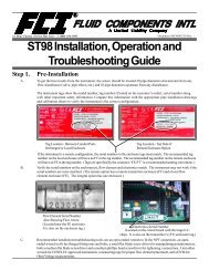
CHAPTER 5 - TROUBLESHOOTING<br />
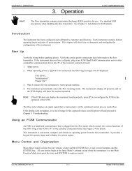
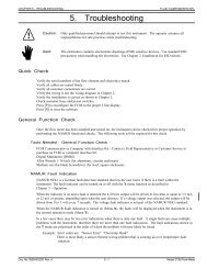
5. <strong>Troubleshooting</strong><br />
FLUID COMPONENTS INTL<br />
Warning:<br />
Only qualified personnel should attempt to test this instrument. The operator assumes all<br />
responsibilities for safe practices while troubleshooting.<br />
Caution:<br />
The flow transmitter contains electrostatic discharge (ESD) sensitive devices. Use standard ESD<br />
precautions when handling the flow transmitter. See <strong>Chapter</strong> 2, Installation, for ESD details.<br />
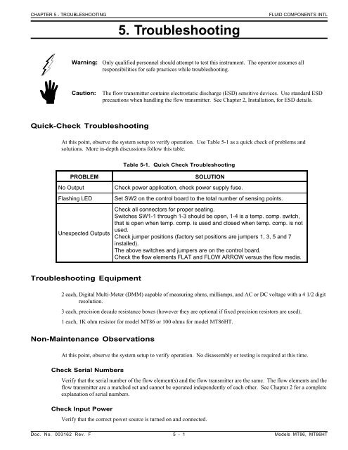
Quick-Check <strong>Troubleshooting</strong><br />
At this point, observe the system setup to verify operation. Use Table 5-1 as a quick check of problems and<br />
solutions. More in-depth discussions follow this table.<br />
Table 5-1. Quick Check <strong>Troubleshooting</strong><br />
PROBLEM<br />
No Output<br />
Flashing LED<br />
Unexpected Outputs<br />
SOLUTION<br />
Check power application, check power supply fuse.<br />
Set SW2 on the control board to the total number of sensing points.<br />
Check all connectors for proper seating.<br />
Switches SW1-1 through 1-3 should be open, 1-4 is a temp. comp. switch,<br />
that is open when temp. comp. is used and closed when temp. comp. is not<br />
used.<br />
Check jumper positions (factory set positions are jumpers 1, 3, 5 and 7<br />
installed).<br />
The above switches and jumpers are on the control board.<br />
Check the flow elements FLAT and FLOW ARROW versus the flow media.<br />
<strong>Troubleshooting</strong> Equipment<br />
2 each, Digital Multi-Meter (DMM) capable of measuring ohms, milliamps, and AC or DC voltage with a 4 1/2 digit<br />
resolution.<br />
3 each, precision decade resistance boxes (however they are optional if fixed precision resistors are used).<br />
1 each, 1K ohm resistor for model MT86 or 100 ohms for model MT86HT.<br />
Non-Maintenance Observations<br />
At this point, observe the system setup to verify operation. No disassembly or testing is required at this time.<br />
Check Serial Numbers<br />
Verify that the serial number of the flow element(s) and the flow transmitter are the same. The flow elements and the<br />
flow transmitter are a matched set and cannot be operated independently of each other. See <strong>Chapter</strong> 2 for a complete<br />
explanation of serial numbers.<br />
Check Input Power<br />
Verify that the correct power source is turned on and connected.<br />
Doc. No. 003162 Rev. F 5 - 1 Models MT86, MT86HT
FLUID COMPONENTS INTL<br />
Check Instrument Installation<br />
CHAPTER 5 - TROUBLESHOOTING<br />
Review the instrument installation information given in <strong>Chapter</strong> 2 to verify correct mechanical and electrical<br />
installation. Be sure the connectors are firmly mated, and the wires are firmly attached to the connector. (Be sure<br />
the wires are inserted between the metal clamps and not between the clamp and plastic connector enclosure.)<br />
Check for Moisture<br />
Check for moisture in the enclosures. Moisture on the electronics can cause faulty operation.<br />
If a component of the process media is near its saturation temperature, then the component may condense on the<br />
sensing points. Liquid on the sensing points will drive the flow measurement higher than the true measurement.<br />
Check Application Design Requirements<br />
Application design problems usually occur with first time application instruments, although the design should also be<br />
checked on instruments that have been in operation for some time. If the application design does not match field<br />
conditions, errors occur.<br />
1. Review the application design with plant operation personnel and plant engineers.<br />
2. Ensure that plant equipment such as pressure and temperature instruments conform to the actual conditions.<br />
3. Verify operating temperature, operating pressure, line size, and gas medium.<br />
Check Flow Element Placement<br />
If there are measurement errors check for process flow irregularities. A swirling or pulsating flow can exist near<br />
valves, elbows and other obstructions. The flow element should be placed in a straight pipe run with 20 pipe<br />
diameters upstream of the flow element, and 10 pipe diameters down stream of the flow element.<br />
Check Flow Element Orientation<br />
Verify that the FLAT on the flow element is parallel to the pipe and the FLOW ARROW points in the direction of<br />
the flow stream. If the FLAT and the FLOW ARROW are not correct, the flow measurement will not be correct.<br />
See <strong>Chapter</strong> 2 for the instructions on proper installation.<br />
Check Proper Flow Element Insertion Depth<br />
The flow element's sensing points must be located at the center line of the pipe unless the factory specifies otherwise.<br />
Improper insertion depth may cause error in the flow measurement. See <strong>Chapter</strong> 2 for the instructions on proper<br />
installation.<br />
Check Flowmeter Switch Positions<br />
Switches SW1-1, SW1-2 and SW1-3 should be in the open position. Switch SW1-4 should be in the open position if<br />
the temperature compensation mode is used. Switch SW1-4 should be in the closed position if temperature<br />
compensation is not being used. An easy way to verify temp. comp. is used is to see if the top of the null and gain<br />
potentiometers have been sealed. If they are sealed the flowmeter is setup to use temperature compensation. If they<br />
are not then no temperature compensation is used. (An open switch is the switch depressed on the left or lower side<br />
of the switch bank.<br />
Verify that the head-select switch SW2 is set on the number that corresponds to the last sensing point that is<br />
connected to the flow transmitter.<br />
Verify that the switch SW4 is in the OP position.<br />
<strong>Troubleshooting</strong> Process<br />
Verify Delta " R" Sheets<br />
Verify that the Delta "R" sheets in the rear of this manual match the flowmeter's serial number. If there is a<br />
miss-match the calibration could be incorrect. Contact FCI if the proper Delta "R" Sheets are missing.<br />
Models MT86, MT86HT 5 - 2 Doc. No. 003162 Rev. F
CHAPTER 5 - TROUBLESHOOTING<br />
Verify Faulty Flow Elements<br />
FLUID COMPONENTS INTL<br />
Caution:<br />
Inform all personnel involved with monitoring the flow media that the flowmeter output readings<br />
may change. The change of output could affect the plant peripheral equipment and or alarms.<br />
To identify a bad flow element rotate the Head-Select switch, SW2, through its numbered positions. Pause at each<br />
position to monitor a red Light Emitting Diode (LED), CR1. CR1 is located on the MT86 Control Board. If a<br />
problem exists with a sensing point, the LED will flash. The LED may also flash if there is no sensing point that<br />
corresponds to the switch position. If the Head-Select switch is pointing to a valid sensing point and the LED is<br />
flashing the sensing point is bad.<br />
Verify Resistance Readings<br />
Use Figure 5-1 and Table 5-2 to determine if the flow elements are wired incorrectly or have failed. Turn the power<br />
OFF to the flow transmitter. Unplug the problem flow element at the Input Board. Measure the resistances<br />
described below by touching the DMM test leads to the terminal screws. (Remember to reconnect the flow element<br />
when the troubleshooting is finished.)<br />
Note:<br />
If the system process does not allow the flowmeter power to be disconnected or the flow elements to be<br />
unplugged then proceed to the section, In-Depth <strong>Troubleshooting</strong> - Voltage Measurements.<br />
All resistances in Table 5-2 are based on a temperature of 32°F ( 0°C). Resistances across the ACT and the REF<br />
RTDs for an MT86 are approximately 1000 ohms, resistances for an MT86HT are approximately 100 ohms. The<br />
resistances will continue to increase for higher temperatures at the sensing points. Resistance values will vary with<br />
temperature.<br />
Table 5-2. Terminal Plug Resistances<br />
Pin<br />
Number<br />
Approximate<br />
Resistances<br />
2 to 3 1000 Ohms*<br />
2 to 4 1000 Ohms*<br />
2 to 5 1000 Ohms*<br />
2 to 6 1000 Ohms*<br />
8 to 7 220 Ohms<br />
Figure 5-1. Terminal Plug<br />
*For the MT86HT flow element divide by 10.<br />
The resistance of the active RTD will be greater than the resistance of the reference RTD whenever the heater is on<br />
and the flow rate is below the high-limit flow. Also if the flowmeter has been on for some time, the resistance of the<br />
active RTD will be greater than the reference until it cools down.<br />
The flow element cable has a shield that ONLY connects to the flow transmitter side of the cable. There is no shield<br />
connected to the flow element.<br />
If one sensing point appears to be an open circuit and the other sensing point appears to be twice the resistance, a<br />
wiring problem probably exists.<br />
Voltage and current checks can be made on the flow elements. Before checking the flow element voltages and<br />
current, other voltages need to be verified first. See the following paragraphs for the proper sequence of checks to<br />
make.<br />
If the flow element is bad, replace it with a spare flow element. Return the bad flow element to FCI for repair and, or<br />
replacement. See Appendix C for the Customer Service return procedure.<br />
Doc. No. 003162 Rev. F 5 - 3 Models MT86, MT86HT
FLUID COMPONENTS INTL<br />
<strong>Troubleshooting</strong> Process - Voltage Measurements<br />
CHAPTER 5 - TROUBLESHOOTING<br />
Verify the use of the correct power source. Verify the power source is on and that the wiring matches the wiring<br />
diagram in Figure 2-2 of <strong>Chapter</strong> 2.<br />
If the flow element resistance and wiring check out, recheck the power supply; the fuse and the AC and DC voltages.<br />
The power supply should be suspect when there seems to be multiple failures in the flowmeter.<br />
Perform the following voltage checks with power applied to the flowmeter. The flowmeter should be put in normal<br />
operating conditions. Make all measurements with the use of a DMM that has a differential (non-grounded) input.<br />
Note:<br />
The flow element sensing point voltage readings are for 1000 ohm RTDs.<br />
Power Supply Source Voltages<br />
Measure the power source at the power supply terminal block TS1 to be sure the correct power is applied.<br />
Check the power supply voltages, using the test points provided. See Table 5-3 and Figure 5-2 for the proper operating<br />
voltages. If the voltage checks are correct, the power supply is functioning properly.<br />
Table 5-3. Power Supply Voltages - Power Supply Board<br />
POSITIVE LEAD (+) NEGATIVE LEAD (-) MEASURED VALUE<br />
TP1 TP4 28 Vdc ±1 Vdc<br />
TP2 TP4 15 Vdc ±.6 Vdc<br />
TP3 TP4 5 Vdc ±.3 Vdc<br />
TP5 TP4 -5 Vdc ±.3 Vdc<br />
TP6 TP4 -15 Vdc ±.6 Vdc<br />
VC6 VGND -26.43 Vdc ±1 Vdc*<br />
VC1 VGND 43.4 Vdc ±2 Vdc*<br />
*Measurement points are not available on some power supplies.<br />
If operating power is at terminal block TS1 and the test points do not have power, check fuse F1 on the power supply<br />
board.<br />
Remove power and unplug the power supply from the control board. Apply power to the power supply and re-measure<br />
the voltages as shown in Table 5-4. If the voltage is still missing, then remove and replace the power supply.<br />
Make the following measurements at the control board terminal strip. See Figure 5-3 and Table 5-4 for the<br />
measurements.<br />
Table 5-4. Power Supply Voltages - Control Board<br />
Positive Lead (+) Negative Lead (-) Measured Value<br />
TP15 TP16 10 Vdc ±.02 Vdc<br />
RN1 PIN 3 TP16 5 Vdc ±.04 Vdc<br />
U5 PIN 7 TP16 -10 Vdc ±.06 Vdc<br />
Models MT86, MT86HT 5 - 4 Doc. No. 003162 Rev. F
CHAPTER 5 - TROUBLESHOOTING<br />
FLUID COMPONENTS INTL<br />
Figure 5-2. Electrical Assembly Layout<br />
Doc. No. 003162 Rev. F 5 - 5 Models MT86, MT86HT
FLUID COMPONENTS INTL<br />
CHAPTER 5 - TROUBLESHOOTING<br />
Figure 5-3. Control Board Layout<br />
Models MT86, MT86HT 5 - 6 Doc. No. 003162 Rev. F
CHAPTER 5 - TROUBLESHOOTING<br />
FLUID COMPONENTS INTL<br />
If a voltage is missing, unplug all the input and output boards. Measure the voltage again to see if the voltage has<br />
returned. If it has returned plug in the boards one at a time until the board is found that is loading the circuit.<br />
Remove and replace the board. If the voltage does not return, replace the control board.<br />
Flow Element Operating Voltages<br />
Close switch SW1-1. All output signals should go to the minimum signal level. Return switch SW1-1 to the open<br />
position after testing. Make the following measurements at the input board terminal strip. See Table 5-5 and<br />
Figure 5-1 for the measurements.<br />
Table 5-5. Input Board Terminal Voltage Check<br />
Positive Lead Negative Lead Measured Value<br />
(+) (-) MT86 MT86HT<br />
HTR + HTR - 16.5 Vdc 16.5 Vdc ±1%<br />
REF SEN GND SEN 1.10 Vdc 0.275 Vdc*<br />
REF EXC GND SEN 1.10 Vdc 0.275 Vdc*<br />
ACT SEN GND SEN 1.25 Vdc 0.275 Vdc*<br />
ACT EXC GND SEN 1.25 Vdc 0.275 Vdc*<br />
*The above readings are at 80°F (27°C) and 14.7 PSIA and at no-flow. The readings will vary with temperature and<br />
flow. However, the reference voltages should always match and the active voltages should always match. The active<br />
voltages should be higher than the reference voltages.<br />
<strong>Troubleshooting</strong> Process - Flow Element Current<br />
To measure the currents put a DMM in series with the desired lead. See Table 5-6 for the measurements.<br />
Table 5-6. Current Measurements<br />
Measured Value (mA DC)<br />
Component<br />
MT86<br />
MT86HT<br />
REF SEN O.OO O.OO<br />
ACT SEN O.OO O.OO<br />
REF EXC 1.OO 2.5O<br />
ACT EXC 1.OO 2.5O<br />
HTR + 75.O ±5% 75.O<br />
If there are no problems, the flow elements are good. Further trouble shooting must concentrate outside of this area.<br />
Go to the following sections.<br />
Field Calibration Techniques<br />
The flowmeter circuit cards and the flow element can be replaced as separate items. A field calibration is needed<br />
after the replacement of the parts.<br />
Doc. No. 003162 Rev. F 5 - 7 Models MT86, MT86HT
FLUID COMPONENTS INTL<br />
Warning:<br />
CHAPTER 5 - TROUBLESHOOTING<br />
Only qualified personnel should test or repair the instrument. The operator assumes all<br />
responsibilities for safe practices while trouble shooting. Damage due to negligence or lack of<br />
technician skill is not covered by the warranty.<br />
Note:<br />
If field repair is attempted, replacement parts must be of the same part, type and number.<br />
Calibration Verification Procedure (Using Decade Boxes)<br />
Note:<br />
ALL MT86 flowmeters have 1000 ohm RTD sensing points.<br />
ALL MT86HT flowmeters (high temperature flow elements) have 100 ohm RTD sensing points.<br />
Determine which MT86 model type is present and use the ohm value that corresponds to the model<br />
type.<br />
Verify each sensing point one at a time. Select the manual operation mode of the flow transmitter by closing switch<br />
SW1-3. When the flowmeter is in the manual mode, the flow transmitter monitors only the sensing point that the<br />
head-select switch SW2 selects.<br />
Refer to the Delta "R" table for:<br />
1. Delta "R" value in ohms<br />
2. Vdc across 250 ohms<br />
3. Milliamp output signal values<br />
4. Raw signal (un-linearized)<br />
5. 0-10 Vdc analog output signal<br />
6. Display flow rate reading (in customer units) for each signal<br />
Apply the recorded Delta "R" input values to the selected input terminal on the input board. Having the correct data<br />
sheet for the correct input terminal is important.<br />
Procedure<br />
If an FC81 Field Calibrator is used, then go to the verification with a field calibrator procedure.<br />
1. Turn OFF the power to the instrument. Disconnect the flow element cable from the input board terminal<br />
block TS1.<br />
2. Connect two decade boxes or one decade box and a fixed resistor to terminal block TS1 (or TS2 as applicable)<br />
on the input board as shown in the diagram of Figure 5-4.<br />
3. Connect the positive lead of the DMM to the jumper J8 or to test point TP13 located at the bottom of the control<br />
board. Connect the negative lead to the signal ground TP5(-). This readout is the analog signal, 0-10 Vdc, that<br />
is before the span and zero activation circuitry.<br />
4. Close switch SW1-3 that puts the flow transmitter in the manual mode; this enables the head-select switch SW2<br />
to select and monitor one sensing point.<br />
5. Verify that switch SW4 near the bottom of the control board is in the OP (OPerate) position.<br />
6. Set the head-select switch SW2 to position number one; this selects the terminal block TS1 input where the<br />
decade boxes are connected.<br />
7. Set the decade box for the reference sensing point to 1000.00 ohms (100.00 ohms for HT).<br />
8. Refer to the Delta "R" Data Sheet and set the decade box for the active sensing point to 1000.00 ohms (100.00<br />
ohms for HT) plus the recorded Delta "R" resistance value for each sensing point that is designated by SN - #.<br />
Models MT86, MT86HT 5 - 8 Doc. No. 003162 Rev. F
CHAPTER 5 - TROUBLESHOOTING<br />
FLUID COMPONENTS INTL<br />
Figure 5-4. Decade Box Wiring Diagram<br />
9. Turn the power ON and let the system stabilize for 1 minute. If the LED (CR1) is flashing, recheck the wiring<br />
per <strong>Chapter</strong> 2.<br />
10. Read the signal displayed on the DMM. It should be equal to the signal value recorded on the Delta "R" Data<br />
Sheet ± 0.20 Vdc.<br />
11. Repeat the above steps for other values on the Delta "R" Data Sheet. Adjust the active decade box to give one<br />
of the recorded output signals. Then, determine what the Delta "R" value setting is and compare it with the<br />
recorded value from the Delta "R" Data Sheet. The Delta "R" values should be equal to within ± 1.25%.<br />
12. Repeat this verification procedure for each of the sensing points in the system. Be sure to use the proper Delta<br />
"R" Data Sheet for each sensing point being verified.<br />
13. Upon completion of the verification procedure, set the head-select switch SW2 to the number of sensing points<br />
present in the system. The flow transmitter only scans the number of flow elements set on head-select switch<br />
SW2. Open SW1-3 for the automatic mode. Leaving these switches set in the wrong positions will cause an<br />
operation error.<br />
Calibration Verification Procedure (Using an FC81 Field Calibrator)<br />
Note: All output modules and display options operate from the same 0-10 Vdc analog output signal. If the<br />
optional span and zero activation circuitry has been added to the output signal, then the Delta "R" Data<br />
for the output modules and displays will not match the values recorded on the Delta "R" Data Sheet.<br />
See the jumper listing in Table 3-1 to determine if the span and zero activation circuitry option has<br />
been added to the output signal circuitry.<br />
The FC81 Field Calibrator replaces the decade resistance boxes and the DMM that are used in the verification<br />
procedure. The field calibrator can switch its readout between the Delta "R" resistance values and the output signal.<br />
The use of the field calibrator requires having the correct Delta "R" Data Sheets for each flow element. The field<br />
calibrator is ideal for the field verification of MT86 and MT86HT installations.<br />
Model FC81-8 is used for the MT86 with 1000 ohm flow element sensing point RTDs.<br />
Model FC81-7 is used for the MT86HT with 100 ohm flow element sensing point RTDs.<br />
Doc. No. 003162 Rev. F 5 - 9 Models MT86, MT86HT
FLUID COMPONENTS INTL<br />
CHAPTER 5 - TROUBLESHOOTING<br />
FC81 Field Calibrator Control Functions<br />
The display shows the Delta "R" values or the output signal level depending on the position of the function switch.<br />
The function switch, is a 2 position push-button switch, located on the left front panel of the FC81 field calibrator.<br />
When the function switch is pressed to the in position the Delta "R" input resistance is displayed in ohms.<br />
When the function switch is pressed to the out position the output signal is displayed in volts (0-10 Vdc).<br />
Note:<br />
Follow the instructions on the front panel of the FC81 field calibrator to read the digital display.<br />
Ohms Adjust<br />
On the right side of the front panel is a 10-turn potentiometer that is used to input the desired Delta "R" resistance<br />
values.<br />
Add Ohms Switch<br />
A Delta "R" value may be more than the maximum value of the ohms adjust potentiometer. If this happens, there is<br />
another push-button switch on the right hand side of the panel that adds a fixed resistance to the displayed value.<br />
If an MT86HT has a Delta "R" value greater than 10 ohms, use the add ohm switch.<br />
If an MT86 has a Delta "R" value greater than 100 ohms, use the add ohm switch.<br />
The display's readout does not show the ohms added. The ohms added MUST be added to the displayed resistance<br />
for determination of the actual applied Delta "R". The ohms added and the displayed value MUST be combined to<br />
get the actual Delta "R" value.<br />
Connector Receptacle<br />
On the rear panel of the field calibrator is an AMP brand receptacle with round post connectors for the test cable.<br />
FC81 Field Calibrator Operating Procedure<br />
1. This procedure adjusts the Delta "R" values to give a recorded output signal. Then Delta "R" value reading is<br />
compared to the recorded value. This procedure verifies the proper operation of the flow transmitter. Be sure to<br />
have the correct Delta "R" Data Sheet by checking the serial number of the flow element and the serial number<br />
on the sheet.<br />
2. Turn OFF the power to the flowmeter. Record where the jumpers are on the control board before the testing<br />
begins. Remove the connector from the input board's terminal block TS1. Remove jumpers J2 and J8 if they<br />
are present on the control board. If jumpers J1 and J3 are not installed, then install them at this time.<br />
3. Connect the cable from the FC81 field calibrator to the input board terminal block TS1. Connect the ribbon<br />
cable to any available output module connector; P7, P8, P9 or P11.<br />
4. Turn the power ON and allow 5 minutes for the control circuits to stabilize.<br />
5. Close switch SW1-3 that puts the flow transmitter in the manual mode; this enables the head-select switch SW2<br />
to select and monitor one sensing point. Select the sensing point to be tested with the head-select switch, SW2.<br />
6. With the FC81 field calibrator function switch in the out position, to readout the output signal, turn the ohms<br />
adjust potentiometer to give a recorded voltage out.<br />
7. Push the function switch in and read the Delta "R" (in ohms) that produced the recorded voltage out reading.<br />
Record the measured signal.<br />
8. Repeat Steps 6 and 7 for all values listed on the Delta "R" Data Sheet. The Delta "R" Data should repeat the<br />
recorded value within 1.25% of full scale.<br />
9. If all the measurements are within the limits, turn the power OFF and move the FC81 field calibrator to the next<br />
sensing point to be verified. Repeat the procedure for the next sensing point to be verified. When the procedure<br />
is finished, open switch SW1-3, and position the head-select switch SW2 to the number of sensing points in the<br />
flowmeter.<br />
Models MT86, MT86HT 5 - 10 Doc. No. 003162 Rev. F
CHAPTER 5 - TROUBLESHOOTING<br />
FLUID COMPONENTS INTL<br />
Switch Point Calibration Procedure<br />
The flowmeter has field adjustable switch point relays. Relay energization is changed by moving a plug-jumper on<br />
the circuit board. Each switch point circuit has an LED which indicates the relative condition of the flow signal. In<br />
all cases, the LED is illuminated when the flow signal is below the set point. Jumper positions J1 and J2 select the<br />
energization state of the switch point relay number 1 (K1). With J1 in place, the relay is energized when the signal is<br />
above the set point. With J2 in place, the relay is energized when the signal is below the set point.<br />
1. Connect an appropriate meter to TP13 and TP5 on the main circuit board.<br />
2. Set the calibration switch (SW4) on the main circuit board to the CAL position. See Figure 5-2.<br />
3. Adjust the CAL potentiometer (R23) on the main circuit board until the meter readout shows the desired switch<br />
point signal level (select the desired signal level form the calibration table).<br />
4. If the red LED is lit, turn potentiometer R3 counterclockwise until the LED turns off. With the LED off, turn R3<br />
very slowly clockwise, just until the LED turns on, then stop.<br />
5. Vary the set point by turning the potentiometer (R23) clockwise and counterclockwise through the set point to<br />
see that the relay changes at the desired point.<br />
6. Remove the meter from the test points. Seal the adjusted potentiometer (R3).<br />
7. Set the calibration test switch to OP, the operate position.<br />
Switch Point Verification Procedure<br />
Note: Switch point relay boards can be located on any of the output buss connectors P7 through P9 and P11.<br />
All switch points are totally independent of each other and may be set to actuate at any flow signal.<br />
1. Connect an appropriate meter to TP13 and TP5 on the main circuit board.<br />
2. Set the calibration switch (SW4) on the main circuit board to the CAL position. See Figure 5-2.<br />
3. Adjust the CAL potentiometer (R23) on the main circuit board until the test signal level passes through the<br />
switch point setting. Observe the LED to determine exactly where the set point is.<br />
4. If the red LED is lit, within 2% of the full-scale signal range, the set point is properly adjusted. If the set point is<br />
out of tolerance, go the switch point calibration procedure above. If the set point is within tolerance go to the<br />
next step.<br />
5. Remove the meter from the test points.<br />
6. Set the calibration test switch to OP, the operate position.<br />
Analog Output Test Procedure<br />
To verify operation of the output modules and related circuitry, a convenient test signal is applied to the analog<br />
output. Use this test signal to sweep through the full signal range (0-10 Vdc) and observe operation of the output<br />
modules and customer interface circuitry.<br />
1. Place switch SW4 in the CAL (CALibrate) position.<br />
2. Connect a DMM between test point TP13(+) and TP5(-) signal ground.<br />
3. Potentiometer R23 adjusts the test signal level through the full scale 0-10 Vdc operating range.<br />
4. Observe the operation of the output modules and the customer interface circuitry.<br />
5. When the testing is complete, return the switch SW4 to the OP (OPerate) position.<br />
Doc. No. 003162 Rev. F 5 - 11 Models MT86, MT86HT
FLUID COMPONENTS INTL<br />
CHAPTER 5 - TROUBLESHOOTING<br />
Check Procedure for Totalizer and Rate Display<br />
Note:<br />
Setting the rate display automatically sets the totalizer.<br />
1. Remove the rate totalizer circuit board from it's mounting position in the cabinet door.<br />
2. Connect the ribbon cable from connector P6 on the MT86 control board to connector P1 on the rate totalizer.<br />
3. Turn the operating power ON.<br />
4. Examine the full scale value of the measured units to be displayed. Set the decimal point on the display to use<br />
the highest resolution available (use as many digits as possible).<br />
Note:<br />
The Liquid Crystal Display (LCD) shows six places, however, the right two zeros of the LCD are<br />
dummy zeros that make easier decimal point placement.<br />
5. Select the rate decimal point by installing a jumper to give the decimal point. With the jumper in position<br />
number one (far right), there is no decimal displayed.<br />
6. Set the period jumper for the period of the rate being displayed; SEC, MIN, HR, or DAY.<br />
7. Refer to Table 5-7 for the correct position of the totalizer decimal point.<br />
Table 5-7. Totalizer Decimal Point Position<br />
RATE SEC MIN HR DAY<br />
6 2 3 5 6<br />
5 1 2 4 5<br />
4 3* 1 3 4<br />
3 2* 3* 2 3<br />
2 1* 2* 1 2<br />
1 3** 1* 3* 1<br />
* Use label reading thousand "XXX"<br />
** Use label reading milliion "XXX"<br />
Note:<br />
"XXX" is the Mass or Volume unit used in the Rate Display.<br />
Check Procedure for Flowmeter Displays with Zero and Non-Zero Based<br />
Calibration<br />
See the discussion on zero and non-zero based calibration in <strong>Chapter</strong> 3 - Operation.<br />
1. Install jumpers in positions J1 and J4.<br />
2. Place switch SW4 in the CAL (CALibrate) position and adjust the cal potentiometer, R23 to full scale output; 10<br />
Vdc, 20 mA, etc,.<br />
3. Adjust the span potentiometer (R16) to give a displayed value of full scale.<br />
4. Adjust R23 to 0 Vdc or 4 mA.<br />
5. Adjust the zero potentiometer (R17) to give a displayed value of the low limit.<br />
Models MT86, MT86HT 5 - 12 Doc. No. 003162 Rev. F
CHAPTER 5 - TROUBLESHOOTING<br />
FLUID COMPONENTS INTL<br />
6. Return switch SW4 to the OP (OPerate) position.<br />
If additional technical assistance is needed, contact the customer service department at 1 (800) 854-1993.<br />
Repair<br />
There are no field-repairable items at the component level other than fuses.<br />
Note:<br />
Any unauthorized repairs that are done at the component level will void the warranty.<br />
Contact the authorized FCI field representative (see the list of regional territories and the respective agents) or the<br />
factory (see the telephone and FAX numbers at the front of this manual) to determine the best course of action.<br />
EPROM Replacement Procedure<br />
1. Turn the operating power OFF.<br />
Caution:<br />
EPROMS are Electro-static Sensitive Devices (ESD). Use approved ESD procedures.<br />
2. On the control board, remove the original EPROM from its socket (U14).<br />
3. Store the original EPROM on Electro-Static safe foam or in an Electro-Static safe bag for possible future use.<br />
4. Do not remove the new EPROM from its chip carrier. Install the chip carrier and EPROM as a single unit into<br />
the control board. The serial number on the new EPROM MUST match the serial number on the control board.<br />
5. Verify the following switch positions on the control board:<br />
SW1-1 open<br />
SW1-2 open<br />
SW1-3 open<br />
SW1-4 open if temp. comp. is used. closed if temp. comp. not used<br />
SW2 set on the position that corresponds to the maximum number of sensing points<br />
SW4 OP (OPerate) position<br />
6. If the flowmeter has a local display and the new EPROM changes the calibration range, then the display will<br />
need to be re-spanned to the new range.<br />
7. Turn the operating power ON, and then allow five minutes for the flowmeter to stabilize.<br />
8. Make a new Delta "R" Data Sheet for each flow element when the flowmeter is operating correctly. The new<br />
sheets will be useful when future calibration and verification checks are made.<br />
General Circuit Board Replacement Procedure<br />
For matching equipment, 100 ohm or 1000 ohm, see Table 5-8. Table 5-8 covers the control board and input boards.<br />
The power supply, output board, and display are interchangeable regardless of flowmeter type.<br />
The control board is interchangeable for same type call-out. In other words, a control board for a 1000 ohm sensing<br />
element is interchangeable with another control board for a 1000 ohm sensing element, adjustments may be needed.<br />
Doc. No. 003162 Rev. F 5 - 13 Models MT86, MT86HT
FLUID COMPONENTS INTL<br />
CHAPTER 5 - TROUBLESHOOTING<br />
Table 5-8. <strong>Components</strong> for 100 and 1000 Ohm Flowmeters<br />
CONTROL BOARD<br />
Adj. Pot. 100 Ohm 1000 Ohm<br />
R8 4.99K, 1% 21.5K, 1%<br />
Gain 20X 10X<br />
INPUT BOARD<br />
Adj. Pot. 100 Ohm 1000 Ohm<br />
R1, R7 6.65K Not Used<br />
RN3 1K 10K<br />
JUMPERS INSTALLED, INPUT BOARD<br />
Dash No. 100 Ohm 1000 Ohm<br />
OO1 N/A J1, 2, 4, 6, 7, 8, 10, 12<br />
OO2 N/A J1, 2, 4, 6<br />
OO3 J3, 5, 9, 11 N/A<br />
OO4 J3, 5 N/A<br />
JUMPERS INSTALLED, OUTPUT BOARD<br />
4-20 mA Output Jumper<br />
Non Zero-Based J1, 4<br />
Zero-Based J1, 5<br />
Input Board Replacement Procedure<br />
Spare input boards MUST be factory pre-adjusted for the specific flowmeter and flow element sensing points. See<br />
Figure 5-5 for the PWB parts placement.<br />
1. Turn the operating power OFF.<br />
2. Disconnect the flow element cable from the input board.<br />
3. Remove the four hold-down screws from the input board being replaced. Grasp the PWB and lift while gently<br />
rocking the board from side to side.<br />
4. Position new PWB in the same orientation as the old PWB. Gently press down over the connector to seat it.<br />
5. Install the four hold-down screws in the new PWB.<br />
6. Reconnect the flow element cables to the PWB. Remove the "HTR+" and "HTR-" wires from the connectors<br />
and continue with the next procedure.<br />
7. Perform a sensing point balancing procedure. Contact FCI customer service for the appropriate procedure.<br />
8. When the sensor balancing procedure is completed, seal all adjusted potentiometers.<br />
9. Turn the operating power OFF. Reconnect the heater circuit wires "HTR+" and "HTR-".<br />
Models MT86, MT86HT 5 - 14 Doc. No. 003162 Rev. F
CHAPTER 5 - TROUBLESHOOTING<br />
FLUID COMPONENTS INTL<br />
Figure 5-5. Input Board<br />
Spares<br />
FCI typically recommends one or more complete sets of spare PWBs and flow element assemblies depending on how<br />
critical the monitoring process is. Also recommended is the FC81 field calibrators for convenience. Contact the<br />
field representative or FCI for specific recommendations and part numbers. See Table 5-9 for spare parts and Table<br />
5-10 for the recommended special test equipment. When ordering the PWBs the part dash numbers also need to be<br />
given to the factory. The dash numbers can be obtained by looking at the existing hardware or by looking at the<br />
Order Information Sheet that was filled out at the time the flowmeter was ordered.<br />
QTY<br />
Table 5-9. Recommended Spare Parts<br />
DESCRIPTION<br />
1 Power supply board P/N 011528-XX or 012059-XX for DC<br />
1 Control Board P/N 01552-XX<br />
1 EPROM with additional calibration (see factory)<br />
1 Optional Output Modules: mA/DC voltage board P/N 011563-XX<br />
Switch point board P/N 011581-XX<br />
Remote board P/N 012576-XX<br />
1 Input board P/N 011515-XX<br />
1 Lithium Battery (see factory for part number)<br />
Table 5-10. Recommended Special Test Equipment<br />
QTY<br />
DESCRIPTION<br />
1 Model FC81-8 Field Calibrator for MT86 (1000 Ohm RDTs)<br />
1 Model FC81-7 Field Calibrator for MT86HT (100 Ohm RTDs)<br />
1 Document Number 003169 - FC81 Operating <strong>Manual</strong><br />
Doc. No. 003162 Rev. F 5 - 15 Models MT86, MT86HT
FLUID COMPONENTS INTL<br />
CHAPTER 5 - TROUBLESHOOTING<br />
Defective Parts<br />
Before returning any equipment to FCI, obtain an RA number for authorization, tracking, and repair/replacement<br />
instructions. If a return is required, remove the defective part, replace with a spare, calibrate, then return defective<br />
part to FCI, freight prepaid, for disposition.<br />
Customer Service<br />
1. In the event of problems or inquiries regarding the flowmeter, please contact the Regional or Country<br />
Authorized FCI Field Agent. There is an extensive list of these representatives at the front of this manual.<br />
2. Before contacting the FCI representative, please be sure that all the applicable information is near so that a more<br />
effective, efficient and timely response may be provided.<br />
3. Refer to Appendix C for specific Customer Service policy provisions.<br />
Models MT86, MT86HT 5 - 16 Doc. No. 003162 Rev. F