Manual Chapter 3 - Operation - Fluid Components International
Manual Chapter 3 - Operation - Fluid Components International
Manual Chapter 3 - Operation - Fluid Components International
- No tags were found...

Create successful ePaper yourself
Turn your PDF publications into a flip-book with our unique Google optimized e-Paper software.
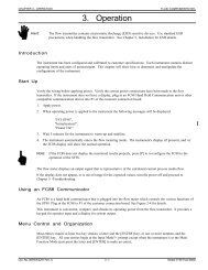
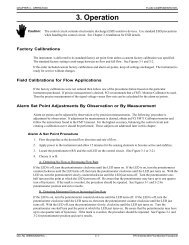
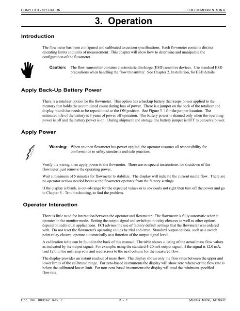
CHAPTER 3 - OPERATION3. <strong>Operation</strong>FLUID COMPONENTS INTLIntroductionThe flowmeter has been configured and calibrated to custom specifications. Each flowmeter contains distinctoperating limits and units of measurement. This chapter will show how to determine and manipulate theconfiguration of the flowmeter.Caution:The flow transmitter contains electrostatic discharge (ESD) sensitive devices. Use standard ESDprecautions when handling the flow transmitter. See <strong>Chapter</strong> 2, Installation, for ESD details.Apply Back-Up Battery PowerThere is a totalizer option for the flowmeter. This option has a backup battery that keeps power applied to thememory that holds the accumulated count during loss of power. There is a jumper on the back of the totalizer anddisplay board that needs to be repositioned to the ON position. See Figure 3-1 for the jumper location. Theestimated life of the battery is 3 years of power off operation. The battery power is drained only when the operatingpower is off and the battery power is on. During shipment and storage, the battery jumper is OFF to conserve power.Apply PowerWarning:When an open flowmeter has power applied, the operator assumes all responsibility forconformance to safety standards and safe practices.Verify the wiring, then apply power to the flowmeter. There are no special instructions for shutdown of theflowmeter; just remove the operating power.Wait a minimum of 5 minutes for flowmeter to stabilize. The display will indicate the current media flow. There areno operator actions needed because the flowmeter operates from the factory settings.If the display is blank, is out-of-range for the expected values or is obviously not right then turn off the power and goto <strong>Chapter</strong> 5 - Troubleshooting, to find the problem.Operator InteractionThere is little need for interaction between the operator and flowmeter. The flowmeter is fully automatic when itoperates in the monitor mode. Setting the output signal and switch point relay closures as well as other optionsdepend on individual applications. FCI advises the use of factory default settings that the flowmeter was orderedwith. Do not reset the flowmeter's operating values by trial and error. Standard output options, such as a switchpoint relay closure, operate automatically as a function of the output signal level.A calibration table can be found in the back of this manual. The table shows a listing of the actual mass flow valuesas indicated by the output signal. For example: using the standard 4-20 mA output signal, if the signal is 12.0 mA,find 12.0 in the milliamp row and read across to the next column for the measured flow.The display provides an instant readout of mass flow. The display shows only the flow rates between the upper andlower limits of the calibrated range. For zero-based instruments the display will show zero whenever the flow rate isbelow the calibrated lower limit. For non-zero-based instruments the display will read the minimum specifiedflow rate.Doc. No. 003162 Rev. F 3 - 1 Models MT86, MT86HT
FLUID COMPONENTS INTLCHAPTER 3 - OPERATIONThe flow totalizer accumulates the total quantity of media that has passed the flow element over a specific time.Short two connector terminals together on the display board to reset the flow totalizer display, see Figure 3-1 fordetails. In applications where the operator is required to reset zero, FCI recommends that these terminals be broughtout to a convenient reset switch.Figure 3-1. Battery Jumper and Reset LocationsNon-Zero Based CalibrationThis is a factory preset item.In a non-zero based calibration, the low-limit output signal (4 mA) is equal to the minimum calibrated flow. Theminimum calibrated flow is a value greater than zero. The flowmeter's output signal will indicate the low-limit flowsignal (4 mA) from zero flow up to the low-flow limit parameter. Use a non-zero based calibration when theminimum flow rate does not approach zero and the turndown ratios are small.At no-flow, the minimum customer specified flow rate will appear on the display.Models MT86, MT86HT 3 - 2 Doc. No. 003162 Rev. F
CHAPTER 3 - OPERATIONFLUID COMPONENTS INTLZero Based CalibrationIn a zero based calibration, the slope of the output signal is shifted so the low-limit flow output signal (4 mA) isequal to zero flow. See Figure 3-2 for details. Flowmeters cannot measure zero flow accurately. The flowmeter willreadout the low-limit signal (4 mA) from zero flow up to the minimum calibrated flow. Then the output signal willstep up to the proper signal value of the mass flow.Figure 3-2. Zero Based CalibrationThe output signal is easier to interpolate when milliamp output is interfaced with control room 0 to 100% gauges;50% of the signal will correspond to 50% of the maximum flow rate.Zero based flowmeters have less signal to resolve over full scale. A zero based flowmeter with a turndown ratio of10:1 will have 10% less output range to resolve flow (5.6 mA to 20 mA instead of 4 mA to 20 mA in a non-zerobased flowmeter).Delta "R" TableThe actual data chart for this particular flowmeter can be found in the page protector at the back of this manual. TheDelta "R" part of this sheet gives the factory calibration measurement points of the Delta "R" differences between theREF and ACT RTDs at certain flow rates. These measurements used by the factory determine the linearizationcoefficients that are applied over the desired flow range. The corresponding current and voltage output readings arealso shown for the factory default settings.The flow versus Delta "R" relationship is fixed for a given set of sensing points. There is a lookup table that is in thepage protector in the back of this manual. It is a printout of factory default settings for zero and offset readings. Thetable shows the relationship between the displayed mass flow readings as they are related to the current output. Theoutput is calculated over the entire flow range with the use of a fitting equation and its respective coefficients.The Delta "R" Table has a great deal of useful information. The table can be used to verify the correct operation ofthe flow transmitter without the flow elements connected. By using the Delta "R" Table the flow element sensingpoints are simulated with precision resistors or decade boxes.Doc. No. 003162 Rev. F 3 - 3 Models MT86, MT86HT
FLUID COMPONENTS INTLGenerating New Delta "R" TablesCHAPTER 3 - OPERATIONUsing the FC81 Calibrator1. Obtain the correct FC81 Field Calibrator for the MT86 or MT86HT Flowmeter:Model FC81-8 is used for the MT86 with 1000 ohm flow element sensing point RTDs.Model FC81-7 is used for the MT86HT with 100 ohm flow element sensing point RTDs.2. Turn the operating power OFF and then disconnect the flow element cable from the terminal block TS1 on theinput board.3. Connect the FC81 Field Calibrator cable to terminal block TS1 (sensing point 1). Also, connect the cable to oneof the output module connectors P7, P8, P9, or P11 that is located on the control board. A set of precisiondecade boxes can be used instead of the FC81 Field Calibrator. Use the wiring diagram in Figure 5-4 to connectthe decade boxes.4. On the control board, monitor the voltage (VDC) across TP10 (-) and TP9 (+) and from TP5 (-) to J8 (+).5. On the output board, monitor the output signal (4 to 20 mA, 10 to 50 mA, 0 to 5 VDC, etc.,) with a DMM.6. Close switch SW1-3 that puts the flow transmitter in the manual mode; this enables the head-select switch SW2to select and monitor one sensing point.7. Set the head-select switch SW2 to the number one (1) position.8. Verify that switch SW4 is in the OP (OPerate) position.9. Turn the operating power ON and let the system stabilize for a minimum of 5 minutes.10. Set the FC81 Field Calibrator to the "READ VOLTS" position and remove the "ADD OHMS" by setting bothbuttons to the OUT position. The voltage on the FC81 Field Calibrator can now be read. This is the samevoltage that is across TP5 (-) and J8 (+). Adjust the voltages by turning the "OHMS ADJUST" potentiometer.11. On a blank Delta "R" sheet, write down the serial number of the flowmeter and the flow element serial number.Blank Delta "R" sheets are obtained from FCI Customer Service.12. Adjust the "OHMS ADJUST" potentiometer to give an output of 4.00 mA, which is zero volts on the FC81Field Calibrator.13. On the Delta "R" sheet record the TP9 to TP10 voltage, the TP5 to J8 voltage (which is the same voltage thatthe FC81 Field Calibrator displays), the MILLIAMP OUTPUT and the LOCAL DISPLAY reading, ifapplicable.14. Depress the "SET OHMS" button on the FC81 Field Calibrator to display the new Delta "R" value for the4.00 mA output. With the FC81 Field Calibrator "SET OHMS" Button depressed the flowmeter does not readthe Delta "R" values. The DMMs will give open circuit or random values.15. Record the new Delta "R" on the data sheet. For Model FC81-8 Field Calibrator the displayed Delta "R" valueis divided by 10 . For Model FC81-7 there is no division necessary.16. Set the calibrator to "READ VOLTS" and then adjust the "OHMS ADJUST" potentiometer to give thefollowing outputs: 5.00, 6.00, 8.00, 12.00, 16.00, and 20.00 mA and repeat Steps 13 through 16 for each.17. Turn the operating power OFF. Then transfer the FC81 Field Calibrator cable to terminal block TS2.18. Turn the operating power ON. Allow one minute for the flowmeter to stabilize.19. Set the calibrator to "Read Volts" and repeat Steps 10 through 16. Remember to set the head-select switch,SW2, to the number 2 position for sensing point number 2.20. Repeat this procedure for all the remaining sensing points in the system. Remember to set the head-select switchSW2 to the sensing point number that a new Delta "R" table is generated for.21. When the Delta "R" table has been completed for the whole system, set the head-select switch to the totalnumber of sensing points in the system. For example, a flowmeter that has 4 sensing points should have thehead-select switch SW2 in position 4.22. Open switch SW1-3, which places the flow transmitter in the automatic mode. This puts the flowmeter back intothe operation mode.Models MT86, MT86HT 3 - 4 Doc. No. 003162 Rev. F
FLUID COMPONENTS INTLCHAPTER 3 - OPERATIONTable 3-1. Jumper Configuration For Output AdjustmentMODEFactory Set Span andZeroSpan Only AdjustActivatedINSTALL JUMPERJ1 J2 J3* J4* J5 J6 J7 J8YES NO YES NO YES NO YES NONO YES YES NO YES NO NO YESSpan and Zero Activation NO YES YES NO NO YES NO YES* J3 and J4 will always be in this position unless the factory has authorized option changes.1. Repeat steps 1 through 5 from above. Record the Delta "R" that was required to generate the milliamp outputfor both the low and high flow rates.2. Remove jumpers J1, J5 and J7. Add jumpers J2, J6 and J8, to make the span and zero circuitry active.3. Adjust the FC81 Field Calibrator, or precision decade boxes, to the Delta "R" resistance that represents the lowflow milliamp output of Step 1.4. Adjust the zero potentiometer, R17, on the control board to give the milliamp output that represents thecalculated low flow.5. Adjust the FC81 Field Calibrator, or precision decade boxes, to the Delta "R" resistance value that representsthe high flow milliamp output from Step 1.6. Repeat Steps 3 through 5 until the correct milliamp output matches the Delta "R" for the high and low flows.7. Disconnect the FC81 Field Calibrator or precision decade boxes and reconnect the sensing point to its originalinput board.8. Return switch SW1-3 to the open position.9. Set the head-selector, SW2, to the number of sensing points in the system. The flowmeter can be reset to thefactory set calibration with the use of the original jumper setup. The originally installed jumpers are J1, J3, J5and J7. The above span and zero adjustments are not in effect when the flowmeter is in the originalconfiguration. The factory set calibrations are in control of the flowmeter. Table 3-1 shows the jumper settingsthat are needed to make the zero and span adjustments active. Figure 3-3 shows the zero and span effects on theflowmeter.If only the zero adjust needs to be done, the span and zero jumpers will need to be set. Then proceed with the zeroadjustment.Figure 3-3. Zero and Span AdjustmentModels MT86, MT86HT 3 - 6 Doc. No. 003162 Rev. F
CHAPTER 3 - OPERATIONFLUID COMPONENTS INTLIf a span and zero adjustment can not be done, the other choice for adjustment is an EPROM replacement. TheEPROM stores the data that represents the calibrated flow rate and the performance curve. FCI can provide a newEPROM with the new data and/or range. The customer does have to provide FCI with Analog-to-Digital (A/D)information and the flow rate so the EPROM can be made. Look at the Delta "R" table to get the A/D number. Inthe Delta "R" table, one column is categorized as Voltage In Non-Linear, [TP9 (+) to TP10 (-)].Use the following equation to calculate the A/D number for the Non-Temperature Compensated flowmeter only.Write down the results in the chart shown in Figure 3-4.A/D = ( [TP9 - TP10 (Vdc)]/2 ) X 5( 4096 )For the Temperature Compensated flowmeter, the A/D equation is:A/D = [( [TP9 - TP10 (Vdc)]/2 ) X (4096)]/(TC Gain)TC Gain is a function of the reference temperature. Additional data for the TC Gain is needed. This data is the REFSEN (+) to GND SEN (-) voltage from terminal block TS#.Note:This A/D versus flow information is needed for each flow element sensing point in the flowmeter.FCI strongly recommends that as much data as possible be gathered because the calibration will be only as good asthe data supplied. Once a new EPROM is provided it will need to be installed (see the Repair procedure in<strong>Chapter</strong> 5) and a new Delta "R" table generated (see the preceding section for the procedure).Doc. No. 003162 Rev. F 3 - 7 Models MT86, MT86HT
FLUID COMPONENTS INTLCHAPTER 3 - OPERATIONA/D DATA SHEETSERIAL NUMBER_______________SERVICE ____________________ _FLOW RATE/LOAD _____________OUTPUT (mA) _________________ (TOTAL OUTPUT)DATE_______________UNIT________________COMPANY___________SENSORPOINTSDIS mA TP9-10 R. VDC* A/D**12345678SENSORPOINTSDIS mA TP9-10 R. VDC* A/D**12345678* R. VDC is the reference voltage measured at the individual connectors from points numbered 2(-) to number 3 (+).** A/D will be calculated at FCI with the above information.Close dip switch 3 at SW1 (for manual operation) then dial the head selector, SW2, to the desired flow element.Figure 3-4. A/D Data SheetModels MT86, MT86HT 3 - 8 Doc. No. 003162 Rev. F