FlexCOR Model CMF Series - Fluid Components International
FlexCOR Model CMF Series - Fluid Components International
FlexCOR Model CMF Series - Fluid Components International

Create successful ePaper yourself
Turn your PDF publications into a flip-book with our unique Google optimized e-Paper software.
TM<br />
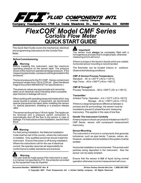
<strong>FlexCOR</strong> <strong>Model</strong> <strong>CMF</strong> <strong>Series</strong><br />
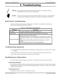
This Quick Start Guide covers the mechanical, electrical<br />
and programming instructions for the Coriolis Flow<br />
Meter.<br />
Before Commissioning<br />
Warning<br />
Before installing this instrument, read the maximum<br />
operating pressure on the sensor label. The pressure<br />
shown is the maximum operational design pressure. If the<br />
measuring pipe breaks, a pressure will be generated in the<br />
enclosure.<br />
The burst pressure for the FCI <strong>CMF</strong> - <strong>Series</strong> containment<br />
enclosure ranges from 700 to 2700 psi. (See Handbook<br />
Page 6 Document 06EN003327 for specifications.)<br />
The pressure values are approximate and cannot be<br />
taken as an absolute value indicating when a possible<br />
pipe fracture or leakage will occur.<br />
When working with operating pressures/media which may<br />
cause injuries to people, or equipment, we recommend<br />
special precautions be taken when installing the sensor<br />
i.e. special placement, shielding or a pressure release<br />
valve.<br />
The sensor enclosure has a 1/8 inch nipple. The nipple can<br />
be removed and a pressure switch connected to<br />
automatically shut off the flow to the sensor in case of<br />
leakage. For instructions on the installation, see the Hand<br />
Book.<br />
Coriolis Flow Meter<br />
QUICK START GUIDE<br />
Important!<br />
The sensor must always be completely filled with a<br />
homogeneous process fluid in single phase, otherwise<br />
measuring errors will occur.<br />
If there is air/gas in the liquid or liquids which are volatile,<br />
horizontal sensor mounting is recommended.<br />
The flowmeter can be located indoors or outdoors.<br />
Observe the following conditions:<br />
<strong>CMF</strong>-A Version Process Temperature:<br />
Standard: 40 to +257°F [-40 to +125C]<br />
High Temp.:40 to +356°F [-40 to +180C]<br />
<strong>CMF</strong>-B Through F:<br />
Process Temperature: 58 to +356°F [-50 to +180C]<br />
Transmitter:<br />
Ambient Temp. Operation: -4 to +122°F [-20 to +50C]<br />
Storage: -40 to +158°F [-40 to +70°C]<br />
If there is a large temperature difference between a<br />
process and its surroundings, the sensor must be<br />
insulated to prevent 2-phase flow and measuring<br />
inaccuracy. This applies in the case of low flow.<br />
Handle The Instrument Carefully<br />
A heavy impact or shock can produce imbalance in the FCI<br />
<strong>CMF</strong> <strong>Series</strong> sensor, with consequent measurement<br />
inaccuracy.<br />
Warning<br />
For field wiring installation, the National Installation<br />
Code shall be met of the country, where the instrument<br />
is installed. Only qualified personnel should install this<br />
instrument. Ensure that power is off during installation.<br />
Where the instructions call for the use of electrical<br />
current, the operator assumes all responsibility for<br />
conformance to safety standards and practices.<br />
Warning<br />
The user shall be made aware if the instrument is used<br />
in a manner not specified by FCI, the protection provided<br />
by the equipment may be impaired.<br />
Sensor Mounting<br />
The instrument is immune to components that generate<br />
turbulence, such as pipe bends, T-pieces, valves, etc.<br />
However, cavitation and air bubbles in the system must be<br />
avoided.<br />
Horizontal installation is recommended. This avoids solid<br />
particles being deposited in the instrument. Also the<br />
sensor can be easily emptied.<br />
Ensure that the sensor is full of liquid during normal<br />
operation otherwise incorrect measurement will occur.<br />
Document Number: 06EN003318 Rev. B 24 hour Factory Service Hot Line: 1 (800) 854-1993<br />
© Copyright 2001 <strong>Fluid</strong> <strong>Components</strong> Intl a limited liability company All Rights Reserved
FLUID COMPONENTS, INTL<br />
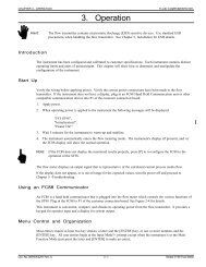
SENSOR IDENTIFICATION<br />
<strong>CMF</strong>-A<br />
Transmitter,<br />
Hazardous Location,<br />
Integral Mount<br />
Transmitter,<br />
Weather Proof,<br />
Integral Mount<br />
Remote Mount<br />
Configuration<br />
<strong>CMF</strong>-B Through F<br />
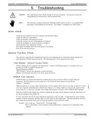
<strong>CMF</strong>-A SENSOR INSTALLATION<br />
Sensor<br />
Ground<br />
(Ex-applications)<br />
Plug<br />
Nipple<br />
Media Output (Preferred)<br />
Process Connection<br />
The mounting bracket supplied with the <strong>CMF</strong>-A<br />
instrument must always be used. The unit must be<br />
mounted on a wall or steel frame (vibration-free).<br />
The plug is used as an indicator for the mounting<br />
position of the sensor. The plug should always be<br />
placed within 5° top center of vertical.<br />
Bracket<br />
Support<br />
Media Input (Preferred)<br />
Process connections<br />
<strong>CMF</strong>-A Mounting Bracket and Position<br />
Sensor<br />
Plug<br />
Nipple<br />
Ground<br />
(Ex-applications)<br />
Bracket<br />
Support<br />
Process connections<br />
The mounting brackets supplied with the <strong>CMF</strong>-A instrument must always be used. The unit must be mounted on a wall or<br />
steel frame (vibration-free).<br />
<strong>CMF</strong>-A Plug Orientation<br />
Plug<br />
Plug<br />
Plug<br />
To obtain the optimum performance, the plug should be mounted as shown. The plug can be turned within the angles stated.<br />
Horizontal <strong>CMF</strong>-A Mounting in Pipe for Liquid or Gas<br />
Horizontal mounting<br />
Liquid applications<br />
Horizontal mounting is recommended in low flow liquid so that air bubbles<br />
are easier to remove.<br />
Horizontal mounting<br />
Gas applications<br />
For liquid applications, locate the sensor low in the pipe system in order to<br />
avoid under-pressure in the sensor and consequent air separation in the<br />
liquid. Due to the capillary tube effect, the sensor is not self emptying.<br />
<strong>FlexCOR</strong> TM <strong>Model</strong> <strong>CMF</strong> <strong>Series</strong> Coriolis Flow Meter 2 Doc. No. 06EN003318 Rev. B
FLUID COMPONENTS, INTL<br />
Direction of Horizontal Flow<br />
Horizontal sensor mounting is recommended for air/gas processes.<br />
Forward<br />
Valve<br />
Reverse<br />
Valve<br />
A shut-off valve should be installed to facilitate the zero-point adjustment of<br />
the sensor. To avoid elimination of the air form the process, a back pressure<br />
of a minimum of 15. to 3 psi is recommended.<br />
The arrow on the sensor indicates the direction of positive flow (the meter is<br />
able to measure flow in both directions).<br />
The liquid should flow in the direction of the arrow (on the sensor) to avoid<br />
partial emptying of the sensor, especially with low flow.<br />
Static back pressure / min. 0.1 bar (1.5 psi)<br />
There should be a check or solenoid valve that closes when the flow is zero<br />
so that the liquid does not flow back and causes partial emptying of the sensor.<br />
Vertical Mounting in Pipe<br />
Vertical mounting<br />
Gas applications<br />
Reverse<br />
The <strong>CMF</strong>-A is most efficient for gas applications when it is mounted as shown. The<br />
<strong>CMF</strong>-A is most efficient for liquid applications when it is mounted as shown.<br />
The <strong>CMF</strong>-A can measure flow in both directions.<br />
Forward<br />
Vertical mounting<br />
Liquid applications<br />
Vertical Mounting Plug Orientation<br />
Plug<br />
With vertical mounting the orientation of the terminal box is not important, rotation,<br />
however, is not allowed to exceed the stated angles of the sensor.<br />
Mounting of the Pressure Switch<br />
Ground<br />
(Ex-applications)<br />
Plug<br />
Nipple<br />
Important<br />
Read the following information before removing the nipple from the sensor<br />
enclosure.<br />
Avoid getting humidity, liquid or particles into the sensor. It may damage the<br />
meter. Following this procedure is recommended.<br />
1. Leave the sensor in a dry and clean place to acclimate until it obtains<br />
ambient temperature, best at approximately 70°F (20 C).<br />
2. Be careful when removing the nipple and mounting the pressure switch.<br />
3. Check the pressure switch has been correctly mounted and tightened so<br />
the sealing ring fits tightly. Always replace old sealing rings with new ones<br />
after each disassembly.<br />
Connecting the Pipe<br />
Plug<br />
Important<br />
When connecting/disconnecting the pipe, the cable has to be mechanically<br />
connected in order to prevent liquid from penetrating into the sensor. The<br />
sensor is only IP 65 (dust and splash proof) when the plug is mounted.<br />
Doc. No. 06EN003318 Rev. B 3 <strong>FlexCOR</strong> TM <strong>Model</strong> <strong>CMF</strong> <strong>Series</strong> Coriolis Flow Meter
FLUID COMPONENTS, INTL<br />
Vibration<br />
Locate the instrument as far away as possible from components that generate<br />
mechanical vibration in the piping.<br />
Cross-Talk<br />
If the instruments are located close to each other, e.g. in the same pipe section,<br />
the instruments may interfere with each other's measurements, especially with<br />
low flow applications. Install a flexible connection between instruments,<br />
instead of a hard pipe connection.<br />
Avoid mounting the instrument on the same steel frame. I.e. insulate the meters<br />
mechanically.<br />
<strong>CMF</strong>- B Through F SENSOR INSTALLATION<br />
Mounting the <strong>CMF</strong>-B through F sensors are very similar to mounting the <strong>CMF</strong>-A. A pictorial account of mounting will be given.<br />
Horizontal Mounting in Pipe<br />
Direction of Flow<br />
Direction of<br />
Vertical Flow<br />
Vertical Mounting in Pipe<br />
Horizontal mounting<br />
for Liquid applications<br />
Forward<br />
Valve<br />
Ok for gas<br />
or liquid<br />
applications<br />
Horizontal mounting<br />
for Gas applications<br />
Not for Liquid applications<br />
Reverse<br />
Valve<br />
Static back pressure min. 0.1 bar<br />
Valve<br />
Direction of flow<br />
Static back<br />
pressure min.<br />
0.1-0.2 bar<br />
Ok for gas<br />
applications<br />
Only<br />
Vibration<br />
Locate the flowmeter as far away as possible from<br />
components that generate mechanical vibration in the<br />
piping.<br />
Ensure that there is no direct connection with them e.g.<br />
by using flexible connections. The flowmeter can be<br />
located after a bend.<br />
<strong>FlexCOR</strong> TM <strong>Model</strong> <strong>CMF</strong> <strong>Series</strong> Coriolis Flow Meter 4 Doc. No. 06EN003318 Rev. B
FLUID COMPONENTS, INTL<br />
Cross-Talk<br />
Mounting of Pressure Release Valve<br />
Nipple<br />
Nipple<br />
ELECTRICAL CONNECTIONS<br />
<strong>CMF</strong> <strong>Series</strong> Plug Connection<br />
<strong>CMF</strong> - A PLUG CONNECTION<br />
Mount the plug in the receptacle and tighten<br />
the knurled back shell on the plug to obtain a<br />
good seal.<br />
<strong>CMF</strong> - B Through F PLUG CONNECTION<br />
Plug<br />
Note the wire colors when connecting the<br />
<strong>CMF</strong>-B through F. Refer to the diagram for<br />
electrical wiring.<br />
Wiring the Transmitter<br />
Separate the enclosure from the base. Route<br />
conduit and cables to the instrument. Connect<br />
the instrument per the following diagrams.<br />
Screw (2) Places Screw (2) Places<br />
Loosen Allen<br />
screw, unscrew<br />
back cover<br />
Unscrew Front<br />
Face<br />
Doc. No. 06EN003318 Rev. B 5 <strong>FlexCOR</strong> TM <strong>Model</strong> <strong>CMF</strong> <strong>Series</strong> Coriolis Flow Meter
FLUID COMPONENTS, INTL<br />
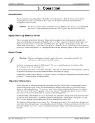
Wiring the Cable Between the Transmitter and the Sensor (Remote Transmitter Configuration)<br />
Mount the plug in the sensor and connect the wire colors as shown in the diagram to the transmitter.<br />
1<br />
2<br />
3<br />
4<br />
BROW N<br />
RED<br />
ORANGE<br />
YELLOW<br />
81<br />
82<br />
0<br />
83<br />
<strong>CMF</strong>-A<br />
<strong>CMF</strong>-B Through F<br />
9<br />
8<br />
7<br />
6<br />
5<br />
SENSOR<br />
PLUG<br />
(FACTORY WIRED)<br />
84<br />
0<br />
BLACK<br />
90<br />
WHITE<br />
89<br />
GREY<br />
88<br />
VIOLET<br />
87<br />
0<br />
TRANSMITTER<br />
BLUE<br />
86<br />
GREEN<br />
85<br />
TRANSMITTER<br />
MOTHER BOARD<br />
(CUSTOMER WIRED)<br />
Power Input and Signal Output Wiring Diagrams<br />
Note: All connections are made on the<br />
terminal blocks of the base enclosure<br />
mother board.<br />
<strong>FlexCOR</strong> TM <strong>Model</strong> <strong>CMF</strong> <strong>Series</strong> Coriolis Flow Meter 6 Doc. No. 06EN003318 Rev. B
FLUID COMPONENTS, INTL<br />
Prom Insertion into a Wall Instrument The remote mounted transmitter requires the<br />
installation of a SENSORPROM.<br />
Open the transmitter as shown previously.<br />
Remove the mother board by unscrewing a<br />
captive screw found in the center of the board.<br />
Pull up on the board.<br />
Press the SENSORPROM onto the metal pronged<br />
structure inside the enclosure. The SENSORPROM<br />
label must face the closest enclosure wall.<br />
Press the mother board on top of the<br />
SENSORPROM and tighten the captive screw.<br />
Close the transmitter.<br />
Wall of<br />
Enclosure<br />
SENSORPROM<br />
Metal Prongs<br />
Prom Insertion into a IP66 Mount Instrument<br />
Open the transmitter as shown previously.<br />
Install the SENSORPROM as shown, with the label facing the installer.<br />
Close the transmitter.<br />
Zero-Point Adjustment for <strong>CMF</strong>-A Through F<br />
Zeroing the instrument is normally not required in the field. However, if necessary the <strong>FlexCOR</strong> features an auto-zero setting.<br />
Refer to Page 25 and 62 of the handbook document 06EN003327 for instructions on resetting the zero point in the field.<br />
TRANSMITTER MENU MANIPULATION<br />
Keypad and Display Layout<br />
The keypad is used to set the flowmeter. The function of the keys are as follows:<br />
TOP UP KEY<br />
FORWARD KEY<br />
BACKWARD KEY<br />
CHANGE KEY<br />
SELECT KEY<br />
LOCK/UNLOCK KEY<br />
This key (hold 2 sec.) switches between operator<br />
menu and setup menu. When In the converter<br />
setup menu, a short press will cause a return to<br />
the previous menu.<br />
This key steps forward through the menus. It is<br />
the only key normally used by the operator.<br />
This key is steps backward through the menus.<br />
This key changes settings or numerical values.<br />
This key selects the numerals to be changed.<br />
This key allows the operator to change settings<br />
and accesses submenus.<br />
The display is alphanumeric and indicates flow values, flowmeter settings and error messages.<br />
The upper line is for primary flow readings and will always show either mass flow rate, volume flow rate, density,<br />
temperature, totalizer 1 or totalizer 2. The line is divided into 3 fields.<br />
S: Sign field<br />
P: Primary field for numerical value<br />
U: Unit field<br />
The center line is the title line (T) with individual information according to the selected operator or setup menu.<br />
Doc. No. 06EN003318 Rev. B 7 <strong>FlexCOR</strong> TM <strong>Model</strong> <strong>CMF</strong> <strong>Series</strong> Coriolis Flow Meter
FLUID COMPONENTS, INTL<br />
The lowest line is the subtitle line (ST) which either will add information to the title line or keep individual information independent<br />
of the title line.<br />
F: The alarm field. Two flashing triangles will appear by a fault condition.<br />
M: The mode field. The symbols indicate the following.<br />
Communication mode Product identity Output Reset mode<br />
Service mode Language mode External input<br />
Operator menu Basic settings Sensor characteristic<br />
L: The lock field. Indicates the function of the lock key.<br />
Ready for change<br />
Value locked<br />
Access to submenu<br />
RESET MODE: Zero setting of totalizers and initialization of setting<br />
Menu Modes<br />
The menu is built up in two parts. An operator menu and a setup menu.<br />
Operator menu<br />
The operator menu is for daily operation. The operator menu is customized in the operator menu setup. The transmitter always<br />
starts in the operator menu no. 1. The page forward and page backward keys are used to step through the operator menus.<br />
Setup menu<br />
The setup menu is for commissioning and service only.<br />
Access to the setup menu is gained by pressing the top up key for 2 seconds. The setup menu will operate in two modes:<br />
View mode Setup mode<br />
View mode is a read only mode. The pre-selected settings can only be scanned.<br />
Setup mode is a read and write mode. The pre-selected settings can be scanned and changed. Access to the setup mode is<br />
protected with a password. The factory set password is 1000.<br />
Access to a submenu in the set up menu is gained by the lock key. A short press on the top up key will go back to the previous<br />
menu. A long press (2 sec.) on the top up key will exit the setup menu and bring to operator menu no. 1.<br />
Password<br />
The SETUP MENU can be operated in two different modes: VIEW MODE (Read only) and CHANGE MODE (Read and write<br />
mode)<br />
To access to view mode, press the forward key when in the password menu.<br />
<strong>FlexCOR</strong> TM <strong>Model</strong> <strong>CMF</strong> <strong>Series</strong> Coriolis Flow Meter 8 Doc. No. 06EN003318 Rev. B
FLUID COMPONENTS, INTL<br />
IMPORTANT: Access to the change mode is protected by a user code. The user code is factory set to 1000, but can<br />
be changed to any value between 1000 and 9999 in the change password menu.<br />
The factory setting of 1000 can be reestablished by switching off power . Then press the TOP UP key while switching<br />
on the power. The user code is now reset to 1000.<br />
Example of Programming of Max Mass Flow and Event Changes<br />
Basic settings menu description:<br />
This menu is used for basic configuration of the instrument with a choice of units, minimum and maximum limits for display<br />
and analog/digital outputs for all measurement parameters, i.e. mass flow, volume flow, fraction, temperature and density.<br />
Settings of min./max. values and units:<br />
Numerical values are entered by placing the cursor in the field that is to be set using the SELECT key. Press unlock and the<br />
value can be changed using the change key. The desired value is locked by activating LOCK.<br />
Positioning of the decimal point is carried out by placing the cursor below the decimal point using the SELECT key. The position<br />
can be set using the set key. The LOCK key is activated and the decimal point is now positioned.<br />
Selecting the unit:<br />
Place the cursor below the unit using SELECT key. Set the desired unit using CHANGE key. Press the LOCK key to save the<br />
setting. Place the cursor below the time scale using SELECT key . Choose the desired time scale using CHANGE. Save the<br />
value by pressing the LOCK key.<br />
The maximum and minimum values set will then apply to all outputs, e.g. where the min. value will correspond to 0-4 mA<br />
depending on the setting of the current output and the max. will correspond to 20 mA.<br />
As example, to change the default setting of the maximum mass flow on a <strong>CMF</strong>-A from 20 Kg/h to .45 lb/min, do the following:<br />
Keypad operation Implementation Display on Transmitter<br />
Push for 2 sec. To access the Password<br />
user password 0000<br />
Push once To unlock password CHANGE<br />
0000<br />
Push once To enter 1000 as CHANGE<br />
password 1000<br />
Push once To lock password and to CONV.SETUP MODE><br />
enter the menu<br />
Basic settings<br />
Push once To enter basic setting Flow direction<br />
submenu<br />
Positive<br />
Push once To go to mass flow Massflow max.<br />
max. setting<br />
000020. kg/h<br />
Push once To change num. Massflow max.<br />
value<br />
000020. kg/h<br />
Push 4 times To move the cursor Massflow max.<br />
to the num. position<br />
000020. kg/h<br />
Push Until 4 appears Massflow max.<br />
000040. kg/h<br />
Push once To move the cursor to Massflow max.<br />
the next num. position<br />
000040. kg/h<br />
Push Till 5 appears Massflow max.<br />
000045. kg/h<br />
Push once To move the cursor to Massflow max.<br />
the decimal point<br />
000045. kg/h<br />
Push To position the decimal Massflow max.<br />
point correct<br />
0000.45 kg/h<br />
Push 3 times To move cursor Massflow max.<br />
to "Kg" unit<br />
0000.45 kg/h<br />
Push twice To change units to lb. Massflow max.<br />
0000.45Lb/h<br />
Push once To move cursor to Massflow max.<br />
the "h" unit<br />
0000.45Lb/h<br />
Push 3 times To change "h" to "min" Massflow max.<br />
0000.45 Lb/min<br />
Push To lock the new setting Massflow max.<br />
of the mass flowmeter<br />
000.45 Lb/m<br />
Push twice<br />
Transmitter reverts to<br />
standard operation<br />
MENU CMDS<br />
Doc. No. 06EN003318 Rev. B 9 <strong>FlexCOR</strong> TM <strong>Model</strong> <strong>CMF</strong> <strong>Series</strong> Coriolis Flow Meter
FLUID COMPONENTS, INTL<br />
Programming Relay Output<br />
The output functions error level, error number and direction/limit can also be implemented on the relay output. Programming<br />
of the relay output is identical to the digital output.<br />
Programming Current Output<br />
The current output should be set off when not used, otherwise an error will be pending if the meter detects an open loop.<br />
<strong>FlexCOR</strong> TM <strong>Model</strong> <strong>CMF</strong> <strong>Series</strong> Coriolis Flow Meter 10 Doc. No. 06EN003318 Rev. B
FLUID COMPONENTS, INTL<br />
Menu Tree<br />
Doc. No. 06EN003318 Rev. B 11 <strong>FlexCOR</strong> TM <strong>Model</strong> <strong>CMF</strong> <strong>Series</strong> Coriolis Flow Meter
FLUID COMPONENTS, INTL<br />
ERROR<br />
CODES<br />
Error Error text #Comment Outputs Input<br />
No. Remedy text status status<br />
1 I1 - Power on<br />
OK Power on has activated. Active Active<br />
2 I2 - Add-on Module<br />
Applied A new module has been added to the system. Active Active<br />
3 I3 - Add-on Module An add-on module is bad or has been removed.<br />
Install This can also be an internal add-on module. Active Active<br />
4 I4 - Param. corrected A less vital parameter in the converter has been<br />
OK replaced by its default value. Active Active<br />
20 W20 - Totalizer 1 During initialization, the check of the saved totalize<br />
Reset manually<br />
value failed. The saved totalizer value is not reliable.<br />
Reset the totalizer value manually to rely on readings. Active Active<br />
20 W20 - Totalizer 2 During initialization, the check of the saved totalize<br />
Reset manually<br />
value failed. The saved totalizer value is not reliable.<br />
Reset the totalizer value manually to rely on readings. Active Active<br />
21 W21 - Pulse overflow Actual flow is too big compared with pulse width and Reduced<br />
Adjust pulse settings mass/pulse. pulse width Active<br />
22 W22 - Batch timeout Duration of batching has exceeded a predefined Batch out-<br />
Check installation maximum time. put on zero Active<br />
23 W23 - Batch overrun Batch quantity has exceeded a predefined maximum Batch out-<br />
Check installation overrun mass or volume. put on zero Active<br />
24 W24 - Batch neg. flow<br />
Check flow direction Negative flow direction during batch. Active Active<br />
30 W30 - Flowsaturated<br />
Adjust max. flow Flow is above Q max. settings. Max. 120 % Active<br />
31 W31- Empty pipe Pipe is empty. Zero Active<br />
32 W32 - Temp. to high The temperature of the fluid has exceeded the max.<br />
Adjust temperature temperature rating of the sensor (180 C). Active Active<br />
33 W33 - Temp. to low The temperature of the fluid has exceeded the min.<br />
Adjust temperature temperature rating of the sensor (-50 C). Active Active<br />
34 W34 - Zero Adj. fail Zero-point values are out of limits because of flow in the<br />
Check flow = zero sensor. Check zero flow conditions, valves, pumps etc. Active Active<br />
35 W35 - Current Out 1 Current output exceeds 120%. Ensure that the sensor is<br />
Check max. settings correctly sized and check maximum flow setting. Active Active<br />
36 W36 - Freq/Pulse Out1 Freq/Pulse output exceeds 120%. Ensure that the sensor<br />
Check max. settings is correctly sized and check maximum flow setting. Active Active<br />
40 P40 - SENSORPROM <br />
Insert SENSORPROM unit not installed. Active Active<br />
41 P41 - Parameter range A parameter is out of range.<br />
Switch off and on The error will disappear at the next power-on. Active Active<br />
42 P42 - Current output Current loop is disconnected or the loop resistance<br />
Check cables is too big. Active Active<br />
43 P43 - Internal error Internal error.<br />
Switch off and on Active Active<br />
49 P49 - Protec. viol. Too many errors occured at the same time.<br />
Switch off and on Some errors are not detected correctly. Active Active<br />
50 P50 - Temp. cable Error in temperature sensor, check cables and<br />
Check cable connectors. Active Active<br />
51 P51 - Pick-up 1 Pick-up 1 amplitude too low. Check cables or application<br />
Check cable/install. for damping (air/gas in liquid). Active Active<br />
52 P52 - Pick-up 2 Pick-up 2 amplitude too low. Check cables or application<br />
Check cable/install. for damping (air/gas in liquid). Active Active<br />
60 F60 - CAN comm. error CAN bus communication error. An add-on module, the<br />
Converter/add-on module display module or the converter is defect Zero Inactive<br />
61 F61 - SENSORPROM err. SENSORPROM data is not reliable.<br />
Replace Active Active<br />
62 F62 - SENSORPROM ID SENSORPROM unit ID doesn't match instrument ID.<br />
Replace The SENSORPROM unit is from another instrument. Zero Inactive<br />
63 F63 - SENSORPROM It is not possible to read from the SENSORPROM <br />
Replace unit . Active Active<br />
70 F70 - Pick-up phase Check cables/polarity. Active Active<br />
71 F71 - Driver phase Check cables/polarity. Active Active<br />
80-83 F80, 81, 82, 83 - Internal error Restart or replace. Active Active<br />
84 F84 - Sensor level Pick-up amplitude saturated. Active Active<br />
97 F97 - Add-on module to old Replace. Active Active<br />
Error code level: W = Warning F = Fatal P = Permanent<br />
Notice of Proprietary Rights<br />
This document contains confidential technical data, including trade secrets and proprietary information which are the property of <strong>Fluid</strong><br />
<strong>Components</strong> Intl (FCI). Disclosure of this data to you is expressly conditioned upon your assent that its use is limited to use within your company<br />
only (and does not include manufacture or processing uses). Any other use is strictly prohibited without the prior written consent of FCI.<br />
Visit FCI on the Worldwide Web: www.fluidcomponents.com<br />
<strong>FlexCOR</strong> TM <strong>Model</strong> <strong>CMF</strong> <strong>Series</strong> Coriolis Flow Meter 12 Doc. No. 06EN003318 Rev. B