

MGL EFIS data feed documentation - MGL Avionics
MGL EFIS data feed documentation - MGL Avionics
MGL EFIS data feed documentation - MGL Avionics

Create successful ePaper yourself
Turn your PDF publications into a flip-book with our unique Google optimized e-Paper software.
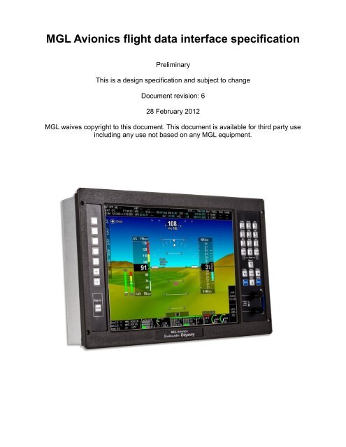
<strong>MGL</strong> <strong>Avionics</strong> flight <strong>data</strong> interface specification<br />
Preliminary<br />
This is a design specification and subject to change<br />
Document revision: 6<br />
28 February 2012<br />
<strong>MGL</strong> waives copyright to this document. This document is available for third party use<br />
including any use not based on any <strong>MGL</strong> equipment.
General<br />
This document describes the raw <strong>data</strong> format used for transferring flight <strong>data</strong> information from<br />
an <strong>EFIS</strong> system to an <strong>MGL</strong> avionics flight <strong>data</strong> recording device (black box flight recorder) or<br />
other devices.<br />
The following message IDs are defined:<br />
Message 01 – Primary flight <strong>data</strong><br />
Message 02 – GPS <strong>data</strong><br />
Message 03 – Attitude <strong>data</strong><br />
Message 04 – Various inputs (flaps, gear, etc)<br />
Message 05 – Traffic file<br />
Message 06 – Alert/Warning/Information text message<br />
Message 10 – Engine message<br />
Message 11 – Fuel tank levels<br />
Message 30 – Navigation <strong>data</strong> (Active navigation information, HSI, VSI, GSI)<br />
Message 31 – Secondary navigation <strong>data</strong><br />
Message 35 - COM<br />
Message 41 – Flight plan header<br />
Message 42 – Flight plan item<br />
Message 200-255 – Vendor specific. Please obtain information from your vendor.<br />
Data is transmitted over standard RS232 signaling using the TX line. RX line is not used by<br />
transmitting equipment.<br />
Baudrate is set to 115200 at 8 bits per character, 1 start and 1 stop bit.<br />
This allows transmission of up to 11520 bytes per second.<br />
Message <strong>data</strong> is binary and arranged to suit processors that have word boundary access<br />
limitations (such as most ARM implementations). Messages are arranged to favor DMA<br />
message pipes common in modern micro controllers to allow message reception without<br />
microprocessor core involvement (Direct UART -> Memory transfers).<br />
Receiving equipment must be able to handle a message length of up to 276 bytes total (up to<br />
264 bytes <strong>data</strong>).<br />
Messages can be securely received by means of a strong message start synchronization<br />
(05+02+Message length+Message length xor 0xFF). This prevents false synchronization on<br />
message content. Data content can be verified using a standard CRC 32 bit checksum giving<br />
a high level of <strong>data</strong> integrity confidence.<br />
A message length of 0x00 should be interpreted as 0x100, I.e. 256 bytes.<br />
Each message contains a byte that shows its average message rate per second. A further<br />
byte shows the message number within that second. This can be used at the receiving side to<br />
detect missing messages. This number counts up from 1 and is reset to 1 at the start of the<br />
next system second. For message rates of 1 per second, this byte alternates between 0 and 1<br />
for every transmission.<br />
It is acceptable for the <strong>EFIS</strong> to vary the rate per message on a per second bases. For
example, one second it may send 10 messages of a particular type, the next second it may<br />
decide to send 5 messages. However, the <strong>EFIS</strong> MUST update the message rate information<br />
byte in the message. Message rate changes MUST only occur when the message counter is<br />
at its reset value (at start of the current second).<br />
For flight <strong>data</strong> recording purposes, the <strong>data</strong> recorder may skip messages that exceed the set<br />
recording rate. For example, a message may be transmitted 10 times per second but the flight<br />
<strong>data</strong> recorder elects to only record one message per second.<br />
Note: Message count is assumed to be asynchronous and would be reset to 1 at the start of a<br />
system second. It is permissible for the transmitting device to skip messages where this is<br />
needed for bandwidth control or it may be due to system load reasons. Due to the typical<br />
asynchronous nature of these transmissions with respect to time it is also possible for a<br />
message count to exceed the message rate number. For example, a message with a rate of 4<br />
per second may have a message count field of 5 before being reset to 1 for the next second.<br />
Devices should not use message count fields or message arrival times for internal timing as<br />
these are not guaranteed.<br />
Data types<br />
Longint<br />
Smallint<br />
Word<br />
Byte<br />
String<br />
Byte order<br />
32 bit signed integer<br />
16 bit signed integer<br />
16 bit unsigned integer<br />
8 bit unsigned integer<br />
Byte based string of characters. The first byte is length of string and any<br />
characters in ASCII follow. Unused locations are to be treated as<br />
“don't care”. An empty string has a “0” in the first location.<br />
Example: String[6] – This string can have up to 6 characters and it<br />
occupies 7 bytes (length byte plus six characters).<br />
This is different to a “C” string but has the advantage that any value can<br />
be used as a character so this method can be used to store flexible length<br />
general <strong>data</strong>.<br />
Data types consisting of more than one byte are sent LSB first and MSB last<br />
Unknown or invalid values<br />
Any unknown or invalid quantity in a message should be set to zero unless otherwise<br />
mentioned in the specification of the message.<br />
Message length byte in header<br />
The message length byte refers to length of <strong>data</strong> portion (excluding header, checksum plus 8<br />
bytes default message length).
The <strong>data</strong> portion of a message MUST be at least 9 bytes in size. This is the case for all<br />
standard messages. If the <strong>data</strong> portion is 9 bytes in size, the length byte has a value of “1”<br />
and the XOR byte following has a value of 0xFE (0x01 xor 0xFF).<br />
This scheme allows the transmission of a 256 byte <strong>data</strong> page with a private 8 byte header.<br />
Total, maximum number of bytes in a message is thus: 276 bytes<br />
8 bytes header (starting at DLE)<br />
+<br />
9 to 264 bytes of <strong>data</strong> (maximum 256+8 bytes private header)<br />
4 bytes checksum<br />
If you parse a packet of <strong>data</strong> and you have just received the XOR'ed version of the length<br />
byte and thus can verify the length, you need to receive a further “length byte” + 16 bytes to<br />
receive all outstanding bytes in the packet including the 4 byte checksum.<br />
Checksum location<br />
Checksum location must be on a 4 byte boundary, counting from the DLE - filler bytes are<br />
inserted if needed to ensure this. This is to allow even 32 bit word access to the checksum in<br />
a receiver using an ARM processor or similar with word size boundary access restrictions or<br />
to utilize CRC32 hardware available in some processor chips that may be restricted to using<br />
word (32 bit) aligned <strong>data</strong>.
Message 01: Primary flight<br />
This message should be sent by the <strong>EFIS</strong> at a recommended rate of 5 per second. Rates<br />
from 1 to 30 per second are acceptable based on the systems requirements.<br />
DLE: byte; 0x05<br />
STX: byte; 0x02<br />
MessageLength: byte; 0x18 36 bytes following MessageVersion - 12<br />
MessageLengthXOR: byte; 0xE7<br />
MessageType: byte; 0x01<br />
MessageRate: byte; 0x05<br />
MessageCount: byte; Message Count within current second<br />
MessageVersion: byte; 0x01<br />
PAltitude: longint; Pressure altitude in feet<br />
BAltitude: longint; Pressure altitude in feet, baro corrected<br />
ASI: word; Indicated airspeed in 10 th Km/h<br />
TAS: word; True airspeed in 10 th Km/h<br />
AOA: smallint; Angle of attack in tenth of a degree<br />
VSI: smallint; Vertical speed in feet per minute<br />
Baro: word; Barometric pressure in 10 th millibars (actual<br />
measurement from altimeter sensor, actual pressure)<br />
Local: word; Local pressure setting in 10 th millibars (QNH)<br />
OAT: smallint; Outside air temperature in degrees C<br />
Humidity: byte; 0-99%. If not available 0xFF<br />
SystemFlags: Byte; See description below<br />
Hour,Minute,<br />
Second,Date,<br />
Month,Year: bytes; Time as set in RTC. 24 hour format, two digit year.<br />
FTHour,FTMin: bytes; Flight time since take off. Hours, minutes.<br />
Checksum longint; CRC32<br />
SystemFlags:<br />
bit 0 0: no flight active 1: flight active<br />
bit 1 0: no OAT sensor 1: OAT sensor detected<br />
bit 2 0: no humidity sensor 1: Humidity sensor detected
Message 02: GPS Message<br />
This message contains basic GPS information. This message should be sent at a rate<br />
compatible with the systems GPS update rate (typically from 1 to 10 per second). Minimum<br />
rate is 1 per second.<br />
DLE: byte; 0x05<br />
STX: byte; 0x02<br />
MessageLength: byte; 0x24 48 bytes following MessageVersion - 12<br />
MessageLengthXOR: byte; 0xDB<br />
MessageType: byte; 0x02<br />
MessageRate: byte; 0x04<br />
MessageCount: byte; Message Count within current second<br />
MessageVersion: byte; 0x01<br />
Latitude: longint; Latitude in degrees / 180.000 (+ = North)<br />
Longitude: longint; Longitude in degrees / 180.000 (+ = East)<br />
GPSAltitude: longint; Altitude from GPS in feet<br />
AGL: longint; Altitude above ground level as determined by terrain<br />
North velocity: longint; velocity towards north cm/s<br />
East velocity: longint; velocity towards east cm/s<br />
Down velocity: longint; velocity towards down cm/s<br />
GroundSpeed: word; Ground speed from GPS in 10 th Km/h<br />
TrackTrue: word; True track from GPS. 10 th of a degree<br />
Variation: smallint; Magnetic variation in 10 th of a degree. Negative is west.<br />
GPS byte; See description below<br />
SatsTracked: byte; Number of satellites tracked<br />
SatsVisible: byte; Total number of satellites visible<br />
HorizontalAccuracy: byte; Horizontal GPS accuracy estimate in feet<br />
VerticalAccuracy: byte; Vertical GPS accuracy estimate in feet<br />
GPS capability: byte; See below<br />
RAIM status: byte; See Raim information below<br />
RAIM HError: byte; Horizontal expected error<br />
RAIM VError: byte; Vertical expected error<br />
PaddingByte1: byte; 0x00 For alignment<br />
Checksum longint; CRC32<br />
GPS byte<br />
This byte shows the GPS mode:<br />
0 : Acquiring<br />
1: GPS internal dead reckoning<br />
2: 2D fix<br />
3: 3D fix<br />
4: 2D fix <strong>EFIS</strong> dead reckoning (IMU)<br />
5: 3D fix <strong>EFIS</strong> dead reckoning (IMU)
RAIM information<br />
Status: 0: no satellite fail detected, else ID of most likely failed satellite<br />
HError,VError: Horizontal and Vertical error in feet, based on using only satellites that<br />
passed the RAIM test.<br />
Note: GPS <strong>data</strong> items are validated against this value. All GPS derived values are invalid if<br />
GPS byte is 0. GPS altitude is invalid if GPS byte is not 3 or 5.<br />
The <strong>EFIS</strong> system may use dead reckoning to arrive at a higher position update rate than the<br />
GPS system can provide, for example using IMU. If the current <strong>data</strong> is based on a dead<br />
reckoning estimate, the GPS mode is 4 or 5.<br />
GPS capability<br />
Bit 0: 0: GPS not designed to DO-229 1: GPS designed to DO-229 Beta 1 or higher<br />
Bit 1: 0: Not WAAS capable or disabled 1: WAAS capable and enabled<br />
Bit 2: 0: No RAIM functionality 1: RAIM functional and enabled<br />
Bit 3: 0: GPS can track less than 12 sats 1: GPS can track more than 11 sats<br />
Bit 4: 0: GPS cannot use Glonast/Galileo 1: GPS can use Glonast/Galileo
Message 03: Attitude<br />
This message is sent typically at the processed AHRS rate, not the native AHRS rate.<br />
Transmission rates are typically related to <strong>EFIS</strong> screen refresh or internal image drawing<br />
update rates. Typical rates are from 1 to 50 messages per second. Recommended rates<br />
would be from 10 to 25 to ensure smooth image creation where this is needed.<br />
DLE: byte; 0x05<br />
STX: byte; 0x02<br />
MessageLength: byte; 0x14 32 bytes following MessageVersion - 12<br />
MessageLengthXOR: byte; 0xEB<br />
MessageType: byte; 0x03<br />
MessageRate: byte; 0x0A<br />
MessageCount: byte; Message Count within current second<br />
MessageVersion: byte; 0x01<br />
HeadingMag: word; Magnetic heading from compass. 10 th of a degree<br />
PitchAngle: smallint; AHRS pitch angle 10 th of a degree<br />
BankAngle: smallint; AHRS bank angle 10 th of a degree<br />
YawAngle: smallint; AHRS yaw angle 10 th of a degree (see notes below)<br />
TurnRate: smallint; Turn rate in 10 th of a degree per second<br />
Slip: smallint; Slip (ball position) -50 (left) to +50 (right)<br />
GForce: smallint; Acceleration acting on aircraft in Z axis (+ is down)<br />
LRForce: smallint; Acceleration acting on aircraft in left/right axis (+ if right)<br />
FRForce: smallint; Acceleration acting on aircraft in forward/rear axis (+ is<br />
forward)<br />
BankRate: smallint; Rate of bank angle change (See notes on units)<br />
PitchRate: smallint; Rate of pitch angle change<br />
YawRate: smallint; Rate of yaw angle change<br />
SensorFlags: byte; See description below<br />
PaddingByte1: byte; 0x00 For alignment<br />
PaddingByte2: byte; 0x00 For alignment<br />
PaddingByte3: byte; 0x00 For alignment<br />
Checksum longint; CRC32<br />
SensorFlags:<br />
bit 0 0: No magnetic compass 1: Magnetic compass detected<br />
bit 1 0: No AHRS 1: AHRS detected<br />
bit 2 0: No GPS 1: GPS detected and operational<br />
bit 3 0: No meaning 1: AHRS over range or compromised<br />
bit 4 0: AHRS is gyro 1: AHRS does not use gyros (GPS derived)<br />
bit 5 0: No X/Y acceleration 1: X/Y acceleration is measured<br />
bit 6 0: No rates 1: Rates are provided<br />
Accelerations<br />
Accelerations are in 100 th of a G.
Yaw Angle<br />
Yaw angle is system specific. It may be referenced to North (true or magnetic) or it can be<br />
freely drifting, depending on the underlying hardware implementation.<br />
Gyro Rates<br />
Rates are transmitted in a 16 bit signed format involving two scaling factors chosen<br />
depending on the rate at the time.<br />
For sensor rates less than 150 degrees per second:<br />
Value is in 100 th of a degree per second. Highest value is thus +14999 or -14999<br />
For sensor rates higher or equal to 150 degrees per second:<br />
Value is in 10 th of a degree per second +/- 1500 +/-15000 depending on direction.<br />
Examples:<br />
Rate is 89.45 degrees per second: Value is 8945.<br />
Rate is 345.3 degrees per second: Value is 16953. (3453-1500+15000).<br />
Positive numbers: Bank right, Pitch up, Yaw right.<br />
Negative numbers: Bank left, Pitch down, Yaw left.<br />
Euler angle ranges<br />
Bank Angle range: -1800 to +1799 – positive is bank right<br />
Pitch Angle range: -900 to +899 – positive is pitch up<br />
Yaw Angle range: 0 to 3599
Message 04: Various input states and signals<br />
This message is sent typically at a rate of 2 per second. It contains readings related to analog<br />
and digital inputs that can be populated as needed by a vendor.<br />
DLE: byte; 0x05<br />
STX: byte; 0x02<br />
MessageLength: byte; Depends on message content<br />
MessageLengthXOR: byte; Depends on message content<br />
MessageType: byte; 0x04<br />
MessageRate: byte; 0x02<br />
MessageCount: byte; Message Count within current second<br />
MessageVersion: byte; 0x01<br />
NumberOfAnalogInputs: byte; Number of analog input reading in this message<br />
NumberOfDigitalInputs: byte; Number of digital input readings in this message<br />
Gear 1 state: byte;<br />
Gear 2 state: byte;<br />
Gear 3 state: byte;<br />
Gear 4 state: byte;<br />
Gear 5 state: byte;<br />
FlapPosition: byte;<br />
FlapPositionAnalog: smallint;<br />
PitchTrimPosition: smallint;<br />
BankTrimPosition: smallint;<br />
YawTrimPosition: smallint;<br />
Digital:<br />
longint; //Up to 32 bits for digital input states<br />
Analog:<br />
array[0..NumberOfAnalogInputs-1] of word; //See notes<br />
Checksum longint; CRC32<br />
The number of analog inputs must be even (0 is allowed). This is to ensure long word (4 byte)<br />
alignment of checksum.<br />
Gear states are up to the vendor to define. They can be used for anything and are not<br />
necessarily used for “landing gear”.<br />
For landing gear the states are typical:<br />
0 Gear down<br />
1-254 Gear in intermediate position (can be a scaled value of actual position if known)<br />
255 Gear up<br />
Analog values are 16 bit, usually raw ADC values but may be scaled to present quantities etc.<br />
For <strong>MGL</strong> systems the values are scaled based on settings on the <strong>EFIS</strong>.<br />
Flap positions are:<br />
0 Unknown<br />
1 Flap up<br />
2 Flap 1<br />
3 Flap 2<br />
4 Flap down<br />
10 Flap up, negative (some aircraft allow negative flap positions for fast cruise)<br />
Flap position analog – as decided by vendor<br />
Trim positions – as decided by vendor. It is recommended to use 0 as “neutral”
Message 05: Traffic file<br />
This message is sent at a rate of once per second. It contains up to 32 traffic items.<br />
Traffic items may be sorted in threat order if the system supports this (this is identified by the<br />
traffic mode bit).<br />
Traffic location is processed by the <strong>EFIS</strong> regardless of source and shown in latitude and<br />
longitude if possible. Range or Bearing only messages can also be included.<br />
DLE: byte; 0x05<br />
STX: byte; 0x02<br />
MessageLength: byte; Depends on number of traffic items<br />
MessageLengthXOR: byte; Depends on number of traffic items<br />
MessageType: byte; 0x06<br />
MessageRate: byte; 0x01<br />
MessageCount: byte; 0 or 1, alternating with every transmission<br />
MessageVersion: byte; 0x01<br />
Traffic mode: byte; See description below<br />
Number of traffic: byte; Number of traffic in this transmission (0 to 32)<br />
Number of messages: byte; Number of messages (1,2,3 or 4)<br />
Message number: byte; Number of this message (starts with “1” or zero if none).<br />
Followed by:<br />
0 to 7 messages of a traffic item (32 bytes each)<br />
Latitude: longint; in degrees / 180000 or Range in meters<br />
Longitude: longint; in degrees / 180000 or Bearing in 10 th degree<br />
Altitude: longint; in feet. 0X80000000 if not known<br />
Track: smallint; in 10 th degrees. -1 if not known<br />
Speed: smallint; in Km/h. -1 if not known<br />
Vertical Speed: longint; in feet/minute. Positive is climbing.<br />
Callsign: string[6] Callsign. 0X00 in first location if not known<br />
Source: byte; Source of traffic information, see below<br />
Threat level: byte; See below. 0 if not known<br />
Resolution: byte; See below. 0 if no resolution system<br />
Aircraft category: byte; See below. 0 if not known<br />
Traffic ID: byte; Number of traffic message in total transmission<br />
If no traffic is available, message length is set to 1 and a blank <strong>data</strong> portion with 9 bytes of<br />
value 0x00 is sent.<br />
Traffic mode:<br />
0 – Traffic items are unsorted<br />
1 -- Traffic items are sorted by distance<br />
2 – Traffic items are sorted by threat level<br />
Traffic source:<br />
0 - Unknown<br />
1 - TCAS or TIS (ARINC 429 or other <strong>data</strong> <strong>feed</strong>)<br />
2 - PCAS<br />
3 - FLARM
4 - ADS-B<br />
5 - ADS-B 1090 ES<br />
6 - Unspecified source giving at least lat/long of traffic location<br />
7 - Unspecified source giving range only<br />
8 - Unspecified source giving bearing only<br />
Threat level<br />
0 – Unknown<br />
1 – None<br />
2 – Mild<br />
3 – High<br />
4 – Danger<br />
Resolution<br />
0 – Unknown<br />
Bit 0 set – pull up<br />
Bit 1 set – push down<br />
Bit 2 set – bank right<br />
Bit 3 set – bank left<br />
Bit 4 set – speed up<br />
Bit 5 set – slow down<br />
Bit 6 set – Add “sharp” to resolution<br />
Bit 7 set – Threat resolution available, do nothing<br />
Aircraft category<br />
Aircraft categories are based on DO-260B and defined as follows:<br />
0 - No defined category, emitter set “A”<br />
1 - Light<br />
2 - Small<br />
3 - Large<br />
4 - High vortex large<br />
5 - Heavy<br />
6 - High performance<br />
7 - Rotor craft<br />
8 - No defined category, emitter set “B”<br />
9 - Glider<br />
10 - Lighter than air<br />
11 - Parachutist<br />
12 - Ultralight<br />
13 - Reserved<br />
14 - UAV<br />
15 - Space<br />
16 - No defined category, emitter set “C”<br />
17 - Surface, emergency vehicle<br />
18 - Surface, service vehicle<br />
19 - Point obstacle<br />
20 - Line obstacle
21..23 - Undefiend<br />
24 - No defined category, emitter set “D”<br />
25..31 Undefined<br />
255 - This traffic item does not have any category identification
Message 10: Engine <strong>data</strong><br />
This message is sent at a rate typically from 1 to 10 times per second depending on<br />
implementation. Each engine has one message.<br />
DLE: byte; 0x05<br />
STX: byte; 0x02<br />
MessageLength: byte; Depends on message content<br />
MessageLengthXOR: byte; Depends on message content<br />
MessageType: byte; 0x0A<br />
MessageRate: byte; As required<br />
MessageCount: byte; As required<br />
MessageVersion: byte; 0x01<br />
Engine number: byte; 1..Number of engines<br />
Engine type: byte; 0 – Piston 1 – Turbine<br />
For Combustion engines:<br />
Number of EGT: byte;<br />
Number of CHT: byte;<br />
RPM: word; Revolutions / minute<br />
PULSE: word; AUX pulse/RPM value<br />
OIL pressure 1: word; In 10 th of a millibar (Main oil pressure)<br />
OIL pressure 2: word; In 10 th of a millibar (optional second oil pressure)<br />
Fuel pressure: word; In 10 th of a millibar<br />
Coolant temperature: smallint; In degrees C<br />
OIL temperature 1: smallint; In degrees C<br />
OIL temperature 2: smallint; In degrees C<br />
AUX temperature 1: smallint; In degrees C<br />
AUX temperature 2: smallint; In degrees C<br />
AUX temperature 3: smallint; In degrees C<br />
AUX temperature 4: smallint; In degrees C<br />
Fuel flow: word; In 10 th liters/hour<br />
AUX flow: word; In 10 th liters/hour<br />
Manifold pressure: word; In 10 th of a millibar<br />
Boost pressure: word; In 10 th of a millibar<br />
Inlet temperature: smallint; In degrees C<br />
Ambient pressure: word; In 10 th of a millibar (intake air pressure)<br />
EGT: smallint; In degrees C - Repeated for each EGT<br />
CHT: smallint; In degrees C – Repeated for each CHT<br />
For turbine engines:<br />
Inlet temperature: smallint; In degrees C<br />
N1 longint; RPM<br />
N2 longint; RPM<br />
Exhaust temperature: smallint; In degrees C<br />
OIL pressure 1: word; In 10 th of a millibar (Main oil pressure)
OIL pressure 2: word; In 10 th of a millibar (optional second oil pressure)<br />
Fuel pressure: word; In 10 th of a millibar<br />
OIL temperature 1: smallint; In degrees C<br />
OIL temperature 2: smallint; In degrees C<br />
AUX temperature 1: smallint; In degrees C<br />
AUX temperature 2: smallint; In degrees C<br />
AUX temperature 3: smallint; In degrees C<br />
Fuel flow: word; In 10 th liters/hour<br />
Ambient pressure: word; In 10 th of a millibar (intake air pressure)<br />
Padding: word; Set to zero. Used to align checksum.<br />
Either engine type is followed by:<br />
Checksum longint; CRC32
Message 11: Fuel levels<br />
This message is sent at a rate of 1 times per second.<br />
DLE: byte; 0x05<br />
STX: byte; 0x02<br />
MessageLength: byte; Depends on message content<br />
MessageLengthXOR: byte; Depends on message content<br />
MessageType: byte; 0x0B<br />
MessageRate: byte; 1<br />
MessageCount: byte; 0 – 1 alternating<br />
MessageVersion: byte; 0x01<br />
Number of tanks: longint; Longint used for alignment purposes<br />
For each tank:<br />
Level: longint; In 10 th liters<br />
Tank type: byte; See below<br />
Tank on: byte; See below<br />
Tank sensors: word; See below<br />
Followed by:<br />
Checksum longint; CRC32<br />
Tank type:<br />
0: physical tank with a level sender<br />
1: virtual tank, level is calculated from fuel flow and starting value<br />
2: virtual tank, level is calculated from flight time and starting value<br />
Other values may be used as required by implementer<br />
Tank on:<br />
0: Tank is off<br />
1: Tank is on<br />
2: Unknown<br />
Tank sensors:<br />
This item can be used by implementer as needed. It is recommended to use value 0xFFFF if<br />
this item is not used.
Message 30: Navigation<br />
This message is sent typically at a rate of 1 per second.<br />
DLE: byte; 0x05<br />
STX: byte; 0x02<br />
MessageLength: byte; 0x2C ;56 bytes – 12 following MessageVersion<br />
MessageLengthXOR: byte; 0xD3<br />
MessageType: byte; 0x04<br />
MessageRate: byte; 0x02<br />
MessageCount: byte; Message Count within current second<br />
MessageVersion: byte; 0x01<br />
Flags: word; NAV validity flags, see below<br />
HSISource:<br />
byte;<br />
VNAVSource: byte;<br />
APMode: byte; 0 = not engaged, 1 = engaged<br />
Padding:<br />
byte;<br />
HSINeedleAngle: smallint; Relative HSI needle angle +1800 to -1800. 0 = up<br />
HSIRoseHeading: word; 0-3599<br />
HSIDeviation: smallint; -4096 to 4095 for full deflection<br />
VerticalDeviation: smallint; -4096 to 4095 for full deflection<br />
HeadingBug: smallint; 0-3599<br />
AltimeterBug: longint; in feet<br />
WPDistance: longint;<br />
WPLatitude: longint; <strong>MGL</strong> format, 180000 per degree<br />
WPLongitude: longint; <strong>MGL</strong> format, 180000 per degree<br />
WPTrack: smallint; 0-3599<br />
VOR1Radial: smallint; 0-3599<br />
VOR2Radial: smallint; 0-3599<br />
DME1: word; in 0.1 Km steps<br />
DME2: word; in 0.1 Km steps<br />
ILSDeviation: smallint; -4096 to 4095 for full deflection<br />
GSDeviation: smallint; -4096 to 4095 for full deflection<br />
GLSHorizontalDeviation: smallint; -4096 to 4095 for full deflection<br />
GLSVerticalDeviation: smallint; -4096 to 4095 for full deflection<br />
Padding:<br />
word;<br />
Checksum longint; CRC32<br />
Flag bits are:<br />
0 HSI valid<br />
1 VNAV valid<br />
2 Waypoint valid<br />
3 Autopilot engaged<br />
4 VOR1 valid<br />
5 VOR2 valid<br />
6 DME1 valid<br />
7 DME2 valid<br />
8 ILS valid
9 GS valid<br />
10 GLS valid<br />
All angular values are in 10 th of a degree. Deviations range from -4096 to +4095 for full needle<br />
deflection.<br />
HSI Nav source<br />
0 Vectors (heading bug)<br />
1 GPS waypoint navigation<br />
2 VOR navigation<br />
3 ILS<br />
VNAV source<br />
0 Altitude bug<br />
1 Glide slope<br />
AP Mode is split into 2 nibbles of 4 bits. The lower 4 bits shows vertical mode, the upper 4 bits<br />
shows horizontal mode.<br />
Horizontal mode:<br />
0 Heading bug<br />
1 HSI<br />
Vertical mode:<br />
0 Set Altimeter bug to current altitude, then follow Altimeter bug<br />
1 Altimeter bug<br />
2 Vertical speed hold<br />
3 Flight plan vertical NAV<br />
4 Pitch attitude hold<br />
5 Vertical mode suspended, use only horizontal NAV<br />
6 Air speed hold
Checksum calculation<br />
Checksum calculation is done from the first byte following MessageLengthXOR to the last<br />
<strong>data</strong> byte before the checksum. Here is a sample source in C which uses fast table lookup<br />
CRC calculation. The table can be calculated on startup or can be pre-calculated and stored<br />
in ROM.<br />
Header File<br />
// CRCdemo.h<br />
protected:<br />
ULONG crc32_table[256]; // Lookup table array<br />
void Init_CRC32_Table(); // Builds lookup table array<br />
ULONG Reflect(ULONG ref, char ch); // Reflects CRC bits in the<br />
lookup table<br />
int Get_CRC(CString& text); // Creates a CRC from a text string<br />
Source File<br />
// CRCdemo.cpp<br />
void CRCdemo::Init_CRC32_Table()<br />
{// Call this function only once to initialize the CRC table.<br />
// This is the official polynomial used by CRC-32<br />
// in PKZip, WinZip and Ethernet.<br />
ULONG ulPolynomial = 0x04c11db7;<br />
// 256 values representing ASCII character codes.<br />
for(int i = 0; i
}<br />
// bit 1 for bit 6, etc.<br />
for(int i = 1; i < (ch + 1); i++)<br />
{<br />
if(ref & 1)<br />
value |= 1 >= 1;<br />
}<br />
return value;<br />
int CRCdemo::Get_CRC(CString& text)<br />
{ // Pass a text string to this function and it will return the CRC.<br />
// Once the lookup table has been filled in by the two functions above,<br />
// this function creates all CRCs using only the lookup table.<br />
// Note that CString is an MFC class.<br />
// If you don't have MFC, use the function below instead.<br />
// Be sure to use unsigned variables,<br />
// because negative values introduce high bits<br />
// where zero bits are required.<br />
// Start out with all bits set high.<br />
ULONG ulCRC(0xffffffff);<br />
int len;<br />
unsigned char* buffer;<br />
}<br />
// Get the length.<br />
len = text.GetLength();<br />
// Save the text in the buffer.<br />
buffer = (unsigned char*)(LPCTSTR)text;<br />
// Perform the algorithm on each character<br />
// in the string, using the lookup table values.<br />
while(len--)<br />
ulCRC = (ulCRC >> 8) ^ crc32_table[(ulCRC & 0xFF) ^ *buffer++];<br />
// Exclusive OR the result with the beginning value.<br />
return ulCRC ^ 0xffffffff;
Revision history<br />
1 - Internal release<br />
2 - Internal release<br />
3 - Changed spec for length byte in header to accommodate 256 byte <strong>data</strong> pages with<br />
private 8 byte header. Added Traffic file (message 06).<br />
4 - Added message 10 (Engine <strong>data</strong>), Message 11 (Fuel level)<br />
5 - Internal release<br />
6 - Redefined message 04 as “various inputs”, Changed message 06 to message 05.<br />
Dropped autopilot message (<strong>data</strong> now included in Navigation message). Defined message 04<br />
and message 30. Clarified length byte.


