

MGL EFIS data feed documentation - MGL Avionics
MGL EFIS data feed documentation - MGL Avionics
MGL EFIS data feed documentation - MGL Avionics

You also want an ePaper? Increase the reach of your titles
YUMPU automatically turns print PDFs into web optimized ePapers that Google loves.
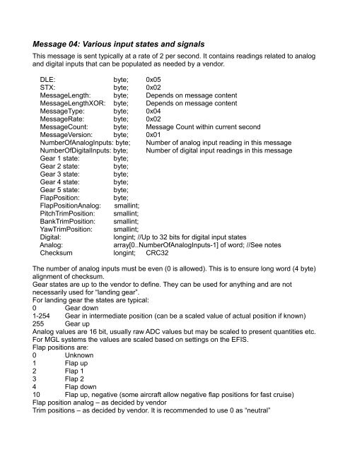
Message 04: Various input states and signals<br />
This message is sent typically at a rate of 2 per second. It contains readings related to analog<br />
and digital inputs that can be populated as needed by a vendor.<br />
DLE: byte; 0x05<br />
STX: byte; 0x02<br />
MessageLength: byte; Depends on message content<br />
MessageLengthXOR: byte; Depends on message content<br />
MessageType: byte; 0x04<br />
MessageRate: byte; 0x02<br />
MessageCount: byte; Message Count within current second<br />
MessageVersion: byte; 0x01<br />
NumberOfAnalogInputs: byte; Number of analog input reading in this message<br />
NumberOfDigitalInputs: byte; Number of digital input readings in this message<br />
Gear 1 state: byte;<br />
Gear 2 state: byte;<br />
Gear 3 state: byte;<br />
Gear 4 state: byte;<br />
Gear 5 state: byte;<br />
FlapPosition: byte;<br />
FlapPositionAnalog: smallint;<br />
PitchTrimPosition: smallint;<br />
BankTrimPosition: smallint;<br />
YawTrimPosition: smallint;<br />
Digital:<br />
longint; //Up to 32 bits for digital input states<br />
Analog:<br />
array[0..NumberOfAnalogInputs-1] of word; //See notes<br />
Checksum longint; CRC32<br />
The number of analog inputs must be even (0 is allowed). This is to ensure long word (4 byte)<br />
alignment of checksum.<br />
Gear states are up to the vendor to define. They can be used for anything and are not<br />
necessarily used for “landing gear”.<br />
For landing gear the states are typical:<br />
0 Gear down<br />
1-254 Gear in intermediate position (can be a scaled value of actual position if known)<br />
255 Gear up<br />
Analog values are 16 bit, usually raw ADC values but may be scaled to present quantities etc.<br />
For <strong>MGL</strong> systems the values are scaled based on settings on the <strong>EFIS</strong>.<br />
Flap positions are:<br />
0 Unknown<br />
1 Flap up<br />
2 Flap 1<br />
3 Flap 2<br />
4 Flap down<br />
10 Flap up, negative (some aircraft allow negative flap positions for fast cruise)<br />
Flap position analog – as decided by vendor<br />
Trim positions – as decided by vendor. It is recommended to use 0 as “neutral”


