Kalzip® Systems
Kalzip® Systems
Kalzip® Systems

Create successful ePaper yourself
Turn your PDF publications into a flip-book with our unique Google optimized e-Paper software.
Kalzip ® <strong>Systems</strong><br />
Product information and specification
Content<br />
Page<br />
1.Kalzip aluminium roof and façade systems 4<br />
2. Kalzip innovations 5<br />
3. The system and its components<br />
3.1 Dimensions of the profiled sheets 6<br />
3.2 Aluminium clip and thermal barrier pads 7<br />
3.3 Different finishes and colours 10<br />
3.4 Accessories 12<br />
3.5 Components for roof superstructures and safety appliances 14<br />
4. Kalzip range of applications<br />
Non-ventilated Kalzip roof on a trapezoidal steel deck 16<br />
Non-ventilated Kalzip roof on purlins with trapezoidal inner sheet 17<br />
Non-ventilated Kalzip roof on timber rafters with visible timber lining 17<br />
Kalzip DuoPlus ® 100 and Kalzip Duo ® 100 on a concrete substructure 18<br />
Kalzip DuoPlus 100 18<br />
Kalzip Duo 100 18<br />
Kalzip NatureRoof ® 19<br />
Kalzip FOAMGLAS ® System as a standard and combined solution 19<br />
Kalzip AF 20<br />
Kalzip AF with ProDach-insulation on trapezoidal steel deck 20<br />
Kalzip AF with ProDach-insulation on timber rafters with formwork 21<br />
Kalzip AF with the insulation layer at rafter level 21<br />
Kalzip AF on FOAMGLAS ® insulation 21<br />
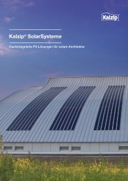
Kalzip Solar Power <strong>Systems</strong> 22<br />
Kalzip AluPlusSolar 22<br />
Kalzip SolarClad 23<br />
5. General data and characteristics<br />
5.1 Roof pitch 24<br />
5.2 Minimum radii for crimp-, smooth- and on site curving 24<br />
5.2.1 Kalzip Convex Factory crimp-curved 24<br />
5.2.2 Kalzip smooth curved in factory, aluminium 25<br />
5.2.3 Kalzip supplied in straight form, curved to radius during installation (naturally curved) 26<br />
5.3 Tapered shapes 27<br />
5.4 Kalzip XT free-form profiled sheets Kalzip type 65 /… / 1.0 mm 28<br />
5.5 Accessibility/fall arrest systems 29<br />
5.6 Material/corrosion resistance 30<br />
5.7 Sustainable construction 31<br />
5.8 Official approvals/design calculations 32<br />
5.9 Transport 32<br />
5.10 Sheet thickness 32
Page<br />
6. Design specifications<br />
6.1 Moisture proof 33<br />
6.2 Ice barriers 33<br />
6.3 Sound absorption 34<br />
6.4 Fire protection 34<br />
6.5 Lightning protection using Kalzip aluminium profiled sheet envelopes 35<br />
6.6 Roof systems 36<br />
6.6.1 Rafter roof: Kalzip sheets perpendicular to the trapezoidal steel deck 36<br />
6.6.2 Kalzip perpendicular on timber lining 37<br />
6.6.3 The purlin roof: Kalzip parallel to inner skin 38<br />
6.6.4 Kalzip DuoPlus 100 and Kalzip Duo 100 39<br />
6.6.5 Kalzip FOAMGLAS ® System 40<br />
6.7 Connections 42<br />
6.8 Thermal expansion 43<br />
6.9 Design of fixed points Kalzip aluminium clip / Kalzip composite clip 43<br />
6.10 Ridge, eaves, gable ends 43<br />
6.11 Skylights/Smoke/heat extractors 44<br />
6.12 Transverse joints 44<br />
6.13 Substructures 45<br />
6.14 Cantilevers/clip bars 45<br />
6.15 Installation rules 45<br />
6.16 Roof projections without clip bars 46<br />
6.17 Installation instructions for long profiled sheets 46<br />
7. Kalzip dimensioning tables<br />
7.1 Thermal conductivity coefficients when using Kalzip composite clips for WLG 040 and WLG 035 47<br />
7.2 Thermal conductivity coefficients for Kalzip DuoPlus 100 roof (WLG 040) 47<br />
7.3 Clip spacings 48<br />
7.3.1 Rafter roof (multi-span sheets) with composite clips 48<br />
7.3.2 Purlin roof (multi-span sheets) with composite clips 49<br />
7.3.3 Kalzip ProDach (adjacent) with aluminium clips 50<br />
7.3.4 Kalzip AluPlusSolar 50<br />
Index 51
Introduction<br />
1. Kalzip aluminium roof and façade systems<br />
Kalzip aluminium building envelopes<br />
have been setting trends worldwide in<br />
contemporary building culture for more<br />
than 40 years.<br />
The almost unlimited variety of forms and<br />
the most diverse intelligent additional<br />
functions continually provide architects<br />
and planners with impetus for sophisticated<br />
architecture<br />
More than 80 million square metres of<br />
installed Kalzip profiled sheets speak<br />
for themselves.<br />
Whether for industrial buildings, exhibition<br />
halls, airports, public amenities such as<br />
sports facilities or the renovation of existing<br />
buildings – the outstanding material characteristics<br />
and flexibility of aluminium allow<br />
an inexhaustible variety of forms and offer<br />
durable secure building protection. As a<br />
leading manufacturer of aluminium profiled<br />
sheets, Kalzip offers with this brochure<br />
comprehensive technical information on<br />
Kalzip aluminium roof and façade systems.<br />
Detailed data on the system provide you<br />
with an in-depth insight into the mode of<br />
functioning of this unique building product.<br />
The economical all-in-one solution<br />
In addition to information on the various<br />
material surfaces, colours and refinements,<br />
you will also find valuable design tips as<br />
well as dimensioning tables to support you<br />
during the planning phase. Technical drawings<br />
and installation examples illustrate<br />
the function of the Kalzip system with com -<br />
ponents and accessories, e.g. clips, on<br />
different roof structures. Additive systems<br />
for new buildings or existing building fabric<br />
are described using examples. The Kalzip<br />
Solar <strong>Systems</strong> offer creative freedom with<br />
maximum efficiency for the integration of<br />
photovoltaic systems.<br />
Karlovy Vary Airport, Czech Republic<br />
Architect: Petr Parolek<br />
4 Kalzip
Innovations<br />
2. Kalzip innovations<br />
This page features our new Kalzip products.<br />
Kalzip XT – for a new architectural era<br />
Kalzip XT profiles enable for the first time<br />
the implementation of computer-generated<br />
forms and design principles. Evolutionary<br />
animations, visualised in 3D objects, give<br />
birth to new architectural-organic forms<br />
– the fusion of biology and architecture.<br />
The advantages in summary:<br />
• Horizontal and vertical profiled sheets in<br />
convex and concave forms are possible<br />
• New variations in the design of<br />
geo me tries thanks to XT free-form<br />
profiled sheets<br />
• Small bending radii guarantee the<br />
roofing of unusual building forms<br />
Further information can be found on page<br />
7 and page 28.<br />
The integrated Kalzip renovation<br />
concept – the durable roof renovation<br />
Emergency repairs to the roofs of old<br />
existing buildings are connected with risks,<br />
since expensive consequential damage<br />
can still occur despite that and the costs<br />
can rise dramatically when ‘permanent<br />
building sites’ are the result. The Kalzip<br />
renovation concept for old roofs takes a<br />
new, sustainable path: the sloping roof<br />
with a roof cladding made of aluminium<br />
profiled sheets and adaptation to the latest<br />
thermal insulation standards.<br />
The advantages of the Kalzip<br />
renovation concept:<br />
• Maximum corrosion resistance due to salt<br />
water-resistant aluminium base material<br />
• Permanent, virtually maintenance-free<br />
building protection<br />
• High creative freedom due to individual<br />
roof forms<br />
• No interruption of use during renovation<br />
• Economical, fast installation<br />
The thermal bridge-optimised composite<br />
clip for Kalzip profiled sheets for the<br />
achievement of EnEV 2009-compliant<br />
roof structures<br />
The Kalzip composite clip consists of a<br />
stable steel core, which is encased by a<br />
glass-fibre reinforced plastic.<br />
Advantages of the product:<br />
• Minimum heat transfer enables a roof<br />
structure that is virtually free of thermal<br />
bridges<br />
• Safe load dissipation into the<br />
substructure<br />
• In order to achieve the desired thermal<br />
insulation thicknesses in EnEV<br />
2009-compliant Kalzip roof structures<br />
and to compensate for height tolerances,<br />
the new Kalzip composite clips can be<br />
combined with spacer pads<br />
Further information can be found on page 8.<br />
Sports arena in Porec (HR)<br />
Gymnasium of the Vallendar comprehensive<br />
school (D) before renovation<br />
Kalzip composite clip<br />
BMW Head Office in Leipzig (D),<br />
winner of the German Architecture Prize 2005.<br />
Architect: Zaha Hadid with Patrik Schumacher<br />
Gymnasium of the Vallendar comprehensive<br />
school (D) after renovation<br />
Architect: Guido Fries Architekten<br />
Kalzip AluPlusSolar installation with composite<br />
clips<br />
Kalzip 5
The system and its components<br />
3. The system and its components<br />
3.1 Dimensions of the profiled sheets<br />
There are many variations in<br />
shape for instance*)<br />
Dimensions mm<br />
Kalzip 50/333<br />
333<br />
50<br />
Thickness mm<br />
1.2<br />
1.0<br />
0.9<br />
0.8<br />
straight<br />
Kalzip 50/429<br />
429<br />
50<br />
1.2<br />
1.0<br />
0.9<br />
0.8<br />
convex<br />
curved<br />
Kalzip 65/305<br />
Kalzip 65/333<br />
305<br />
333<br />
65<br />
65<br />
1.2<br />
1.0<br />
0.9<br />
0.8<br />
1.2<br />
1.0<br />
0.9<br />
0.8<br />
tapered-convex<br />
curved<br />
Kalzip 65/400<br />
400<br />
65<br />
1.2<br />
1.0<br />
0.9<br />
0.8<br />
tapered<br />
Kalzip 65/500 **)<br />
500<br />
65<br />
1.2<br />
1.0<br />
0.9<br />
0.8<br />
tapered concave<br />
curved<br />
Kalzip AF 65/333 *)<br />
333<br />
65<br />
1.2<br />
1.0<br />
0.9<br />
0.8<br />
Kalzip AF 65/434 *)<br />
434<br />
65<br />
1.2<br />
1.0<br />
0.9<br />
0.8<br />
concave<br />
curved<br />
Kalzip AS 65/422 *)<br />
422<br />
65<br />
1.2<br />
1.0<br />
0.9<br />
0.8<br />
elliptically<br />
curved<br />
*) Only in combination with accessible insulation materials or wooden timber lining.<br />
Preferable thicknesses 0.9 to 1.2 mm.<br />
**) Recommended for facade cladding<br />
The nominal thickness is subject to the<br />
tolerances specified by DIN EN 485-4.<br />
As far as the lower tolerances are<br />
concerned, only 50 % of the specified<br />
values will be allowed.<br />
The length tolerances are:<br />
with sheet lengths up to 3 m:<br />
+ 10 mm / – 5 mm<br />
with sheet lengths of more than 3 m:<br />
+ 20 mm / – 5mm.<br />
hyperbolically<br />
curved<br />
*) Not all shapes are possible for all types of Kalzip<br />
6 Kalzip
The system and its components<br />
Further shapes***:<br />
XT freeform<br />
***) Not all shapes are possible for all types of Kalzip<br />
3.2 Aluminium clip and<br />
thermal barrier pads<br />
Aluminium clip rods can be used for clip<br />
rods, eaves, gutter brackets and fixed<br />
points. The clips must be fixed to a steel,<br />
aluminium or timber substructure. The<br />
clips are attached to the substructure with<br />
the building authority-approved connecting<br />
elements. To connect the profiled sheets<br />
to concrete substructures, spacer structures<br />
made of steel, aluminium or timber<br />
and anchored sufficiently in the concrete<br />
must be placed in-between.<br />
Thermal barrier pad (TK 5 or 15 mm thick)<br />
Kalzip aluminium clip combinations<br />
Kalzip 50/…<br />
Kalzip 65/…<br />
H w1 w2 w1 w2<br />
clip<br />
type<br />
clip<br />
height<br />
without<br />
Tk<br />
with<br />
Tk 5<br />
with<br />
Tk 15<br />
without<br />
Tk<br />
with<br />
Tk 5<br />
with<br />
Tk 15<br />
L 10 66 20 25 35 only applicable with AF/AS<br />
L 25 81 35 40 50 20 25 35<br />
L 100 156 110 115 125 95 100 110<br />
L 140 196 150 155 165 135 140 150<br />
dimensions in mm<br />
Twin thermal barrier pad (DTK 5 or 15 mm thick)<br />
Kalzip aluminium clip<br />
Kalzip zipping machine<br />
H = height of clip without thermal barrier pad<br />
w1 = distance between Kalzip bottom<br />
and bottom edge of clip foot<br />
w2 = distance between Kalzip bottom<br />
and bottom edge of thermal barrier pad<br />
Kalzip 7
The system and its components<br />
Kalzip composite clip<br />
The energy-saving clip for attaching Kalzip<br />
profiled sheets. According to the European<br />
energy-saving directives, which are an integral<br />
part of building regulations in several<br />
countries, it is now obligatory to take<br />
account of thermal bridges when planning<br />
building projects.<br />
The Kalzip composite clip, which is used to<br />
attach the Kalzip aluminium profiled sheets<br />
to the substructure of the roof, fulfills this<br />
requirement in an exemplary manner. It<br />
pre vents thermal bridges and succeeds in<br />
creating a system which is virtually coldbridge<br />
free, therefore optimizing the performance<br />
and efficiency of the roof. This<br />
creates a roof design with heat transfer<br />
coefficients which are entirely determined<br />
by the thermal insulation. All characteristics<br />
and functions relating to the load carrying<br />
capacity and attachment are fulfilled and<br />
are documented in the approval granted<br />
by the German General Bulding Inspectorate<br />
approval. The clip has a PA structure<br />
which is reinforced with steel. E spacer<br />
caps can be connected in between for<br />
varying the required thickness of thermal<br />
insu lation.<br />
In principle, the Kalzip composite clip<br />
type E is attached to the substructure<br />
using the same connecting elements as<br />
those used with the aluminium clip.<br />
Technical Data<br />
clip type<br />
in combination with<br />
spacer cap (DK)<br />
clip height<br />
H<br />
Kalzip 50/...<br />
w3<br />
Kalzip 65/...<br />
w3<br />
E 5 - 66 20 - 5<br />
E 20 - 81 35 20 20<br />
E 20 + DK 10 91 45 30 30<br />
E 40 - 101 55 40 40<br />
E 40 + DK 10 111 65 50 50<br />
E 60 - 121 75 60 60<br />
E 60 + DK 10 131 85 70 70<br />
E 80 - 141 95 80 80<br />
E 80 + DK 10 151 105 90 90<br />
E 100 - 161 115 100 100<br />
E 100 + DK 10 171 125 110 110<br />
E 120 - 181 135 120 120<br />
E 120 + DK 10 191 145 130 130<br />
E 140 - 201 155 140 140<br />
E 140 + DK 10 211 165 150 150<br />
E 160 - 221 175 160 160<br />
E 160 + DK 10 231 185 170 170<br />
E 180 - 241 195 180 180<br />
DK 10 mm<br />
DK 5 mm<br />
w3 = distance from Kalzip base to lower edge of clip foot base E<br />
Standard version for connecting elements SFS SDK2 or SDK3.<br />
In order to achieve the desired thermal insulation thicknesses in EnEV 2009-compliant Kalzip roof structures<br />
and to compensate for height tolerances, the Kalzip composite clips can be combined with spacer caps.<br />
Kalzip AF 65/...<br />
w3<br />
dimensions in mm<br />
w3<br />
H<br />
Spacer cap<br />
(DK 10)<br />
Kalzip E 10 composite clip<br />
Hole pattern for alignment of the fastening<br />
systems to the screw arrangement<br />
Kalzip composite clip type E 140/160<br />
with spacer cap (DK 10)<br />
H = height of clip<br />
w3 = distance between Kalzip lower surface<br />
and the bottom edge of clip foot<br />
8 Kalzip
The system and its components<br />
Use of spacer caps in combination<br />
with the Kalzip composite clip<br />
The Kalzip composite clips can be<br />
combined with spacer caps (DK) in<br />
order to compensate for height tolerances.<br />
A combination is thereby<br />
permissible only in following variants.<br />
+<br />
Correct<br />
Composite clip + DK 10<br />
Combination for the desired clip height<br />
+<br />
Correct<br />
Composite clip + DK 10 + DK 5<br />
Max. combination for the desired clip height<br />
and to compensate for height tolerances<br />
Correct<br />
Incorrect<br />
+<br />
+<br />
Composite clip + DK 5<br />
to compensate for height tolerances<br />
Composite clip with several DKs<br />
– not permissible<br />
Kalzip DuoPlus rotatable clips<br />
and Kalzip DuoPlus rail, perforated<br />
With the development of the DuoPlus rail<br />
and the DuoPlus clip, a solution has been<br />
found which makes the installation of the<br />
attachment elements for Kalzip profiled<br />
sheets even more secure. This solution<br />
significantly increases ease of installation<br />
and further improves thermal insulation in<br />
comparison to conventional roof designs.<br />
(See diagram page 47).<br />
After installing the insulant (d = 100 mm),<br />
the rails are aligned according to the calculation<br />
and mounted with the fastener<br />
systems of SFS intec SD2-S16-6.0 x L in<br />
the steel trapezoidal profile subshell.<br />
Sub sequent ly, the DuoPlus clips are manually<br />
screwed in. Although these remain<br />
adjustable, the DuoPlus rail still offers a<br />
secure hold; therefore DuoPlus 100 can<br />
be adapted to the individual circumstances<br />
depending on the profile dimension<br />
and/or tolerance. Therefore a customised<br />
and convenient installation is guaranteed<br />
every time.<br />
Kalzip 50/… Kalzip 65/…<br />
clip type clip height (H) w4 w4<br />
D 10 66 25 not applicable<br />
D 25 81 40 25<br />
D 100 156 115 100<br />
D 140 196 155 140<br />
dimensions in mm<br />
Kalzip DuoPlus rotatable clips in<br />
Kalzip DuoPlus rail, perforated<br />
Dimensions: 120 x 6000 length<br />
Kalzip DuoPlus rotatable clip<br />
H = height of clip<br />
w4 = distance between Kalzip lower surface<br />
and the bottom edge of DuoPlus rail.<br />
Kalzip 9
The system and its components<br />
Stucco-embossed Kalzip AluPlusZinc Kalzip AluPlusPatina<br />
3.3 Different finishes and colours<br />
Stucco-embossed surface<br />
The standard version of Kalzip profiled<br />
sheets is stucco-embossed. The robust<br />
stucco embossed finish is created by treatment<br />
with additional embossing rollers.<br />
Due to the special texture of the material<br />
surface, minor dents and accidental damage<br />
is hardly visible. In addition, the surface<br />
diffuses reflected light and minimises the<br />
risk of any dazzling effect.<br />
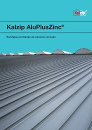
Kalzip AluPlusZinc<br />
AluPlusZinc from Kalzip GmbH is a fusion<br />
of two of the most established materials<br />
in industry – aluminium and zinc. Manufactured<br />
according to the most stringent<br />
quality standards, this is a technically advanced<br />
product which sets new standards.<br />
It combines stunning aesthetics with the<br />
highest quality materials to achieve design<br />
perfection.<br />
The patented PEGAL process produces a<br />
durable fusion between aluminium and zinc.<br />
An additional surface treatment creates a<br />
stable patina with exceptionally high resistance<br />
to the effects of weathering. Indeed,<br />
tests in accordance with DIN 50017 KFW<br />
(cyclic condensate tests) in addition to HCT<br />
tests have proven that Kalzip AluPlusZinc<br />
out performs conventional zinc surfaces in<br />
terms of resistance to corrosion. This surface<br />
finish creates an appearance of classic<br />
elegance, which makes it ideal for a wide<br />
range of applications.<br />
Kalzip AluPlusZinc offers unique<br />
product advantages:<br />
• Zinc patina with surface protection<br />
• Sophisticated, traditional impression<br />
• Bright surface<br />
• Longevity due to aluminium core<br />
• UV-resistant<br />
Kalzip AluPlusPatina<br />
Special surface treatment of the pre weathered,<br />
stucco-embossed profiled sheets<br />
significantly reduces their natural sheen,<br />
thereby creating a new and attractive design<br />
with a high-quality appearance. With<br />
charac teristics comparable to those of an<br />
aluminium profiled sheet which has been<br />
weathered over years, this elegant and<br />
matt surface pro vides roofs and facades<br />
with impressive style.<br />
The natural ageing process, which the<br />
profile sheets undergo during exposure to<br />
weathering, is not hindered and pro ceeds<br />
in the usual manner. In addition to the new<br />
and attractive surface finish, and the highly<br />
diverse design opportunities which this<br />
creates for planners and architects, Kalzip<br />
AluPlusPatina offers all the product advantages<br />
of the standard, stucco-embossed<br />
design.<br />
Advantages of the product:<br />
• Resistant to weathering and to<br />
aggressive environmental influences<br />
• Considerably less light reflection<br />
• Matt look due to pre-weathered surface<br />
• Decreased glare due to diffuse light<br />
reflections<br />
• Dirt-repellent surface<br />
– insensitive to fingerprints<br />
• Available in a stucco embossed<br />
or smooth finish<br />
• UV-resistant<br />
Coil-Coating<br />
Liquid lacquer is rolled onto the alumi ni um<br />
layer in a coil coating process. These colour<br />
coated coils are then used to roll-form the<br />
Kalzip profiles.<br />
Kalzip profile boards<br />
with polyester coating<br />
The coating is robust and insensitive to<br />
scratching; it has very good forming characteristics<br />
and good resistance to weathering<br />
and UV light. Kalzip profiled sheets<br />
in a polyester execution are mainly used<br />
in locations with normal environmental<br />
influences.<br />
Kalzip profiled sheets<br />
with a PVDF coating<br />
This coating is particularly well suited for<br />
aggressive environments and extreme<br />
climatic conditions, e.g. proximity to salt<br />
water. Profiled sheets with a PVDF coating<br />
are characterised by outstanding UV-resistance,<br />
have very good forming characteristics<br />
and are primarily used for façade<br />
design.<br />
Kalzip ProTect coating<br />
For the protection of the surfaces, Kalzip<br />
additionally offers a high-quality and extraordinarily<br />
weather-resistant special highend<br />
coating on the basis of a polymer<br />
technology using fluorocarbon (FLP). It is<br />
characterised by extremely high resistance<br />
to scratching, maximum colour and gloss<br />
stability as well as considerably higher<br />
surface hardness and temperature resistance.<br />
10 Kalzip
The system and its components<br />
Kalzip colours<br />
Protective plating<br />
Characteristics of the ProTect coating:<br />
• Available for RAL, NCS and metallic<br />
shades of colour<br />
• Outstanding long-term characteristics<br />
with minimum chalking tendency<br />
• Very good dirt repulsion due to a<br />
Teflon-like behaviour, thus less cleaning<br />
effort necessary<br />
• Resistant to chemicals and also to<br />
aggressive emissions such as aircraft<br />
exhaust gases<br />
• An ‘anti-graffiti effect’ is achieved by<br />
means of the FLP technology and an<br />
additional clear lacquer, offering<br />
effective protection against vandalism<br />
• Also available with high gloss surfaces<br />
• Corresponds to the test conditions<br />
of the Florida test (outdoor storage for<br />
over 20 years)<br />
Colour range<br />
In addition to the diverse range of shape<br />
variants, Kalzip also offers a wide range of<br />
colour and surface finishes which provides<br />
optimum design freedom and safety. Special<br />
colours are available on request.<br />
Controlled colour quality<br />
The aluminium strips coated using the<br />
coil coating process pass through a large<br />
number of elaborate processing steps.<br />
Depending on the type of coating, they<br />
are subjected to different pretreatments<br />
and painted in the desired colour or sealed<br />
with a clear varnish. Aluminium strips with<br />
a single-sided coating are given a coat of<br />
protective varnish on the rear side.<br />
In order to achieve a weather-resistant<br />
and colourfast coating, only high-quality<br />
enamels on a polyester, PVDF or CFTE<br />
basis are used. The coil coating process<br />
is monitored according to the standards<br />
of the ECCA (European Coil Coating Association).<br />
Important criteria here are: colour,<br />
degree of gloss, paint coating thickness,<br />
paint hardness, paint adhesion and ductility.<br />
There are additional long-term tests such<br />
as the acid salt spray test, QUV-B test,<br />
condensation climate in an atmosphere<br />
containing SO 2<br />
and outdoor weathering<br />
tests in an aggressive environment.<br />
Plating<br />
Plated with a special alloy, the aluminium<br />
core is additionally protected. The thickness<br />
of the protective layer is only 4 % of<br />
the material itself. During the rolling process,<br />
a permanent joint between the plating and<br />
the core material is achieved.<br />
The electro-chemical potential of the plating<br />
is lower than that of the core material<br />
and therefore has the effect of a sacrificial<br />
anode in case of exposure to corrosive<br />
agents. Corrosion does not attack the core<br />
material but is limited to the plating. This<br />
protection remains effective even if the<br />
surface of the sheets is damaged.<br />
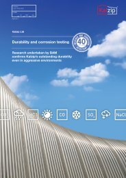
The performance of the protective plating<br />
has been proved by several tests carried<br />
out by “Bundes anstalt für Materialforschung<br />
und Prüfung (BAM) in Berlin” (German<br />
Federal Institute for material research and<br />
testing).<br />
The advantages in summary:<br />
• Reduced surface reflection compared<br />
to Alu-Natur<br />
• Calm metallic impression<br />
• Salt water resistant<br />
• Even surface greying<br />
• Resistant to weathering and to<br />
aggressive environmental influences<br />
Protective film<br />
At the customer‘s request and/or due to<br />
production requirements, surfaces are<br />
protected against possible damage with<br />
an appropriate film. It must be ensured<br />
that the film is removed within two weeks<br />
of delivery in order to prevent increased<br />
effort for its removal.<br />
Metallic enamels<br />
In the case of metallic enamel coating,<br />
variations in colour may occur between<br />
different production batches. For this<br />
reason it is advisable to take care when<br />
planning facades or visible roofs to make<br />
sure that the profiled sheets are roll formed<br />
from the same batch of material.<br />
Anti-condensation and<br />
anti-drum coatings<br />
If required the profile sheets can also be<br />
fitted with an anti-condensation or antidrum<br />
coating.<br />
Kalzip 11
The system and its components<br />
3.4 Accessories<br />
Gable bar verge<br />
Eaves<br />
Transition sheet (Al)<br />
for rising walls and gable ends<br />
Rib filler<br />
seals the edge of the eaves<br />
Drip angle (Al)<br />
stiffens the bottom sheet and<br />
makes the water drip into the gutter<br />
indispensable for static reasons!<br />
Compressible adhesive tape<br />
prevents flow-back of rain water<br />
Kalzip vapour barrier<br />
avoids air flow and diffusion<br />
12 Kalzip
The system and its components<br />
Drip angle<br />
Ridge<br />
Spacer section (Al)<br />
compensates height differences<br />
to the end plate<br />
Form filler<br />
ends flush with the ridge<br />
Ridge profile (Al)<br />
protects the form filler against UV<br />
radiation and reduces wind pressure<br />
Gable end profile (Al)<br />
provides fastening device<br />
for joining sheets<br />
Gable end hook (Al)<br />
secures gable end against storm<br />
Reinforcing profile for verge flashing (Al)<br />
stiffens the flange<br />
Kalzip 13
The system and its components<br />
3.5 Components for roof superstructures<br />
and safety appliances<br />
SolarClad<br />
Step<br />
14 Kalzip
The system and its components<br />
left to right:<br />
Seam clip aluminium,<br />
Cable clip,<br />
Seam clip (stainless steel)<br />
Snow guard<br />
Kalzip fall arrest system<br />
Soaker frame<br />
Kalzip 15
Kalzip range of applications<br />
4. Kalzip range of applications<br />
Within the context of the amendment of the<br />
German energy saving regulations (EnEV<br />
2009), the energetic requirements of external<br />
structural components are an important<br />
component of the new energy saving regulations<br />
for improving the sustainable energy<br />
efficiency of buildings in the context of<br />
economic viability and in accordance with<br />
the state of the art.<br />
On the basis of newly-developed materials,<br />
Kalzip system components make a significant<br />
contribution to EnEV-compliant roof<br />
structures.<br />
Application specific system build-up<br />
Kalzip sheets can be used both for ventilated<br />
and non-ventilated roofs as well as<br />
for any roof shape or down to a minimum<br />
pitch of 1.5°.<br />
Furthermore it may be combined with any<br />
kind of support or substructure. The system<br />
depends on the special requirements of<br />
the individual application.<br />
The likely effects of snow, wind, humidity<br />
and weathering are fully taken into account.<br />
Kalzip can easily be configured to provide<br />
the highest levels of thermal insulation.<br />
Thermal insulation requirements can be<br />
easily fulfilled. The thickness of the insulation<br />
can be perfectly adapted to the<br />
individua lrequirements of the building.<br />
In addition, the system offers advanced<br />
detailed solutions for effective interior or<br />
exterior draining of the roof which means<br />
a high degree of reliabilty throughout the<br />
long serviceable life of the roof.<br />
Insulated roof systems are the norm<br />
The main applications for Kalzip roof systems<br />
are insulated roof structures supported by<br />
trapezoidal steel, timber linings, purlins or<br />
concrete elements.<br />
• Chemically neutral, fibrous insulating<br />
materials as specified by e.g. the<br />
German DIN 18 165 are recommended<br />
as suitable thermal insulation. The insulation<br />
is laid into position and is then<br />
compressed to its required final thickness<br />
when are installed the profiled<br />
Kalzip sheets on top. There should be<br />
no cavity between the Kalzip sheets<br />
and the insulation.<br />
• A vapour barrier must be incorporated.<br />
Properly installed it provides the<br />
required air tightness.<br />
• Of course, ventilated roof implementations<br />
are also possible<br />
• The sound reduction values of the<br />
standard roof are subsequently<br />
described. Further improvements<br />
can be achieved by including<br />
additional layers.<br />
• Information on U values can be found in<br />
chapter 7, Kalzip dimensioning tables,<br />
starting from page 47.<br />
Non-ventilated Kalzip roof<br />
on a trapezoidal steel deck<br />
R’w = ~ 35 dB (A)*<br />
Non-ventilated Kalzip roof<br />
on a trapezoidal steel deck<br />
This very economical roof system is used<br />
both for industrial and residential buildings.<br />
In order to make sure that there are no air<br />
cavities under the Kalzip roof skin, compressible<br />
thermal insulation is used. Incorporated<br />
within the roof system the insulation<br />
material is compressed by approx. 20 mm.<br />
The loading on the top skin is not transferred<br />
to the inner skin as an evenly distributed<br />
load but rather at set points via the secret<br />
fixing clips. The design roof load must be<br />
increased by 15 % when dimensioning the<br />
trapezoidal steel sheets. The clips must<br />
be staggered on the inner sheet to make<br />
sure that the load is evenly distributed<br />
across all corrugations of the inner<br />
sheet.<br />
* varies depending on thickness and material qualities<br />
16 Kalzip
Kalzip range of applications<br />
Non-ventilated Kalzip roof<br />
on purlins with trapezoidal inner sheet<br />
R’w = ~ 35 dB (A)*<br />
Non-ventilated Kalzip roof<br />
on purlins with trapezoidal inner sheet<br />
If the roof is supported on purlins, the inner<br />
sheet has to be oriented parallel to the<br />
top layer. If the module of the inner sheet<br />
does not correspond with the Kalzip elements<br />
a top hat section must be installed<br />
to support the clips. If the Kalzip sheets<br />
can span the existing spacing of the purlins,<br />
the top hat sections will be positioned<br />
on top of the purlins. By this way the inner<br />
sheet carries only the weight of the insu -<br />
lation.<br />
For larger purlin spans additional top hat<br />
sections are required. In this instance, part<br />
of the load needs to be transferred by the<br />
inner sheet.<br />
Non-ventilated Kalzip roof<br />
on timber rafters with visible timber lining<br />
R’w = ~ 38 dB (A)*<br />
Non-ventilated Kalzip roof on timber<br />
rafters with visible timber lining<br />
In residential buildings the roof system is<br />
frequently built-up using wooden rafters<br />
with visible timber lining. This is advantageous,<br />
because:<br />
1. there is a clear separation between<br />
the trades of carpenters, roofers etc.<br />
2. a continuous flat vapour barrier<br />
can be installed.<br />
* varies depending on thickness and material qualities<br />
The clips can only be fixed directly in the<br />
timber lining if this has a minimum thickness<br />
of 23 mm. A minimum thickness of<br />
19 mm applies for flat press boards, and<br />
18 mm for OSBs. In both cases the fastener<br />
is visible from below. If the timber lining<br />
is too thin, then a timber purlin must be<br />
installed over the lining and attached to<br />
the rafters. See Kalzip approval No.<br />
Z-14.1-181.<br />
Kalzip 17
Kalzip range of applications<br />
Kalzip DuoPlus 100 and Kalzip Duo 100<br />
on a concrete substructure<br />
R’w = mainly dependent on concrete<br />
Kalzip DuoPlus 100 and Kalzip Duo 100<br />
on a concrete substructure<br />
The Kalzip DuoPlus and Kalzip Duo system<br />
can likewise be installed on a concrete sub -<br />
structure. In the case of a solid concrete slab,<br />
the DuoPlus rails can be arranged at a 90°<br />
angle to the Kalzip. The rotary clip rails are<br />
fixed using approved dowels (SFS MBR-X-<br />
S4-HX-10x160). The dowels are arranged<br />
alternately in the rails. The distance between<br />
the rails depends on the static calculation.<br />
In the case of slabs made of porous<br />
concrete or non-solid concrete slabs, the<br />
DuoPlus rails are arranged at an angle of<br />
less than 45° to the Kalzip. The dowelling<br />
possibilities must be precisely checked in<br />
each individual case and statically calculated.<br />
The choice of approved dowels must be<br />
matched precisely to the concrete material.<br />
Kalzip DuoPlus 100<br />
R’w = ~ 43 dB (A)*<br />
Kalzip DuoPlus 100<br />
The Kalzip DuoPlus 100 system combines<br />
the advantages of rigid insulation with the<br />
constructional possibilities offered by the<br />
conventional Kalzip roofing system. The<br />
special design is almost cold-bridge free<br />
and has excellent sound absorption properties.<br />
An aluminium rail is placed on the<br />
100 mm thick rigid thermal insulation and<br />
is fixed onto the substructure through the<br />
insulation. Special clips are inserted in the<br />
rail and are adjusted to suit the respective<br />
conditions. Connection of the individual<br />
clips to the rail is not necessary. The patented<br />
and type-tested system consists of<br />
rigid thermal insulation, DuoPlus rail, Duo-<br />
Plus clip and connecting elements to secure<br />
the DuoPlus rail, the compressible heat<br />
insulation and the Kalzip profiles sheets.<br />
Kalzip Duo 100<br />
R’w = ~ 41 dB (A)*<br />
Kalzip Duo 100<br />
If there are no specific sound insulation<br />
requirements then the Kalzip Duo 100<br />
system can be used, whereby a full layer<br />
of rigid thermal insulation is not necessary.<br />
The base for the Kalzip DuoPlus 100 is<br />
simply provided by rigid insulation strips<br />
with a width of 24 cm and a thickness of<br />
10 cm. The resulting spaces are filled with<br />
soft heat insulation or low-priced rigid<br />
insulating material. In the case of Kalzip<br />
DuoPlus 100, rigid thermal insulation only<br />
needs to be used in those areas specified<br />
by the statistical requirements. The rigid<br />
thermal insulation is replaced by a layer of<br />
soft insulation in all areas where no reduction<br />
in snow loads is required.<br />
* varies depending on thickness and material qualities<br />
18 Kalzip
Kalzip range of applications<br />
Kalzip NatureRoof<br />
Kalzip NatureRoof<br />
All roof designs described above can be<br />
transformed into a Kalzip NatureRoof<br />
providing that the design requirements<br />
are taken into consideration and Kalzip<br />
65/333 is being used. Kalzip NatureRoof<br />
comprises an efficient draining mat to<br />
control the integral water management<br />
and a special substrate sup porting a<br />
vegetation layer for extensive landscaping<br />
with sedum plants. All components for the<br />
Kalzip NatureRoof outside Germany are<br />
available only on request.<br />
Technical data:<br />
Min. roof pitch: 1,5°<br />
Max. roof pitch: 15°<br />
Additional weight (wet): 0.9 kN/m 2<br />
Shear protection: from 5°<br />
Kalzip FOAMGLAS ® System<br />
as a standard solution<br />
Kalzip FOAMGLAS ® System<br />
as a combination solution<br />
* varies depending on thickness and material qualities<br />
Kalzip FOAMGLAS ® System as<br />
a standard and combined solution<br />
This roof design and the system components<br />
used are particularly suitable<br />
for building projects which place high<br />
demands on ensuring that the roof system<br />
is free from condensation and where<br />
there is therefore a permanent risk of<br />
condensation formation. The Kalzip<br />
FOAMGLAS ® System offers a high level of<br />
energy efficiency as the thermal insulation<br />
is airtight and impervious to water vapour.<br />
What’s more, there is no mechanical attachment<br />
between the Kalzip profiled<br />
sheets and the supporting structure. This<br />
means there is no coldbridging. As<br />
FOAMGLAS ® is impervious to moisture<br />
penetration the insulation can also act as<br />
a watertight substructure.<br />
The FOAMGLAS ® slabs are bonded to<br />
different substructures using either a coldbonding<br />
agent or hot bitumen. In order to<br />
attach the composite clips, the galvanized<br />
steel claw plates are inserted under heat<br />
in a fixed installation plan taking into account<br />
the respective roof geometry. The<br />
composite clips are installed on the claw<br />
plates using the recommended fastening<br />
elements. The Kalzip profiled sheets are<br />
installed in the usual manner and are friction-fitted<br />
together. In order to ensure<br />
economic efficiency, the thickness of the<br />
compressible thermal insulation can be<br />
varied. FOAMGLAS ® has a minimum thickness<br />
of 80 mm.<br />
The manufacturer’s installation regulations<br />
are to be observed. The installation and dimensioning<br />
are governed by the Kalzip approval<br />
Z-14.4-475.<br />
Kalzip 19
Kalzip range of applications<br />
Kalzip AF<br />
Kalzip AF profiled aluminium sheets are<br />
especially designed for installation above<br />
rigid support layers. Under the trade mark<br />
“ProDach insulating system” Rockwool<br />
offers an accessible, compression-proof,<br />
water repellent mineral wool insulating<br />
board featuring a special fixing system.<br />
Kalzip AF is available in sheet lengths up<br />
to 50 m (longer lengths are available on<br />
request).<br />
The level ribless profile provides a smooth<br />
and attractive appearance. The AF system<br />
offers outstanding thermal as well as<br />
acoustic properties. Kalzip AF profiled<br />
aluminium sheets are not only used in<br />
combination with the ProDach-insulation<br />
system but may also be used with FOAM-<br />
GLAS ® insulation and timber lining.<br />
The twin layer Prorock insulating<br />
board: the ideal base for Kalzip AF<br />
• non combustible<br />
• very efficient thermal insulation<br />
and acoustic properties<br />
• dimensionally stable<br />
• vibration dampening<br />
• open for diffusion<br />
• high accessibility during<br />
installation and maintenance<br />
• safe absorption of pressure<br />
and suction loads<br />
Assembly<br />
The corrosion-proof and weather resistant<br />
Kalzip AF aluminium external skin is fixed<br />
with clips in the usual way. How ever, and<br />
this is the distinctive feature of the ProDach<br />
insulation system, rather than being fixed<br />
directly to the substruc ture the skin is<br />
fixed instead to special U-rails embedded<br />
in the insulation material.<br />
The stainless steel system fasteners connecting<br />
the U-rails to the substructure of<br />
the roof penetrate the insulation material<br />
only locally. This almost entirely eliminates<br />
the effect of cold/heat and sound bridging.<br />
Kalzip AF with ProDach-insulation<br />
on trapezoidal steel deck<br />
R’w = ~ 42 dB (A)*<br />
Kalzip AF with ProDach-insulation<br />
on trapezoidal steel deck<br />
In order to meet increased demands for<br />
sound reduction and to reduce cold/heat<br />
bridges it is advisable to install the ProDach<br />
Insulation System. Fixing rails are embedded<br />
in the top-side of the insulation material<br />
and fixed to the trapezoidal steel deck.<br />
* varies depending on thickness and material qualities<br />
20 Kalzip
Kalzip range of applications<br />
Kalzip AF with ProDach-insulation<br />
on timber rafters with formwork<br />
R’w = ~ 45 dB (A)*<br />
Kalzip AF with ProDach-insulation<br />
on timber rafters with formwork<br />
With this type of roof, a timber lining which<br />
remains visible serves as a supporting<br />
element. This structure has proved to be<br />
ideal for residential buildings and other<br />
buildings of similar use. The potential<br />
extends from public buildings to multipur<br />
pose halls and sports-arenas. The<br />
rails are invisibly fixed to the rafters.<br />
There are no visible joints or fasteners.<br />
Kalzip AF with the insulation<br />
layer at rafter level<br />
Kalzip AF with the insulation layer<br />
at rafter level*<br />
This structure is comparable to tradi tional<br />
standing seam systems. It is frequently<br />
used in order to minimise the overall height<br />
of the roof structure. If there is an air gap<br />
under the timber lining adequate ventilation<br />
is essential.<br />
With this in mind, we recommend filling<br />
the total height of the rafters with insulating<br />
material for efficient performance. A vapour<br />
barrier beneath the thermal insulation is<br />
also of critical importance.<br />
For the minimum thickness of timber materials,<br />
see Kalzip approval Z-14.1-181.<br />
Kalzip AF on FOAMGLAS ® insulation<br />
Kalzip AF on FOAMGLAS ® insulation*<br />
Kalzip AF can also be used on the proven<br />
FOAMGLAS ® insulation. Various installation<br />
methods are possible. The method shown<br />
here using the L-shaped claw plate does<br />
entirely without a mechanical connection<br />
between the Kalzip profiles and the support<br />
skin and is free of thermal bridges.<br />
The composite clips employed allow optimum<br />
sliding of the profiles in the case of<br />
a temperature-related change of length.<br />
A thermally stable isolation layer must be<br />
arranged between Kalzip and a bituminous<br />
secondary covering.<br />
* varies depending on thickness and material qualities<br />
Kalzip 21
Kalzip range of applications<br />
Kalzip Solar Power <strong>Systems</strong><br />
When referring to photovoltaic systems,<br />
architects make a distinction between<br />
roof-mounted and roof-integrated systems.<br />
Kalzip GmbH offers solar power systems<br />
which are perfectly coordinated with Kalzip<br />
for both options.<br />
Kalzip AluPlusSolar<br />
Trapezoidal substructure<br />
Because of the small dead weight and the<br />
lack of structural height, the additional<br />
load on the main support structure remains<br />
very low, which positively affects the costs<br />
of the building. These advantages are par -<br />
ticularly effective in the case of renovation<br />
measures. The problem of the existing<br />
support structure not being able to absorb<br />
additional wind and snow loads, which<br />
frequently arises with crystalline systems,<br />
usually does not arise with Kalzip Solar<br />
systems. The necessary static examination<br />
of the existing building can often be omitted<br />
due to the low loads.<br />
Kalzip AluPlusSolar<br />
The new Kalzip AluPlusSolar profiled sheets<br />
are the first to combine a system of solar<br />
power generation using roof-integrated<br />
photovoltaics with the maximum freedom<br />
of architectural design to create stunning<br />
buildings. The solar laminates are flexible<br />
and extremely durable. Depending on the<br />
particular roof design, they are permanent ly<br />
bonded to straight, convex or concave<br />
Kalzip aluminium profiled sheets. The flexibility<br />
of Kalzip AluPlusSolar can accommodate<br />
barrel vault or monopitch roofs,<br />
as well as customised roof designs.<br />
Kalzip AluPlusSolar is available as a fully<br />
integrated system, including inverter and<br />
accessories, on the AF 65/537/1.0 mm<br />
profiled sheet in RAL 9006 (other colours<br />
available on request). The solar film, available<br />
in two lengths, is laminated in the<br />
factory and then permanently bonded to<br />
the outer surface of the Kalzip profiled<br />
sheets. This film will subsequently generate<br />
the power in the photovoltaic system.<br />
Kalzip profiled sheets which have already<br />
been installed cannot be retrofitted with<br />
laminated solar film. However, existing<br />
Kalzip roofs can be retrofitted with Kalzip<br />
SolarClad. In addition to a roof-integrated,<br />
regenera tive method of energy production,<br />
Kalzip Solar<strong>Systems</strong> also offer the opportunity<br />
of generating energy in the facade.<br />
We can send you detailed information on<br />
request.<br />
The silicon thin-film solar cells use triplejunction<br />
technology to generate more<br />
energy in diffuse light conditions than<br />
crystalline solar cells of the same rated<br />
power and are therefore ideal for use in<br />
European regions. The durability of the<br />
Kalzip profiled sheets and the guaranteed<br />
efficiency of the solar modules now make<br />
it possible to create contemporary, modern<br />
buildings which combine maximum freedom<br />
of architectural design with the integration<br />
of ecological concepts.<br />
Planning tips<br />
• Kalzip profiled sheets cannot be retrofitted<br />
with laminated thin-film solar<br />
modules. We recommend the use of<br />
Kalzip SolarClad.<br />
• Minimum radius in the area where the<br />
rofiled sheets are fitted with modules 13 m.<br />
• Recommended roof pitch min. 5 % (3°).<br />
Safety Class II, design suitability and<br />
approval in accordance with IEC 61646<br />
TÜV Rheinland, Cologne, Germany<br />
For more information, please visit:<br />
www.aluplussolar.com<br />
Technical Data PVL-68 PVL-136 PVL-144<br />
Surface required per kWp [m 2 ] > 22.5 > 22 > 20.5<br />
Module length [m] 2.85 5.50 5,50<br />
Maximum Power (P max ) [W p ] 68 136 144<br />
Voltage at P max (V mpp ) [V] 16.50 33 33<br />
Current at P max (I mpp ) [A] 4.13 4.13 4.36<br />
Open circuit voltage V OC [V] 23.10 46.20 46.20<br />
Short-circuit current I SC [A] 5.10 5.10 5.30<br />
Series fuse rating, nom./ blocking diode rating, nom. [A] 8 8 8<br />
Maximum DC system voltage [V] 1000 1000 1000<br />
Connection<br />
reverse side,terminal housing assembly IP65, 50 cm connecting<br />
cable MC-FlexSol-XL (4 mm 2 ), male connector MC 4<br />
Weight in kg per m 2 roof size 2.7 2.7 2.7<br />
NOTE: The values specified represent stabilised values (± 5%). During the first 8-10 weeks of operation, power output may be higher<br />
by 15%, operating voltage may be higher than 11% and operating current may be higher by 4%.<br />
22 Kalzip
Kalzip range of applications<br />
Kalzip SolarClad parallel to standing seams,<br />
vertical<br />
Kalzip SolarClad perpendicular to standing seam,<br />
horizontal<br />
Kalzip SolarClad elevated from roof<br />
Kalzip SolarClad<br />
Kalzip SolarClad is a photovoltaic cladding<br />
which has been optimised for use in building<br />
envelopes. Its flexibility and versatility<br />
enable solar modules to be integrated into<br />
virtually all standing seam systems made<br />
from a variety of materials. Kalzip Solar-<br />
Clad is a retrofit solar solution which can<br />
be harmo niously integrated into existing<br />
building structures and also used in new<br />
builds.<br />
The system consists of extremely robust<br />
thin-film modules made from amorphous<br />
silicon (a-Si), bonded onto aluminium system<br />
rails, which can be installed on any<br />
metal roof system in a non-penetrative<br />
manner. These extremely lightweight module<br />
units are suitable for all roof shapes.<br />
Kalzip SolarClad is supplied as a com plete<br />
system, including inverters, for different<br />
standing seam designs. The solar film,<br />
available in two different lengths, is laminated<br />
onto Kalzip system rails in the factory<br />
to ensure high quality and fast installation.<br />
The solar laminates generate power from<br />
the sun as soon as they are connected.<br />
Kalzip SolarClad is suitable for all roof<br />
shapes with a pitch up to a maximum of<br />
60° from horizontal. As the system is extrem<br />
ely lightweight, this generally means<br />
there are no additional structural requirements<br />
for the roof. Kalzip SolarClad is<br />
therefore suitable for all roof structures<br />
and all Kalzip widths.<br />
Technical Data PVL-68 PVL-136 PVL-144<br />
Surface required per kWP (installation parallel to standing seams) [m 2 ] > 19 > 18.50 > 18<br />
Module length [m] 2.85 5.50 5,50<br />
Maximum Power (P max ) [W p ] 68 136 144<br />
Voltage at P max (V mpp ) [V] 16.50 33 33<br />
Current at P max (I mpp ) [A] 4.13 4.13 4.36<br />
Open circuit voltage V OC [V] 23.10 46.20 46.20<br />
Short-circuit current I SC [A] 5.10 5.100 5.30<br />
Series fuse rating, nom./ blocking diode rating, nom. [A] 8 8 8<br />
Maximum DC system voltage DC [V] 1000 1000 1000<br />
Connection<br />
reverse side, terminal housing assembly IP65, 50 cm connecting<br />
cable MC-FlexSol-XL (4 mm 2 ), male connector MC 4<br />
Weight in kg per m 2 (installation parallel to standing seams) 6.1 6.1 6.1<br />
NOTE: The values specified represent stabilised values (± 5%). During the first 8-10 weeks of operation, power output may be higher<br />
by 15%, operating voltage may be higher than 11% and operating current may be higher by 4%.<br />
Kalzip 23
General data and characteristics<br />
5. General data and characteristics<br />
5.1 Roof pitch<br />
The Kalzip system consisting of self supporting<br />
aluminium elements was specially<br />
developed for roofs with pitches down to<br />
1.5° or 2.6 % together with long sheet<br />
lengths. Owing to the attractive appearance<br />
of the modular system, architects<br />
often use this system for visible steep<br />
roofs and increasingly for wall claddings.<br />
Continous falling gradient required<br />
All parts of the roof must have a conti nous<br />
downward gradient towards the draining<br />
system.<br />
Minimum roof pitch<br />
• without horizontal joints 1.5°<br />
respectively 2.6 %<br />
- running from the eaves in one length<br />
- all joints are welded<br />
- factory welded soakers welded into<br />
the roofing skin<br />
• sheets with horizontal joints 2.9° (5%)<br />
- with sealed horizontal joints<br />
- soakers sealed into the roof skin<br />
- Factory welded soakers sealed into<br />
the roof skin<br />
Anomalies<br />
The specification limiting the minimum roof<br />
slope is not applicable along the ridge area<br />
where roof elements run with out joints from<br />
eaves to eaves over the ridge.<br />
5.2 Minimum radii for crimp-,<br />
smooth- and on site curving<br />
Exacting design calls for creative and detailed<br />
solutions. Today curved corners or<br />
arched roofs can be easily achieved by<br />
advanced industrial prefabrication. They<br />
provide modern industrial architecture<br />
with a high level of functional and aesthetic<br />
quality combined with future oriented<br />
perspectives.<br />
The minimum radii for smooth curving<br />
of Kalzip elements are specified on the<br />
following page.<br />
5.2.1 Kalzip Convex<br />
Factory crimp-curved<br />
Cover width (BB)<br />
50/333, 50/429, 65/305, 65/333, 65/400,<br />
65/500, AF 65/333, AF 65/434, AS 65/422<br />
Minimum radius: Ri = 450 mm<br />
Installation width is the actual width of<br />
the assembled sheets. If the clips are<br />
pre-installed the installation width must<br />
be increased.<br />
(Installation width = cover width + 3 mm)<br />
If crimp-curved profiled sheets are<br />
connected with straight ones, the rounded<br />
sheet determines the dimension. It is<br />
recommended to carry out the distribution<br />
in accordance with the measured dimension<br />
of the rounded profiled sheet.<br />
l 2<br />
Profiled sheets lengths:<br />
Straight lengths 500 mm min. to 10.000 mm*<br />
max. Depending on radius and transportation<br />
limitations<br />
* greater lengths on request<br />
Surface finish:<br />
• stucco-embossed<br />
• AluPlusPatina<br />
• Colour coated with protective foil<br />
• AluPlusZinc with protective foil<br />
Please take note when ordering:<br />
Please specify the required dimensions in<br />
accordance to the sketch.<br />
Transportation:<br />
Max. loading height 2.40 m. For any<br />
queries, please contact our logistics<br />
department.<br />
Minimum length of straight end pieces<br />
Ri min l 1<br />
min l 2<br />
[mm] [mm] [mm]<br />
bis 1000 150 150<br />
> 2000 0 0<br />
C<br />
a<br />
DB<br />
l 1<br />
65<br />
R i<br />
R a<br />
C a<br />
= Arc length outside<br />
24 Kalzip
General data and characteristics<br />
5.2.2 Kalzip smooth curved in factory, aluminium<br />
Convex<br />
Minimum curving radii in m<br />
Sheet thickness 0.8 mm 0.9 mm 1.0 mm 1.2 mm<br />
65 / ... 6 5 1.5 1.5<br />
50 / ... 8 5 1.3 1.3<br />
AF 65 / ... 10 8 3.5 3<br />
AS 65 / ... 10 8 3.5 3<br />
Concave<br />
Sheet thickness 0.8 mm 0.9 mm 1.0 mm 1.2 mm<br />
65 / ... 16 14 10 10<br />
50 / ... 12 10 7 6<br />
AF 65 / ... 15 14 10 7<br />
AS 65 / ... 25 16 10 8<br />
Curved and tapered: Please check with our technical department in Koblenz/Germany.<br />
General information<br />
Kalzip AF und AS:<br />
With Kalzip AS and AF profiled sheets, an in -<br />
crease in construction width of up to 20 mm<br />
must be taken into account following curving,<br />
so that an overlap with straight sheets<br />
is not possible.<br />
Smooth-curved Kalzip AF profile sheets can<br />
show signs of increased buckling in the<br />
base plate. As it is impossible for tech nical<br />
production to prevent this buckling, it will<br />
not be accepted as grounds for complaint.<br />
When the optical characteristics of a building<br />
are of increased importance, then<br />
smooth-curved Kalzip AS profile sheets<br />
should be used instead.<br />
Standard:<br />
Constant radius with a short (approx. 400<br />
mm) straight segment at the beginning and<br />
the end of the profile sheet. Any radii below<br />
the standard minimum as well as multiple<br />
radii and/or straight elements in one Kalzip<br />
sheet must be agreed with our technical<br />
department in Koblenz.<br />
It is unavoidable that inter mediate radii occur<br />
in the transition area of different radii as well<br />
as between curved and straight sectors.<br />
Clips must not be located in these areas.<br />
Tolerance limits. Only after consultation<br />
with our technical department in Koblenz.<br />
Special measures are necessary in order<br />
to reach the tolerance limits.<br />
Finish:<br />
• stucco-embossed<br />
• AluPlusPatina<br />
• coated material with protection foil<br />
• AluPlusZinc with protection foil<br />
• Anti-condensation coating on request<br />
Installation width:<br />
For pre-installed clips:<br />
cover width + 3 mm<br />
successive installation of clips:<br />
cover width + 0 to + 3 mm<br />
Length of profiled sheet:<br />
Minimum length 1.5 m. Shorter lengths on<br />
request. The final overall length depends<br />
on the individual radii and possibility of<br />
transport. Minimum length of segment per<br />
radius = 500 mm.<br />
Transportation:<br />
Maximum loading height 2.4 m. It might be<br />
necessary to coordinate details of transportation<br />
with our logistics department.<br />
Transitional area:<br />
If a Kalzip profiled sheet is roll-curved with<br />
several radii, a transitional area is created<br />
in which no clip may be placed (except a<br />
fixed point clip).<br />
This transitional area can be safely estimated<br />
to be ± 300 mm (600 mm in total) if the<br />
two adjacent radii both have the same sign<br />
has, or ± 600 mm (1200 mm in total ) if the<br />
two adjacent radii have different signs, i.e.<br />
from concave to convex or vice versa. It is<br />
necessary to consult the Application Technology<br />
Dept. in Koblenz for a more exact<br />
determination of this transitional area.<br />
Kalzip 25
General data and characteristics<br />
5.2.3 Kalzip supplied in straight form, curved to radius during installation (naturally curved)<br />
The values given are not standard values. They do not serve as a replacement for project specific consultations.<br />
Convex<br />
Kalzip<br />
Type<br />
Sheet thickness<br />
(mm)<br />
Radii<br />
(m)<br />
max. supporting space<br />
(m)<br />
65/305 0.8 36 1.5 +3<br />
65/333 0.9 40 1.6 +3<br />
65/400 1.0 48 1.8 +3<br />
1.2 55 2.0 +3<br />
50/333 0.8 37 1.5 +2<br />
50/429 0.9 37 1.5 +2<br />
1.0 40 1.5 +2<br />
1.2 43 1.8 +2<br />
AS 65/422 0.8 50 1.5 +2<br />
0.9 55 1.5 +2<br />
1.0 60 1.5 +2<br />
1.2 70 1.8 +2<br />
Kalzip AF Profile cannot be naturally curved. Special forms with beading are available on request.<br />
Minimum curving radii in m<br />
Increase in construction<br />
width (mm)<br />
Concave<br />
Kalzip<br />
Type<br />
Sheet thickness<br />
(mm)<br />
Radii<br />
(m)<br />
max. supporting space<br />
(m)<br />
65/305 0.8 40 1.5 +3<br />
65/333 0.9 45 1.6 +3<br />
65/400 1.0 50 1.8 +3<br />
1.2 60 2.0 +3<br />
50/333 0.8 38 1.5 +2<br />
50/429 0.9 40 1.6 +2<br />
1.0 42 1.8 +2<br />
1.2 45 2.0 +2<br />
AS 65/422 0.8 50 1.5 +2<br />
0.9 55 1.6 +2<br />
1.0 60 1.8 +2<br />
1.2 70 2.0 +2<br />
Kalzip AF Profile cannot be naturally curved. Special forms with beading are available on request.<br />
Increase in construction<br />
width (mm)<br />
General information<br />
Naturally curved:<br />
The profile sheets are supplied in straight<br />
form and are curved by hand to the respective<br />
radii during installation.<br />
Cover width:<br />
Depending on the radius, the nominal<br />
width (construction width) must be increased<br />
to the cover width (installed width).<br />
Support spacing:<br />
When the supporting spacings are too<br />
large the supports will appear as polygon<br />
lines.<br />
Accessibility:<br />
Due to the risk of buckling, access to the<br />
sheets must not be gained without load<br />
spreading equipment.<br />
Finish:<br />
• stucco-embossed<br />
• AluPlusPatina<br />
• coated material with protection foil<br />
• AluPlusZinc with protection foil<br />
• Anti-condensation coating on request<br />
• without protection foil on request<br />
Appearance:<br />
The minimum radii outlined above reflect<br />
current experiences. As it is necessary to<br />
curve the profile sheets to the respective<br />
radius, buckling cannot be ruled out.<br />
Installation tip:<br />
It is advisable to provide a support on the<br />
ridge over which the profile sheets can be<br />
curved. Installation should take place from<br />
the direction of the non-covered side.<br />
Packaging:<br />
If the pitch is greater than 1.70 m, then<br />
this information must be supplied when<br />
ordering. The reason for this is that special<br />
packaging may be necessary.<br />
26 Kalzip
General data and characteristics<br />
5.3 Tapered shapes<br />
Tapered Kalzip profile sheets have become<br />
increasingly significant for roofing appli ca -<br />
tions as they can be formed into a diverse<br />
range of shapes. A roof can offer more<br />
than just protection: it can enable a building<br />
to achieve architectural perfection. In<br />
order to achieve the perfect structure, it<br />
is necessary to take into account several<br />
fundamental considerations. The cover<br />
widths are between 230 and 740 mm. Furthermore,<br />
accessibility is limited.<br />
The bottom sheet must be additionally<br />
supported by rigid insulation. Load distri buting<br />
walkways must be provided. In order<br />
to ensure that the bottom sheet is adequately<br />
rigid, it is essential to incorporate<br />
an eaves angle.<br />
The full surface is always covered with foil.<br />
Anti-condensation coating is only subsequently<br />
available in the spraying process.<br />
Aquasine coating is not possible. Tapered<br />
Kalzip sheets must be installed on the roof<br />
in accordance with the installation instructions.<br />
It is advisable to compare the actual<br />
dimensions of the substructure with the<br />
dimensions stated on the installation instructions<br />
before production in the factory<br />
begins. Larger building tolerances can<br />
require repartitioning of the area which is<br />
to be covered. The tables on the following<br />
page apply to a sheet width of 500 mm.<br />
Finish:<br />
• stucco-embossed<br />
• AluPlusPatina<br />
• soated material with protection foil<br />
• AluPlusZinc with protection foil<br />
Profile types available Kalzip 65/… und 50/… Kalzip AF… Kalzip AS…<br />
Minimum construction width 230 mm 170 mm<br />
Maximum width 740 mm 1 740 mm 1<br />
Minimum length 1500 mm 1500 mm<br />
Maximum length Dependent on transport Dependent on transport<br />
not possible<br />
Plate thicknesses 0.80 – 1.20 mm 0.80 – 1.20 mm<br />
Curved and tapered<br />
Possible for construction widths of 230 – 620 mm.<br />
Only following approval from the technical department in Koblenz.<br />
1<br />
Applies only to stucco-embossed and colour-coated Kalzip profile sheets. Other material combinations are available on request.<br />
Joint carried out as a welded joint<br />
or step joint<br />
min.<br />
Self-supporting up to a<br />
construction width of 500 mm<br />
max.<br />
For construction widths exceeding 500 mm<br />
only with additional support and clips spaced<br />
at 1.0 m max.<br />
Installation examples with joints<br />
Kalzip 27
General data and characteristics<br />
5.4 Kalzip XT free-form profiled sheets<br />
Kalzip type 65 /… / 1.0 mm<br />
The XT production technology allows difficult<br />
roof and wall surfaces, even if they are<br />
free-form surfaces, to be clad with Kalzip<br />
profiled sheets. Different radii, convex and<br />
concave, as well as side radii, bulges and<br />
narrowings can thereby be combined in<br />
one profiled sheet.<br />
The limit values are subjected to constant<br />
changes and improvements. The combination<br />
of the various possibilities in particular<br />
has a big influence on the various limit<br />
values.<br />
The following, non-binding limit values<br />
serve as an aid to orientation:<br />
Convex curved 2.50 m<br />
Concave curved 10.0 m<br />
Side radius 20.0 m<br />
Minimum width 275 mm*<br />
Maximum width 740 mm*<br />
The maximum length depends on the<br />
transportation possibilities and the basic<br />
material available. The minimum length<br />
depends on the contour and on the production<br />
procedure and must be examined<br />
in detail.<br />
For reasons related to production, excess<br />
lengths of at least 400 mm are necessary<br />
at the ends of the XT profiled sheets; these<br />
have to be cut off on the building site. They<br />
offer additional flexibility in the alignment<br />
of the profiled sheets.<br />
The quality of the finished Kalzip surface<br />
depends to a large extent on the quality<br />
of the spacer structure between the support<br />
structure and the outer skin. It must<br />
be adjustable in order to be able to compensate<br />
for building tolerances.<br />
The planning and installation of XT profiled<br />
sheets requires a great deal of effort.<br />
XT constructions are planned completely<br />
in 3D. A 3D GUI, preferably in the format<br />
.3dm (Rhinoceros), is necessary for editing.<br />
The suitability of other file formats must<br />
be checked.<br />
* Applies only to stucco embossed Kalzip profiled<br />
sheets. Other material/combinations on request.<br />
Hospital, Emmen (NL)<br />
Architect: A/d Amstel Architecten<br />
28 Kalzip
General data and characteristics<br />
5.5 Accessibility/fall arrest systems<br />
For maintenance and cleaning Kalzip<br />
sheets are accessible both during and after<br />
installation without any load distributing<br />
measures. As far as the installation is con -<br />
cerned this will only be valid if the profiled<br />
sheets are zipped on at least one side. The<br />
following table specifies the critical spans<br />
up to which the profiled sheets are accessible<br />
without any additional measures.<br />
It is advisable to install walkways leading<br />
to any units requiring regular maintenance<br />
or operational elements such as daylight<br />
units, chimneys or heating plants. When<br />
exceeding the critical span, load distributing<br />
elements such as wooden planks of<br />
a minium cross section of 4 x 24 cm and<br />
a maximum length of 3 m have to be<br />
installed length – or crosswise over the<br />
Kalzip sheets.<br />
In situations where no rigid thermal insulation<br />
has been installed along the ridge<br />
and eaves areas, the sheets in these parts<br />
of the roof should not directly be walked<br />
on. The reason being that this might lead<br />
to deformation of the flat area of the Kalzip<br />
sheet resulting in a possible accumulation<br />
of rain water.<br />
The last free sheets along the gable end,<br />
single unzipped sheets and of course<br />
translucent panels should not be walked<br />
on. During the installation of the roof any<br />
areas which are frequently walked on or<br />
used for the transport of materials should<br />
be protected by temporary walkways,<br />
which should be secured with seam clips<br />
to prevent them from sliding down.<br />
The Kalzip fall arrest system is a reliable<br />
solution to secure walkways on the finished<br />
roof. It consists of a stainless steel<br />
rope which is fastened to permanently<br />
fixed Kalzip roof anchors and coupled to<br />
the safety harness by means of a guide<br />
link. Project related planning is carried out<br />
by Kalzip GmbH.<br />
Access following installation 1<br />
Seamed Kalzip profile sheets with supporting spacings up to the following dimensions<br />
are accessible without the use of load spreading equipment.<br />
Sheet thickness 65/305 65/333 65/400 50/333 50/429 AF 65/333 2 AF 65/434 2 AS 65/422 2<br />
t/mm lgr/m lgr/m lgr/m lgr/m lgr/m lgr/m lgr/m lgr/m<br />
0.8 2.90 2.90 3.00 2.50 2.50 2.90 3.50 3.50<br />
0.9 3.35 3.35 3.40 2.65 2.60 3.20 3.55 3.55<br />
1.0 3.80 3.80 3.80 2.80 2.70 3.50 3.60 3.60<br />
1.2 3.80 3.80 3.80 3.00 2.90 3.50 3.60 3.60<br />
1<br />
Applies only to stucco-embossed and colour-coated Kalzip profile sheets.<br />
Other material combinations are available on request.<br />
2<br />
On grounds of final visual appearance, this information is only applicable when rigid thermal insulation is used.<br />
Kalzip 29
General data and characteristics<br />
5.6 Material/corrosion resistance<br />
An essential advantage of Kalzip sheets<br />
is the lightness of the aluminium material.<br />
Seawater proof alloys are used as basic<br />
materials.<br />
Protection by natural oxidation<br />
Due to the natural formation of a protective<br />
coat of oxide, Kalzip profiled aluminium<br />
sheets are reliably protected against cor rosion<br />
when exposed to normal weathering<br />
by maritime, continental and industrial<br />
atmospheres. With plated material this<br />
effect is even greater, as the plating acts<br />
as a sacrificial anode protecting the core<br />
material against corrosion for many years.<br />
If, however, the roof is exposed to a highly<br />
aggressive atmosphere occurring in the<br />
immediate vicinity of the building, for instance,<br />
industrial premises such as copper<br />
plants emitting high levels of aggressive<br />
chemicals; appropriate resin coatings with<br />
a minimum thickness of 25 µm will provide<br />
lasting protection.<br />
Protective measures to avoid contact<br />
corrosion are<br />
• plastic coating<br />
• neutralizing the steel surfaces for<br />
instance by hot-dip galvanizing<br />
• interrupting the metallic conductive<br />
contact by applying a primer or by incorporating<br />
a suitable separation layer<br />
Installation in combination with<br />
different materials<br />
Steel:<br />
Direct contact between the profiled aluminium<br />
sheets and unprotected steel parts<br />
of the substructure must be avoided due<br />
to the likely risk of contact corrosion. There<br />
are a number of different protective measures<br />
such as plastic foils, interme diate<br />
layers coated with bituminous, zinc chromate<br />
or chlorinated rubber paint or the<br />
galvanizing of the contact areas of steel<br />
parts.<br />
Timber:<br />
Timber parts in contact with Kalzip should<br />
be dry. For the protection of timber rafters<br />
and other wooden construction elements<br />
in direct contact with aluminium structures<br />
only compatible (f.i. oil based) wood preservatives<br />
must be used. They must not<br />
belong to the group of naphta lenic chlorines<br />
and must not contain any copper, mercury<br />
salts or fluorine compounds.<br />
Concrete and mortar:<br />
Any direct and indirect contact with concrete<br />
and mortar must be avoided. The<br />
concrete/mortar must be set and must<br />
not be damp. As dampness can never be<br />
completely ruled out, it is always advisable<br />
to separate concrete and aluminium<br />
profiled sheets by means of a suitable<br />
intermediate layer. Do not allow drilling<br />
dust to get onto the aluminium surface;<br />
if this does occur, ensure that the dust is<br />
immediately and carefully removed.<br />
Contact corrosion<br />
In contact with other unprotected metals<br />
and under the influence of humidity, aluminium<br />
produces an electrochemical contact<br />
element, which may lead to corrosion.<br />
The annexed table is the result of extensive<br />
tests and investigations carried out in<br />
Sweden and proves that the Kalzip alloy<br />
can be combined with most of the common<br />
materials used for building purposes<br />
without the risk of corrosion.<br />
Compatibility with other materials<br />
for common Kalzip system applications*<br />
Atmospheres<br />
Combination of materials rural town/industrial maritime<br />
zinc safe safe safe<br />
stainless steel safe safe safe**<br />
lead safe safe critical<br />
hot-dip galvanized steel safe safe safe<br />
unprotected steel critical critical critical<br />
copper critical critical critical<br />
* This list is not universally applicable and, in the case of uncommon applications, must be checked by the<br />
Application Technology Department in Koblenz.<br />
** Only applies to stainless steel self-tapping screws and blind rivets, if a formation of an electrolyte can be<br />
excluded.<br />
30 Kalzip
General data and characteristics<br />
5.7 Sustainable construction<br />
Aluminium – functional and long-lived<br />
Aluminium contributes substantially to the<br />
effective protection of buildings against<br />
external influences over many years and<br />
to the retention of their value. Kalzip aluminium<br />
roof and façade systems have<br />
been used for 40 years worldwide as a<br />
preferred solution for building envelopes.<br />
One of the outstanding characteristics of<br />
the material is its resistance to weathering<br />
and the associated durability. This result in<br />
security and retention of value, in particular<br />
when high demands are placed on the<br />
use of the buildings e.g. at airports or in<br />
demanding locations, e.g. near the coast.<br />
The material for Kalzip has been submitted<br />
to increasingly critical tests over the course<br />
of the time, including an examination by<br />
the BAM (Federal Institution of Materials<br />
Testing and Research) of the improved<br />
weather resistance of plated Kalzip profiled<br />
sheets after nearly 40 years of exposure.<br />
Sustainable construction with<br />
aluminium building envelopes<br />
The introduction of certification systems<br />
such as Breeam, Leeds and DGNB has<br />
for the first time provided evaluation criteria<br />
for sustainable planning and building,<br />
which urge us to use our resources responsibly<br />
and hence to contribute decisively<br />
to the protection of the environment.<br />
The building and property business in<br />
particular can make a decisive contribution<br />
to the sustainable development of our<br />
society, because around 40 per cent of<br />
worldwide CO2 emissions are caused by<br />
buildings (source: DGNB)<br />
The planning and construction of buildings<br />
will demand integrated solutions in the<br />
future. The entire lifecycle of the building<br />
must be considered. Sustainable construction<br />
aims at a minimisation of the consumption<br />
of energy and resources as well as<br />
the lowest possible impact on the ecological<br />
balance in all phases of the lifecycles<br />
of buildings – from the planning, construction<br />
and use to the renovation and demolition.<br />
All individual measures for the minimisation<br />
of the energy consumption and<br />
use of resources must be optimally coordinated<br />
with one another and external influences<br />
must also be considered.<br />
Sustainable construction means conscious<br />
planning and construction. A comprehensive<br />
quality concept, which is already<br />
applied during product evelopment at<br />
Kalzip, is particularly effective here and<br />
serves both the building industry and our<br />
society. The influence of sustainability is<br />
at its greatest during planning.<br />
The lynchpin of the Kalzip sustainability is<br />
the aluminium itself, a material that can<br />
be recycled any number of times and is<br />
sufficiently abundant: It is the most commonly<br />
occurring metallic element on Earth.<br />
Three-quarters of the aluminium ever produced<br />
is still in use today. Approximately<br />
95% of aluminium from the roof is recycled.<br />
The recycling of Kalzip profiled sheets<br />
and other aluminium products requires<br />
95% less energy than the primary production<br />
from bauxite, without loss of quality.<br />
This avoids approx. 80 million tonnes of<br />
greenhouse gases worldwide per year.<br />
Kalzip is a member of the association for<br />
sustainable construction, the DGNB.<br />
Zero Emission House, Velux (DK)<br />
Architect: Lars Bo Lindblat, Rubow Architects, Kopenhagen<br />
Photograf: Torben Eskerod<br />
Kalzip 31
General data and characteristics<br />
5.8 Official approvals/design calculations<br />
The use of Kalzip roofing elements is<br />
subject to the official building regulations.<br />
Proof of stability and the suitability for<br />
use must be provided in each individual<br />
case. The basis for the design calculations<br />
is always the German Inspec torate Approval<br />
No. Z-14.1-181 issued by the Institute<br />
for Building Technology. Kalzip is officially<br />
approved by many European building<br />
authorities and is subject to continuous<br />
monitoring.<br />
This includes a description of technical<br />
characteristics, materials and dimensions.<br />
The stipulations for design and measurement<br />
contain information on design loads,<br />
static systems and safety values. The stipulations<br />
on specification govern, amongst<br />
other things, roof pitch, edge design,<br />
accessibility, technical expertise/training<br />
requirements of the installers. The appendices<br />
contain tables relating to standard<br />
details and characteristic values for the<br />
proof of stability and suitability for use.<br />
For frequently recurring applications you<br />
will find load-span-tables, from which the<br />
maximum spans under practical windand<br />
snow loads can be extracted. So the<br />
proof required by law can be easily provided<br />
at any time.<br />
5.9 Transport<br />
When designing unusual special roof<br />
shapes (for instance, long profiled sheets<br />
with small curving radii) the feasablity of<br />
transportation has to be checked with<br />
our logistics department. The dispatch<br />
department at the pro duction factory is<br />
available to advise you here. Permits are<br />
required from the local road authorities<br />
for the transportation of lengths of 18 m<br />
and more. When extreme lengths are to<br />
be transported, it is essential to allow for<br />
the time required to obtain permits from<br />
the local road authorities.<br />
5.10 Sheet thickness<br />
According to the licensing agreement<br />
issued by the building authorities the minimum<br />
thickness for Kalzip profiled sheets<br />
is t = 0.7 mm. Although these sheets are<br />
accessible both during as well as after their<br />
installation for main tenance and cleaning<br />
without the need of load distributing<br />
measures, it is however not advisable to<br />
use sheets of this thickness because of<br />
the risk of denting resulting from people<br />
walking on the sheets during installation.<br />
For aesthetic reasons it is advisable to<br />
choose a minimum sheet thickness of 1 mm<br />
on any visible areas.<br />
32 Kalzip
Design specifications<br />
6. Design specifications<br />
6.1 Moisture proof<br />
For insulated roofs and walls it is essential<br />
to provide sufficient protection against<br />
condensation in each and every case. In<br />
this context vapour diffusion (e.g. accor ding<br />
to DIN 4108-3) as well as air flows must<br />
be considered.<br />
Superficial formation of condensate on<br />
structural components<br />
If the minimum values of heat transition<br />
resistance according to DIN 4108-2 are<br />
observed, a verification of the protection<br />
against condensation in non air-conditioned<br />
rooms such as residential premises<br />
and offices is generally not required providing<br />
that these rooms are adequately<br />
heated and ventilated according to the<br />
normal standards.<br />
In special cases for instance with perma -<br />
nent high humidity levels it is necessary<br />
to calculate the required heat transition<br />
resistance in relation to the actual internal<br />
climatic conditions.<br />
Formation of condensate inside<br />
multi-layer constructions<br />
A vapour barrier must be installed in order<br />
to prevent vapour from penetrating from<br />
humid internal rooms into the roof construction.<br />
In wall structures vapour barriers<br />
are generally not necessary.<br />
To prevent humid internal air from diffusing<br />
into the roofing system, an airtight barrier<br />
must be installed, which is fully sealed at<br />
all joints to the adjacent structures, as<br />
required by the Energy Saving Directive.<br />
A professionally fitted Kalzip vapour barrier<br />
meets these requirements.<br />
6.2 Ice barriers<br />
In some regions where exceptionally severe<br />
weather conditions can be experienced,<br />
ice barriers can form on metal roofs with<br />
certain structural features. These are blockages<br />
or plates formed from snow, melt<br />
water or rainwater which have frozen together<br />
and can impede the flow of water on<br />
roofs.<br />
Known regions include:<br />
• the Alpine region<br />
• the Central German Uplands<br />
• other areas which have a high snow fall<br />
Structural features which have led to<br />
ice barriers on roofs:<br />
• Shaded areas created by additional<br />
fitting or structures<br />
• Cold roof overhangs<br />
• Complicated roof shapes, a multitude<br />
of fittings or structures<br />
• Guttering and downspouts which can<br />
freeze up (bends, no gutter heating)<br />
• Accumulated snow, uneven distribution<br />
of snow on the roof<br />
• Linear snow guard systems<br />
• Fall arrest systems with cable<br />
connections<br />
• Lightning conductors<br />
• Walkways<br />
• Discontinuities in the thermal insulation<br />
effect<br />
• Thermal bridging<br />
• Poor workmanship (defective connec<br />
tions on penetrations or roof edges,<br />
defective vapour barriers in the case<br />
of warm interior rooms)<br />
Exceptional weather conditions<br />
experienced in recent winters:<br />
• Rapid and frequent alternation<br />
between freezing/thawing<br />
• Catastrophic snow quantities<br />
• Frost coldness and snow at the same<br />
time<br />
If ice barriers impede or stop the flow of<br />
rainwater or melt water above guttering<br />
there is a risk that the water will accumulate<br />
and enter the attic area and therefore<br />
the building through the joint overlap of<br />
the profiled sheets.<br />
Those areas of the roof which are at risk<br />
include, for example, channels, single-skin<br />
roof overhangs, areas which are partially<br />
roofed and shaded areas.<br />
Standing water must be avoided on metal<br />
roofs. For this reason, these roofs must<br />
always be sloping. This is to prevent the<br />
loading capacity of the roof covering from<br />
being exceeded and the roof from collapsing<br />
as a result of the load exerted by<br />
standing water.<br />
For this reason, the values given in the<br />
standards and in the directives for roof<br />
pitches stipulated by the building authorities<br />
must be observed on all points of a<br />
roof as a minimum.<br />
Furthermore, metal roofs which have longitudinal<br />
and cross joints or overlaps which<br />
have not been welded or soldered, will<br />
not be watertight (against “pressing water”),<br />
but only rainproof. This means that when<br />
accumulated water exceeds a specific level<br />
it will penetrate via the joints and connections.<br />
This is another reason why a minimum<br />
pitch must be maintained.<br />
Standing water on roofs may not only be<br />
caused by inadequate roof pitches but also<br />
as a result of other factors. For example,<br />
as a result of blockages in the flanges on<br />
the profiled sheets which carry the water,<br />
in the case of superstructures or projections<br />
which have been incorrectly designed or<br />
installed or when ice barriers have formed.<br />
An essential planning task is to ensure that<br />
ice barriers are avoided. Various measures<br />
can be recommended. However, no list of<br />
recommendations can be regarded as<br />
complete. As the effectiveness of recommended<br />
measures depends on local conditions,<br />
these measures can only be regarded<br />
as suggestions and do not release the<br />
company carrying out the work from the<br />
obligation to check feasibility. No liability<br />
can be accepted for this.<br />
In view of the experiences of the particularly<br />
catastrophic snow conditions experien ced<br />
in winter 2006, it should be noted that<br />
absolute safety against ice barriers cannot<br />
be guaranteed.<br />
Kalzip 33
Design specifications<br />
6.4 Fire protection<br />
Planning and constructive measures:<br />
• Roof projections should be avoided<br />
or at least insulated<br />
• Shaded areas should be avoided<br />
or heated<br />
• Areas at risk should be equipped with<br />
roof heating<br />
• Substructure should be installed at<br />
least 3 mm towards the inside of the<br />
roof and connected at the gutter<br />
• Flow directions/roof pitch should not<br />
be directed into cold roof areas<br />
• Gutters should be heated, particularly<br />
internal structures<br />
• Bends in downspouts should be<br />
avoided<br />
• Keep downpipes free, service gutters<br />
and downpipes<br />
• Direct gutter heating into the downpipes<br />
right through to the frost-free ground<br />
area<br />
• Be aware of the risk of suspended<br />
gutters breaking away<br />
• Ensure snow remains evenly distributed<br />
on the roof (use a lot of individual snow<br />
guards rather than just a few linear systems)<br />
• Connect vapour barrier to gutter, use<br />
as an emergency downspout?<br />
• Fall arrest equipment, walkways and<br />
other obstacles should be protected<br />
by snow guards to prevent snow and<br />
ice from collecting<br />
• Thermal bridges should be minimized<br />
or completely avoided<br />
• Large discrepancies in U-values should<br />
be avoided.<br />
The planner must check that individual<br />
measures are adequate or whether the combination<br />
of several measures is required in<br />
order to achieve adequate efficiency. If ice<br />
barriers have occurred and these are to<br />
be avoided in the future, then the following<br />
measures can be successful – depending<br />
on the causes. However, there can be no<br />
guarantee of absolute safety here:<br />
• Accumulated snow should always be<br />
removed as quickly as possible. Snow<br />
and ice should be cleared away.<br />
In the case of each of these measures,<br />
the specific conditions of the individual<br />
building in question must always be taken<br />
into account. For this reason, it is not<br />
possible to make general statements.<br />
6.3 Sound absorption<br />
Highly efficient sound absorption can be<br />
easily achieved with Kalzip roofs by constructive<br />
measures such as incorporating<br />
additional layers, while all benefits of the<br />
lightweight constructions remain unaffected.<br />
The demands concerning fire protection<br />
of building materials and structural parts<br />
etc. are specified in the local building regulations.<br />
According to DIN 4102-4 aluminium<br />
alloys are classified in category A1 (”not<br />
inflammable“) without special verification.<br />
Kalzip profiled sheets – even with organic<br />
coatings on both sides and with class B<br />
insulation layers underneath – are classified<br />
as resistant against flash-over and<br />
radiating heat without any special verification<br />
(“hard roof covering“).<br />
Classification of fire behaviour (without floor coverings) according to DIN EN 13501-1<br />
(Appendix 0.2.2 to the Building Regulation List A, Part 1, edition 2002/1)<br />
Building authority<br />
designations<br />
Non-combustible<br />
Flame-retardant<br />
Normally flammable<br />
Additional requirements<br />
European class<br />
according to<br />
DIN EN 13501-1<br />
no<br />
smoke<br />
no burning droppings/drips<br />
X X A1 A1<br />
X X A2 – s1 d0<br />
A2<br />
X X B, C – s1 d0<br />
X<br />
B, C – s3 d0<br />
X<br />
B, C – s1 d2<br />
B, C – s3 d2<br />
X<br />
D – s3 d0<br />
E<br />
D – s3 d2<br />
E – d2<br />
Highly flammable F B3<br />
Class<br />
according to<br />
DIN 4102-1<br />
B1 1)<br />
B2 1)<br />
1)<br />
Specifications for strong smoke development and burning drips/droppings in the proof of usability and in<br />
the labelling<br />
• Long joints should be avoided,<br />
e.g. through welding or masking<br />
• Panel heating should be installed<br />
(gutter heating should always be<br />
available)<br />
• Linear snow guard systems should<br />
be redesigned and either replaced<br />
by systems which provide a more<br />
even distribution of snow or supplemented<br />
by additional systems.<br />
34 Kalzip
Design specifications<br />
6.5 Lightning protection using Kalzip<br />
aluminium profiled sheet envelopes<br />
Economic and efficient protection against<br />
lightning strikes and their effects can be<br />
achieved by using Kalzip systems:<br />
• As a lightning arrest or conducting<br />
device to prevent lightning strikes<br />
affecting the structure<br />
• As a protective screen to counter the<br />
electromagnetic effect of lightning<br />
strikes<br />
When installing Kalzip roof or wall cladding<br />
systems there is generally no need<br />
for dedicated or additional lightning protection<br />
devices. The calculated probability<br />
of structurally damaging lightning strikes<br />
is once in every 500 years. Such a strike<br />
hitting a Kalzip clad building would cause,<br />
at worst, no more than a small hole in one<br />
of the sheet seams. Damage of this nature<br />
would lie above the line of weathering<br />
and could be easily sealed again with<br />
no risk of damage to either the sub-structure<br />
or to the rest of the Kalzip cladding.<br />
Kalzip as a conductor of lightning<br />
According to the lightning protection<br />
standard BS EN 62305-3 or VDE 0185-<br />
305-3 ‘Protection against lightning - Part<br />
3: Physical damage to structures and life<br />
hazard’, metal roofs are suitable as ‘natural<br />
arresters’ for lightning protection.<br />
In the table in Supplement 4 of this standard,<br />
‘Use of metallic roofs in lightning protection<br />
systems’, it is specified that uncoated<br />
metal roofs whose roof elements<br />
(profiled sheets) are connected by folding<br />
(Kalzip foldable aluminium in the finishes<br />
FalZinc and Titansilver) or by flanges (Kalzip<br />
profiled sheets in the finishes stucco<br />
embossed, mill finish, AluPlusZinc or Alu-<br />
PlusPatina) are suitable for use as a natural<br />
component of a lightning protection<br />
system without further requirements.<br />
Roof elements that are bolted or riveted<br />
to one another (trapezoidal and corrugated<br />
profiles) for use with and without an<br />
organic coating are suitable without further<br />
requirements. The same applies to<br />
welded profiled sheets. Type testing is required<br />
if the flanged or folded roof elements<br />
are coated. Kalzip has passed this<br />
examination in accordance with report<br />
BET/Corus 08-06-17-1d issued by the<br />
BET Blitzschutz und EMV Technologiezentrum<br />
- OBO Bettermann, D-58710<br />
Menden.<br />
Hence, roofs made of Kalzip profiled<br />
sheets are suitable without further requirements<br />
for use as a natural component<br />
of a lightning protection system.<br />
The same applies to standing seam roofs<br />
as well as trapezoidal and corrugated<br />
profiles. The prerequisite for this is that<br />
the roofs are capable of conducting current,<br />
e.g. they are connected to ground<br />
via approved lightning conductors from<br />
OBO Bettermann GmbH (www.obo.de).<br />
Technical requirements for lightning<br />
conducting devices:<br />
• The Kalzip sheets must be conductively<br />
connected to earth<br />
• The seams of the Kalzip sheets must be<br />
fully zipped to ensure contact<br />
• There must be conductive connection<br />
of the roof sheets to:<br />
- a conductive wall cladding (metal)<br />
- a steel or aluminium sub-structure<br />
- any concrete sub-structure must be<br />
reinforced<br />
Construction details relating to these<br />
requirements should be checked with<br />
a lightning protection specialist.<br />
Figure 1 Kalzip as a<br />
conductor of lightning<br />
Figure 2 Kalzip as<br />
protective screening<br />
Figure 3.<br />
Cross section showing<br />
connection and earthing<br />
across the structure.<br />
Kalzip 35
Design specifications<br />
Kalzip as protective screening<br />
If the complete building envelope consists<br />
of aluminium (Figure 2 on page 35), i.e.<br />
Kalzip systems used for both the roof and<br />
wall cladding, the envelope will halt and<br />
collect the electrical energy from lightning<br />
and safely conduct it to earth thereby preventing<br />
dangerous voltages from affecting<br />
the power supplies.<br />
IT networks and electronic control systems<br />
connected to the mains power supplies<br />
will be safely protected from damage and<br />
in most instances there will be no need for<br />
additional protective devices.<br />
For optimum screening, the Kalzip profiled<br />
sheets right across the building envelope<br />
should each be con-ductively connected<br />
to earth and any larger openings in the<br />
building should be by-passed. Tests on<br />
Kalzip installations have shown that, depending<br />
on the design of the screening,<br />
the electromagnetic field inside the system,<br />
corresponding voltages and strength of<br />
current, are reduced by a factor of more<br />
than 100.<br />
Technical requirements for protective<br />
screening<br />
• The envelope of the building must be<br />
completely conductive at all points and<br />
connected to earth (Figure 3).<br />
• Kalzip must have a metal finish (stuccoembossed,<br />
AluPlusZinc or mill finish).<br />
• Where coated Kalzip sheets are used:<br />
- the ST Clips must be secured to a<br />
metal substructure<br />
- on timber substructures, the ST Clips<br />
must be connected with aluminium<br />
strips (minimum 60 mm wide and<br />
0.7 mm thick) below the sheeting.<br />
• At the Interface between roof and walls,<br />
each and every profiled sheet must be<br />
connected using short aluminium strips<br />
(minimum 50 mm wide and 1.0 mm thick).<br />
• Window openings should not exceed<br />
1.5 m x 1.5 m. Larger openings must be<br />
by-passed using aluminium strips (minimum<br />
50 mm wide x 1 mm thick) or must<br />
be connected to the wall substructure<br />
by means of aluminium frames, in which<br />
case no other conductive structural<br />
connections are required.<br />
Construction details relating to these<br />
requirements should be checked with<br />
a lightning protection specialist.<br />
6.6 Roof systems<br />
6.6.1 Rafter roof:<br />
Kalzip sheets perpendicular to<br />
the trapezoidal steel deck<br />
A supporting trapezoidal deck forming the<br />
substructure of the roof spans from rafter<br />
to rafter running parallel to the eaves. The<br />
clips are either fixed directly to the top<br />
corrugations of the deck or indirectly by<br />
means of spacers. The fixing points are<br />
visible underneath the supporting steel<br />
deck. The clips are diagonally distributed<br />
on top of the steel deck, so that all corrugations<br />
of the deck are load bearing. The<br />
clips must be located following a special<br />
pattern to ensure even load distribution on<br />
the trapezoidal steel deck both in the case<br />
of positive loads (due to snow) or negative<br />
loads (due to wind or aerodynamic suction).<br />
36 Kalzip
Design specifications<br />
• A continous row of clips is to be<br />
fitted along the ridge and the eaves.<br />
• In between the clips are arranged diagonally.<br />
Distances depend on the design<br />
loads, the Kalzip sheet widths, the pitch<br />
of the ribs and the support spacing of<br />
the trapezoidal sheet underneath.<br />
• The number and positioning of the<br />
clips as well as the joining elements<br />
are indicated in the assembly plan.<br />
• Depending on the likely loads it may<br />
be necessary to halve the spacing of<br />
the clips at the corners and along the<br />
edges of the roof.<br />
(See dimension tables)<br />
6.6.2 Kalzip perpendicular<br />
on timber lining<br />
The clips are fixed directly to the timber<br />
lining. The clips must be positioned on the<br />
timber lining in accordance with positioning<br />
diagram 1 or 2. If the clips are to be positioned<br />
next to each other, then the timber<br />
board and its attachment to the substructure<br />
must be statically verified. A carpentry<br />
attachment is not sufficient.<br />
Positioning scheme 1<br />
Clips<br />
Positioning scheme 2<br />
Clips<br />
Pitch of the supporting deck<br />
Gable end<br />
TR<br />
Ridge<br />
clip<br />
Kalzip<br />
Eaves<br />
Pitch of the supporting deck<br />
Gable end<br />
TR<br />
Ridge<br />
Clip<br />
Kalzip<br />
Eaves<br />
Cover width Kalzip<br />
Rafter spacing<br />
Rafter spacing<br />
Cover width Kalzip<br />
Rafter spacing<br />
Rafter spacing<br />
d = clip distance<br />
TR = trapezoidal profile<br />
d = clip distance<br />
Distances not to scale<br />
TR = trapezoidal profile<br />
Determination of wind loads<br />
The wind loads are calculated from the<br />
gust velocity pressure and the coefficient<br />
of the wind pressure. The gust velocity<br />
pressure is determined from the wind load<br />
zone and the height above the terrain<br />
(location and height of the building).<br />
For the coefficient of wind pressure,<br />
distinction must be made between the<br />
roof form, the position on the roof (zone)<br />
and the load induction area. An example<br />
of distribution according to zones is<br />
shown on the right. More exact details for<br />
the determination of the wind loads are<br />
given in DIN 1055 Part 4.<br />
Gabel end<br />
Ridge<br />
Eaves<br />
Roof areas<br />
area H<br />
area G<br />
area F<br />
Kalzip 37
Design specifications<br />
6.6.3 The purlin roof:<br />
Kalzip parallel to inner skin<br />
The clips are fixed to the purlins or the<br />
inner skin spans parallel to the Kalzip<br />
sheet. Depending on the design of the<br />
bottom skin, an inter mediate section may<br />
be necessary with double skin roofs. The<br />
clips are normally positioned on top of<br />
each purlin.<br />
In re-roofing projects with narrow spaced<br />
purlins it may be sufficient to position the<br />
clips on every second purlin only. With<br />
regard to an even load distribution the clips<br />
are alternately arranged on the purlins.<br />
A design calculation is required. Please<br />
consult our local representative for design<br />
calculations.<br />
Non-ventilated Kalzip roof on purlins with trapezoidal inner sheet<br />
Positioning scheme 3<br />
Clips<br />
Positioning scheme 4<br />
Clips<br />
Clip positions with closer spaced purlins (Refurbishment)<br />
Ridge<br />
Ridge<br />
Clip<br />
Gable end<br />
Purlin<br />
Kalzip<br />
Purlin<br />
Clip<br />
Kalzip<br />
Eaves<br />
Eaves<br />
Cover width Kalzip<br />
Rafter spacing<br />
Rafter spacing<br />
Cover width Kalzip<br />
Rafter spacing<br />
Rafter spacing<br />
d = clip distance = purlin spacing<br />
c = purlin spacing<br />
d = clip distance<br />
Distances not to scale<br />
38 Kalzip
Design specifications<br />
6.6.4 Kalzip DuoPlus 100<br />
and Kalzip Duo 100<br />
The Kalzip DuoPlus 100 system always<br />
consists of a full layer of 10 cm thick, rigid<br />
thermal insulation, the DuoPlus rail, the<br />
DuoPlus clip and the special screws for<br />
fixing the rail onto the substructure.<br />
In contrast to this, the Kalzip Duo 100<br />
system does not contain a full layer of rigid<br />
thermal insulation. Strips of rigid insulation<br />
with a width of 24 cm and a thickness of<br />
10 cm are simply inserted under the Kalzip<br />
DuoPlus 100 rails.<br />
In the case of both systems, only the named<br />
components will be permitted. The arrangement<br />
of the rails and the number of connecting<br />
elements are outlined in the installation<br />
plan. The DuoPlus clips are secured against<br />
shifting by means of a plastic strip that is<br />
attached in the factory.<br />
First of all the rigid thermal insulation is<br />
placed on the substructure. A full layer of<br />
rigid insulation is used in the case of Kalzip<br />
DuoPlus 100. Strips of rigid insulation are<br />
used in the Kalzip Duo 100 system and<br />
any spaces between these strips are filled<br />
with soft thermal insulation or rigid insulation.<br />
The DuoPlus rails are then arranged<br />
on the thermal insulation in accordance<br />
with the installation plan and are connec ted<br />
to the substructure through the thermal<br />
insulation.<br />
The special DuoPlus clips are inserted<br />
into the rail and rotated so that they are<br />
positioned parallel to the seam direction<br />
(minimum rotation angle = 45°).<br />
The first row of clips, at the start of the<br />
installation surface (gable end), is aligned<br />
precisely and fixed into the rail by means<br />
of a screw through the base of the clip.<br />
The remaining clips are inserted into the<br />
rail and positioned parallel to the Kalzip<br />
seam direction. Every tenth row of clips is<br />
fixed with a screw to prevent shifting.<br />
The final row of clips, at the end of the<br />
installation surface (gable end), is also<br />
secured into the rail by means of a screw<br />
through the clip base. The compressible<br />
thermal insulation is then placed on top<br />
and pressed over the clips. The Kalzip roof<br />
structure can then be installed as normal.<br />
The DuoPlus rail must be long enough to<br />
cover at least two ribs of the trape zoidal<br />
deck and can be secured in it. If this is<br />
not possible, then a section of adequate<br />
length can be installed next to the first<br />
row (see positioning diagram for rafter<br />
roof and purlin roof).<br />
Positioning scheme Kalzip rafter roof<br />
The system requires that the DuoPlus rails are<br />
positioned at an angle of 45°.<br />
Clip spacing<br />
Gable end<br />
45°<br />
Rafter spacing<br />
Rafter spacing<br />
Ridge<br />
DuoPlus<br />
clips<br />
Eaves<br />
Rail spacing<br />
DuoPlus<br />
rail<br />
Positioning scheme Kalzip purlin roof<br />
The system requires that the DuoPlus rails are<br />
positioned parallel to the purlins.<br />
Gable end<br />
Rafter spacing<br />
Rafter spacing<br />
Ridge<br />
Eaves<br />
DuoPlus rail<br />
DuoPlus<br />
clips<br />
Panel spacing = Clip spacing<br />
Distances not to scale<br />
Kalzip 39
Design specifications<br />
6.6.5 Kalzip FOAMGLAS ® System<br />
The system always consists of FOAM-<br />
GLAS ® insulating slabs installed and<br />
bonded across the full surface area, the<br />
L-shaped claw plate, the composite clip<br />
with fixing elements and optional compressible<br />
thermal insulation.<br />
No compressible thermal insulation is used<br />
with Kalzip AF; in this case, a PE film is<br />
used as a separating layer.<br />
Kalzip FOAMGLAS ® slabs are available<br />
in different formats and are suitable for<br />
substructures such as:<br />
• steel trapezoidal profiles<br />
• timber lining<br />
• concrete slabs<br />
The slabs are bonded to the substructure<br />
using either a cold-bonding agent or hot<br />
bitumen and the bonding process can be<br />
carried out in an external temperature as<br />
low as +5° C. In lower temperatures the<br />
substructure should be prewarmed accordingly.<br />
In the case of trapezoidal profiles,<br />
bonding is carried out on the upper flanges.<br />
When the substructure is closed, the entire<br />
surface of the FOAMGLAS ® and all joints<br />
are sealed with hot bitumen. The butt<br />
joints of the plates are completely sealed<br />
using the edge dipping process. A hot bitumen<br />
top coat seals the surface and creates<br />
a prepared base for the subse quent<br />
construction work.<br />
In order to attach the Kalzip composite<br />
clips, the newly developed, galvanized<br />
L-shaped steel claw plates are inserted<br />
under heat in a fixed grid, taking into account<br />
the respective roof geometry and<br />
wind/suction load. A friction-fit, cold bridgefree<br />
connection is created with the insulation<br />
layer (in accordance with building<br />
approval Z-14.4-475 issued by the Institute<br />
for Building Technology).<br />
In addition to this, a layer of bitumen with<br />
polyester fleece should also be applied<br />
above the insulation layer and claw plates.<br />
The Kalzip composite clips are installed<br />
on the claw plates using the recommended<br />
fastening elements.<br />
Kalzip AF profiled sheets retain the possibility<br />
of free movement due to a durable PE<br />
film as an isolating layer.<br />
Positioning scheme Kalzip FOAMGLAS ® system<br />
on trapezoidal steel deck or timber lining<br />
The FOAMGLAS ® claw plates should be arranged at an<br />
angle of 45°<br />
Installation pattern for Kalzip FOAMGLAS ®<br />
system on concrete slab<br />
The FOAMGLAS ® claw plates can be aligned<br />
parallel to the eaves.<br />
Clip spacing<br />
Gable end<br />
45°<br />
Rafter Spacing<br />
Rafter Spacing<br />
Ridge<br />
Composite clip<br />
Eaves<br />
Claw-plates<br />
Clip spacing<br />
Gable end<br />
Eaves Composite clip Ridge<br />
Claw-plates<br />
Distances not to scale<br />
40 Kalzip
Design specifications<br />
The Kalzip profiled sheets are installed in<br />
the usual manner. When Kalzip AF is used,<br />
the Kalzip backing strip should be used<br />
during welding. Only components which<br />
have been approved by the building authorities<br />
should be used with the FOAMGLAS ®<br />
system. The arrangement of the L-shaped<br />
claw plates and fastening components<br />
(type/no.) is specified in the installation<br />
plan.<br />
Curved roofs<br />
All roof shapes are possible. In the case<br />
of large radii, the insulated slabs are connected<br />
in a polygonal manner or, in the<br />
case of smaller radii and freely shaped<br />
designs, they are delivered already in the<br />
respective shapes or cut to size at the<br />
construction site. The suppliers have a<br />
team of technical advisors who will be<br />
delighted to advise you on these roof<br />
shapes. We recommend that you seek<br />
their advice at the earliest possible stage.<br />
The reference values for the radii (r) are:<br />
r 12 m: slabs installed in a polygonal<br />
manner<br />
(grind edges if necessary)<br />
r 6 m: half slabs installed in a<br />
polygonal manner<br />
r 6 m: special roof shape with<br />
formed parts from factory<br />
FOAMGLAS ® is made from 100% pure<br />
glass and is therefore totally inorganic. It<br />
is manufactured from recycled glass products<br />
and the natural mineral materials<br />
sand, dolomite and chalk in the thermal<br />
foaming process. It contains no CFCs,<br />
flame retardants or binders, does not<br />
release any emissions and does not shed<br />
any fibres.<br />
Fire protection<br />
FOAMGLAS ® is non-combustible and<br />
when used in combination with the fixing<br />
system and the Kalzip aluminium profiled<br />
sheets contributes to wards fire protection.<br />
Fire cannot spread across the foam glass<br />
insulating layer. FOAMGLAS ® insulating<br />
materials, the L-shaped claw plate and the<br />
Kalzip profiled sheets are non-combustible<br />
and as so-called “hard roofing” are resistant<br />
to flying sparks and radiating heat (“fire<br />
from the outside”).<br />
A roof featuring a design made from<br />
FOAMGLAS ® and Kalzip specified by the<br />
manufacturer, is able to meet DIN 18234-1<br />
requirements and can therefore be used<br />
in accordance with the construction stan -<br />
dards for industrial buildings.<br />
Technical data FOAMGLAS ® D slab T4 DS<br />
Sound insulation<br />
The weighted apparent sound reduction<br />
index R’w for the roof design outlined<br />
below is approx 36 dB<br />
• Steel trapezoidal profile 106/250-1.0<br />
unperforated<br />
• Adhesive<br />
• 100 mm FOAMGLAS ® , with L-shaped<br />
claw plate installed above<br />
• 3 mm hot bitumen top coat<br />
• 5 mm bitumen sheeting<br />
• 20 mm air space<br />
• E clips<br />
• Kalzip > 0.9 mm<br />
Depending on the structural design,<br />
the roof system can achieve a sound<br />
reduction value R’w of up to 56 dBa<br />
Dimensions and delivery forms:<br />
Formats: 600 x 450 mm<br />
300 x 450 mm<br />
600 x 600 mm<br />
600 x 300 mm<br />
Slab thickness: 80–180 mm<br />
Density ρ = 110 kg/m 3<br />
Thermal conductivity<br />
λ = 0.04 W/(m·K)<br />
Fire protection German building material class A1 /<br />
Euro class A (non-combustible)<br />
Compressive strength allowable σ = 0.23 N/mm 2<br />
Coefficient of thermal expansion α th = 8.5·10 -6 1/K<br />
Resistance to water vapour transmission ∞ = (impervious to water vapour)<br />
Water impermeability<br />
durable waterproof<br />
Installation temperature<br />
minimum +5° C<br />
Temperature resistance<br />
-260° C to +430° C<br />
Kalzip 41
Design specifications<br />
6.7 Connections<br />
The Kalzip profiled sheets are connected<br />
to the substructure by clips made of extruded<br />
aluminium. The clips have diverse<br />
holes in the baseplate. Special connecting<br />
elements are used, depending on the<br />
substructure.<br />
Note: The number of connecting elements<br />
depends on the static requirements and<br />
must be determined in each case. At the<br />
edges and corners of roofs as well as at<br />
the edges of walls, the connecting elements<br />
must be dimensioned for increased wind<br />
suction loads. The anchorage depth of<br />
the screws in wooden substructures is<br />
determined according to DIN 1052 T2.<br />
The minimum anchorage depth of the<br />
screw in the wood is 4 x ds. The maximum<br />
accountable anchorage depth is 12 x ds.<br />
(ds = nominal diameter of the screw). The<br />
connecting elements must be made of<br />
stainless steel or aluminium. The use of<br />
galvanised carbon steels is not possible.<br />
44<br />
65<br />
6,1<br />
7,0<br />
6,1<br />
36<br />
65<br />
The following fastener systems are recommended for the Kalzip system:<br />
Fixing position Appropriate fastener system 2)<br />
Eaves angle to Kalzip Blind rivet Ø 5 x 12 K9; Gesipa PolyGrip Alu/Nirosta Ø 4.8 x 10<br />
Ridge closure to seam Blind rivet Ø 5 x 12 K9; Gesipa PolyGrip Alu/Nirosta Ø 4.8 x 10<br />
Spacer to seam Blind rivet Ø 5 x 12 K9; Gesipa PolyGrip Alu/Nirosta Ø 4.8 x 10<br />
Ridge flashing to ridge closure Sealing blind rivet Ø 4.8 x 9,5<br />
Gable end channel to seam Blind rivet Ø 5 x 12 K9; Gesipa PolyGrip Alu/Nirosta Ø 4.8 x 10<br />
Gable end hook to aluminium clip and composite clip type E Self-tapping fastener A Ø 6.5 x 19<br />
Fixed point: aluminium clip and composite clip type E to Kalzip seam Blind rivet Ø 5 x 12 K8 - 10; Gesipa PolyGrip Alu/Nirosta Ø 4.8 x 10<br />
Sealing joints Kalzip or soaker connection Sealing blind rivet Ø 4.8 x 9.5<br />
Top-hat section to trapezoidal sheet Bulb tite rivet Ø 5 min. 8 W SFS SL3/2 6.0 x 27<br />
Kalzip DuoPlus 100 rail / rotatable clip SD2 - S16 - 6.0 x 127 / SDK-S16 6.0 x 167<br />
Clip on steel substructure<br />
Aluminium clip with and without TK5*<br />
to steel purlin t = 0.75 - 3.0 mm Bulb tite rivet Ø 5-12W<br />
Aluminium clip with and without TK5 or TK15*, or<br />
composite clip type E respectively, to steel purlin t = 0.75 - 1.2 mm Screw SFS SDK2 1)<br />
Aluminium clip with and without TK5 or TK15*, or<br />
composite clip type E respectively, to steel purlin t = 1.20 - 3.2 mm Screw SFS SDK3 1)<br />
Aluminium clip with and without TK5 or TK15*, or<br />
composite clip type E respectively, to steel purlin<br />
Aluminium clip with TK5 or TK15*,<br />
to steel purlin<br />
Aluminium clip with TK5 or TK15*<br />
to steel purlin<br />
Clip on timber substructure<br />
Aluminium clip and composite clip type E to<br />
timber purlin<br />
Aluminium clip and composite clip type E to<br />
timber lining<br />
E clip with spacer cap, aluminium clip and<br />
composite clip type E on timber substructure<br />
t = 1.5 - 2.0 mm<br />
t = 2.0 - 6.0 mm<br />
t > 6.0 mm<br />
Self-drilling screw Ø 5.5 x L 1)<br />
Self-tapping fastener Ø 6.5 x L 1)<br />
1) 3) 4)<br />
Self-tapping fastener Ø 6.3 x L<br />
(Self-drilling screws no longer recommended)<br />
1) 4)<br />
Self-tapping fastener Ø 6,3 x L<br />
(Self-drilling screws no longer recommended)<br />
2 drilling screws Ø 6.5 x L 1)<br />
2 screws A Ø 6.5 x L (pre-drilled)<br />
SFS SDK2 6 x 45 / 60<br />
Timber materials from 19 mm: 2 self-drilling screws SFS SDK 2 6.0 x L<br />
Timber lining from 30 mm: 2 screw A Ø 6.5 x L (pre-drilled)<br />
5 - 15 mm longer fasteners are to be used, depending on the<br />
spacer cap<br />
1)<br />
The length of the rivet or screw must be adapted to the required gripping length.<br />
2)<br />
In the case of blind rivets and sealed blind rivets, aluminium is used for the sleeve and stainless steel for the mandrel.<br />
Stainless Steel is used for the screws. Please observe the information and specifications of the rivet and screw manufacturers.<br />
The application and the structural conditions should be taken into consideration when selecting attachments and material.<br />
3)<br />
On steel purlin with flange thickness < 6 mm.<br />
4)<br />
Be sure to remove drilling swarf.<br />
* TK = Thermal barrier pads<br />
42 Kalzip
Design specifications<br />
6.8 Thermal expansion<br />
Temperature changes can cause length<br />
variations and these must be taken into<br />
account. The thermal expansion coefficient<br />
of aluminium in the observed temperature<br />
range is approx 24 x 10–6/K. When the profiled<br />
sheets are installed at a given temperature<br />
of 20°C, there will be an expansion<br />
in sheet length of approx. 1.5 mm/m in<br />
summer (+ 80°C) and a contraction in sheet<br />
length of approx. 1 mm/m in winter (-20°C).<br />
However, as adjacent components are<br />
also subject to variations in temperature,<br />
and the substructure can usually absorb<br />
elongations, a variation in movement of<br />
± 0.5 mm/m may be applied to the sheet<br />
length in practice. If these requirements<br />
are not fulfilled then the maximum values<br />
stated above must be assumed.<br />
6.9 Design of fixed points<br />
Kalzip aluminium clip /<br />
Kalzip composite clip<br />
The fixed point prevents slippage of the<br />
profiled sheets and is the point of each<br />
Kalzip profiled sheet that is not subject to<br />
a change of length. Each Kalzip profiled<br />
sheet is to be secured at the fixed point<br />
against displacement.<br />
Aluminium clip<br />
Fixed point with<br />
Gesipa PolyGrip<br />
Aluminium-Blind rivet<br />
Ø 4.8 x 10 K9,5<br />
Fixed points are statically verified and<br />
are to be taken from the installation plan.<br />
A hole for the blind rivet is drilled through<br />
the small flange into the head of the clip at<br />
an angle of 45-60° degrees, the rivet is inserted<br />
and the swage head is covered by<br />
the large flange of the next profiled sheet.<br />
Alternatively, the fixed point is manufactured<br />
by the insertion of bolts through the<br />
webs of the Kalzip and the fixed point clip.<br />
Sealing washers must be inserted on both<br />
sides (bolt head and nut). If a composite<br />
clip is used for the fixed point, all drilling<br />
swarf must be removed from the profiles,<br />
since the composite clip is made of plasticsheathed<br />
steel. Rust stains on the profiled<br />
sheets are thus avoided. For the further<br />
installation of the roof surface, the Kalzip<br />
profiled sheets are placed with the large<br />
flange on the small flange, aligned to the<br />
eaves and only then pressed into the next<br />
row of clips.<br />
If the fixed point is not located directly at<br />
the roof ridge, then the elongation of the<br />
Kalzip profiled sheets from the fixed point to<br />
the roof ridge must be taken into account<br />
when forming the covering of the roof ridge.<br />
Each Kalzip profiled sheet may have only<br />
one fixed point. Kinks in the Kalzip profiled<br />
sheet, fixed lighting elements etc. are likewise<br />
fixed points and must be taken into<br />
account. No second fixed point may be<br />
manufactured.<br />
6.10 Ridge, eaves, gable ends<br />
The standard ridge consists of three components:<br />
The ridge closure with its chamber reduces<br />
the wind pressure and at the same time<br />
fixes and protects the foam filler against<br />
UV radiation and birds. The foam filler<br />
acts as an additional “sealing” of the end<br />
of the Kalzip sheet preventing rain water<br />
from pene trating into the system. The folding<br />
up is the final protection against the<br />
ingress of rain water into the ridge.<br />
Generally the ridge is also the place where<br />
the fixed point is located. If the fixed<br />
point is positioned elsewhere, then the<br />
ridge must be designed as a sliding structure<br />
to be able to accom modate the expansion<br />
movement of the profiled sheets.<br />
It is a fact that ventilated ridges cannot<br />
be completely sealed against snow. In<br />
case of high sealing demands or direct<br />
exposure to strong wind additional measures<br />
such as the installation of wind deflector<br />
plates or similar devices will be<br />
neccessary.<br />
At the eaves the drip angle stiffens the<br />
bottom sheet and keeps the eaves filler in<br />
position. On extremely low pitch roofs both<br />
the eaves filler and the folding down of the<br />
bottom sheet ensures that no water can<br />
flow back towards the building. The gable<br />
end is secured by the gable end hook and<br />
the gable end clamping section.<br />
(see page 13).<br />
45-60°<br />
Composite clip<br />
Fixed point with<br />
Gesipa PolyGrip<br />
Aluminium-Blind rivet<br />
Ø 4.8 x 10 K9,5<br />
Screw M6,<br />
stainless steel<br />
Kalzip<br />
Clip<br />
Note to Blind rivet:<br />
See Kalzip approval and table on page 42.<br />
Kalzip 43
Design specifications<br />
Welded connecting frame<br />
6.11 Skylights/Smoke/heat extractors<br />
Specially designed soakers are supplied<br />
for the installation of skylights and smoke<br />
extractors, etc.For arched roofs, special<br />
curved soakers are required. The soakers<br />
can either be welded or sealed (in the<br />
case of a minimum roof pitch of 2.9°) into<br />
the roofing. Welding is the recommended<br />
option.<br />
The steel soaker is securely connected to<br />
the substructure. The vapour barrier is installed<br />
on the soaker and extends up to<br />
the height of the thermal insulation. The<br />
covering frame is either welded or sealed<br />
to the Kalzip sheets and is able to move<br />
with the Kalzip roof skin. The upper con necting<br />
frame securely connects/seals the sky -<br />
light or smoke extractor in the roof skin.<br />
Skylights and smoke extractors must not<br />
be walked on. As these must be regularly<br />
accessed for servicing and maintenance<br />
work, it is recommended that the area<br />
around the opening is reinforced with rigid<br />
thermal insulation. Large lighting elements<br />
or rows of sky lights can require special<br />
solutions and must be planned in detail.<br />
6.12 Transverse joints<br />
It is not always possible to produce the<br />
required Kalzip sheet length in one element.<br />
In most cases the length of the sheets is<br />
determined by transport limitations, so that<br />
the sheets must be joined by overlapping.<br />
Especially with arched roofs the maximum<br />
loading height of the trucks must be observed.<br />
Obviously, the requirements for absolute<br />
tightness of the overlapping joints are<br />
very high. Therefore it is necessary to take<br />
great care when making over lapping joints.<br />
Overlaps are positioned on top of the support,<br />
if the joint is located at the fixed point.<br />
Otherwise the profiled sheets have to be<br />
joined directly next to the support. Joints<br />
can be either welded or sealed.<br />
Welded joint<br />
The Kalzip profiled sheets to be joined are<br />
overlapped by approx. 10 - 20 mm. The<br />
welding seams should be supported.<br />
The structure underneath the welding seam<br />
must be secured against fire, e.g. by means<br />
of the Kalzip welding underlay. Welding<br />
seams must maintain a minimum distance<br />
of 100 mm to the Kalzip composite clip in<br />
order to avoid the clip being damaged by<br />
heat. If necessary, the fire brigade must be<br />
informed before carrying out welding work.<br />
44 Kalzip
Design specifications<br />
Sealed joints<br />
(only possible with minimum roof pitch of 2.9°)<br />
The profiled sheets are installed in a precise<br />
sequence according to the assembly in struc -<br />
tions. The critical tightness of seal is achieved<br />
by three rows of silicone in the joint zone of<br />
the individual profiled sheets plus two rows<br />
of sealing rivets. The overlap is 200 mm.<br />
Kalzip and the substructure, the thermal<br />
barrier pads under the clips provide sufficient<br />
separation.<br />
On concrete substructures a suitably<br />
anchored steel section or timber batten<br />
(minimum thickness 40 mm) must be<br />
inserted.<br />
Drilling pattern 2<br />
6.14 Cantilevers/clip bars<br />
Drilling pattern 1<br />
1<br />
2<br />
Direction of assembly<br />
If the roof is to protrude at the eaves, additional<br />
substructures are dispensable providing<br />
that the clips are installed as clip bars.<br />
They are fixed to the roof with appropriate<br />
length and serve as support for the Kalzip<br />
sheets as well as a fixing for the gutter<br />
(see table of roof projections and 6.16).<br />
Drilling pattern 2<br />
2<br />
4<br />
6.15 Installation rules<br />
Drilling pattern 2<br />
1<br />
3<br />
Individual verification is required in each<br />
and every case. Roof projections are not<br />
accessible. The ends of the Kalzip sheets<br />
must be joined with an eaves angle. The<br />
length of the clip bars is outlined in the<br />
diagram opposite.<br />
eaves angle as<br />
lateral stiffener<br />
Drilling pattern 2<br />
6.13 Substructures<br />
Drilling pattern 1<br />
Kalzip roofs can be installed on all kinds<br />
of substructures. With metal or timber<br />
substructures the clips are directly fixed to<br />
the substructure. With metal substructures<br />
contact corrosion must be taken into con -<br />
sideration. As, with the exception of Kalzip<br />
AF, there is no direct contact between<br />
Drilling pattern 2<br />
b = Fixing distance depends on substructure<br />
Clip bar spacings<br />
Roof projection (a)<br />
over last support<br />
1 m<br />
(0.5 m)*<br />
1.5 m<br />
(0.9 m)*<br />
Kalzip 65/... 50/...<br />
305 333 400 422 429<br />
every every every every every<br />
2nd sheet 2nd sheet 2nd sheet sheet sheet<br />
every every every impossible impossible<br />
sheet sheet sheet<br />
Depending on the construction width of the Kalzip sheets and the desired roof projection the clip bars<br />
must be fitted to each or every second seam. The table is applicable for a snow load of 0.75 kN/m 2 .<br />
*Values apply to clip type L10.<br />
Kalzip 45
Design specifications<br />
a<br />
6.16 Roof projections without<br />
clip bars<br />
An additional substructure can be omitted<br />
in certain conditions where the roof extends<br />
beyond the eaves. This overhang can be<br />
installed without clip bars, whereby the roof<br />
projection without clip bars and subsequent<br />
accessibility is adjusted to comply with<br />
the respective building height and material<br />
thickness (see also table). The minimum<br />
length of the Kalzip tracks is 5 m.<br />
Roof projections constructed from Kalzip profile sheets<br />
Clip length<br />
in accordance<br />
with table<br />
In this kind of design a short clip piece can<br />
be installed within the seams to secure<br />
the gutter support. The clip is attached by<br />
using either 2 rivets in the clip head or 2<br />
screws. As there is no connection to the<br />
substructure, the Kalzip profile sheets are<br />
able to expand freely. With a sheet length<br />
of greater than 12 m the downpipe must<br />
be designed to accommodate the elongation<br />
of the tracks, e.g. by means of moveable<br />
pipe laps. The sheets must be connected<br />
with the eaves angle in each case.<br />
Please note:<br />
The roof projections are not accessible<br />
during installation or before the seams are<br />
zipped. Please observe and follow all instructions<br />
relating to safety measures and<br />
fall arrest equipment. Roof projections<br />
should be fitted with clip bars in the case<br />
of values above 1.0 and up to 1.5 m.<br />
The roof projection (a) is calculated from<br />
the spacing between the first clip at the<br />
roof edge and the outer edge of the Kalzip.<br />
When the Kalzip profile sheets are visible<br />
from below, it is advisable to always use<br />
load spreading equipment when gaining<br />
access.<br />
Line Wind suction<br />
1.50 kN/m 2 2.00 kN/m 2 2.50 kN/m 2<br />
Kalzip type Roof projections (a) in meters<br />
1 50/333 x 0.9 0.90 0.80 0.60<br />
Clip length s s d<br />
2 50/333 x 1.0 1.00 1.00 0.80<br />
Clip length s s d<br />
3 50/429 x 0.9 0.80 0.60 0.50<br />
Clip length s d d<br />
4 50/429 x 1.0 1.00 0.80 0.60<br />
Clip length s d d<br />
5 65/305 x 0.9 1.00 1.00 0.90<br />
Clip length s s d<br />
6 65/305 x 1.0 1.00 1.00 1.00<br />
Clip length s s d<br />
7 65/333 x 0.9 1.00 1.00 0.80<br />
Clip length s s d<br />
8 65/333 x 1.0 1.00 1.00 1.00<br />
Clip length s s d<br />
9 65/400 x 0.9 1.00 1.00 0.60<br />
Clip length s d d<br />
10 65/400 x 1.0 1.00 1.00 0.90<br />
Clip length s d d<br />
s: first clip at the roof edge in standard length/d: first clip at roof edge in double length<br />
6.17 Installation instructions for long profiled sheets<br />
Kalzip composite clips should be installed (composite clip type E) in the case of profiled<br />
sheets with spacings from the fixed point of more than 20m.<br />
Sheet length<br />
> 20 m<br />
> 20 m<br />
F E E E E E E E E<br />
> 40 m<br />
> 20 m > 20 m<br />
E<br />
E<br />
E<br />
E<br />
E<br />
E<br />
F<br />
E<br />
E<br />
E<br />
E<br />
E<br />
E<br />
E = composite clip<br />
F = fixed point<br />
Additional instructions for rafter roofs: in the case of profiled sheets > 20m, the clips<br />
should be placed on supporting top-hat profiles.<br />
46 Kalzip
Dimensioning tables<br />
7. Kalzip dimensioning tables<br />
7.1 Thermal conductivity coefficients when using Kalzip composite clips for WLG 040 and WLG 035.<br />
Thickness of insulation WLG 040 WLG 035<br />
[mm] U value [W/(m²K)] U value [W/(m²K)]<br />
90 0.41 0.37<br />
100 0.38 0.33<br />
110 0.34 0.30<br />
120 0.32 0.28<br />
130 0.29 0.26<br />
140 0.27 0.24<br />
150 0.26 0.22<br />
160 0.24 0.21<br />
170 0.23 0.20<br />
180 0.21 0.19<br />
Related to the calculated value for the thermal conductivity.<br />
7.2 Thermal conductivity coefficients for Kalzip DuoPlus 100 roof (WLG 040)<br />
thickness WD<br />
[mm]<br />
0.3<br />
160<br />
U value [W/(m 2 K)]<br />
0.2<br />
180<br />
200<br />
220<br />
240<br />
0.1<br />
0.5<br />
1.5 2.5 3.5<br />
clips per m 2<br />
Kalzip 47
Dimensioning tables<br />
7.3 Clip spacings<br />
7.3.1 Rafter roof (multi-span sheets) with composite clips<br />
Clip fixing: directly to trapezoidal steel deck t min<br />
= 0.75 mm. Two fastener systems per clip (Self-tapping screw SFS SDK).<br />
Line Kalzip<br />
type<br />
Sheet thickness<br />
t in mm<br />
Pressing loads*<br />
kN/m 2<br />
Uplifting loads<br />
kN/m 2<br />
0.75 1.00 1.25 0.90 1.44 1.60 1.98 2.56 3.52<br />
1 65/333 0.80 2.50 2.40 2.00 2.20 2.00 1.65 1.45 1.10 0.80<br />
2 65/305 0.90 3.15 2.50 2.00 2.80 2.00 1.80 1.45 1.10 0.80<br />
3 1.00 3.30 2.50 2.10 3.15 2.00 1.80 1.45 1.10 0.80<br />
4 1.20 3.30 2.50 2.20 3.30 2.00 1.80 1.45 1.10 0.80<br />
5<br />
6 65/400 0.80 2.50 2.30 1.85 2.00 1.70 1.50 1.20 0.95 0.70<br />
7 0.90 2.95 2.30 1.85 2.60 1.70 1.50 1.20 0.95 0.70<br />
8 1.00 3.00 2.30 1.85 2.75 1.70 1.50 1.20 0.95 0.70<br />
9 1.20 3.00 2.30 1.85 2.75 1.70 1.50 1.20 0.95 0.70<br />
10<br />
11 50/333 0.80 2.10 1.90 1.80 2.20 1.75 1.55 1.25 0.95 0.70<br />
12 0.90 2.60 2.00 2.00 2.80 2.00 1.80 1.45 1.10 0.80<br />
13 1.00 2.80 2.20 2.00 3.15 2.00 1.80 1.45 1.10 0.80<br />
14 1.20 3.00 2.30 2.00 3.30 2.05 1.80 1.45 1.15 0.80<br />
15<br />
16 50/429 0.80 2.00 1.80 1.70 1.85 1.35 1.20 0.95 0.75 0.55<br />
17 0.90 2.45 1.90 1.70 2.40 1.55 1.40 1.00 0.85 0.65<br />
18 1.00 2.70 2.10 1.70 2.55 1.55 1.40 1.00 0.85 0.65<br />
19 1.20 2.80 2.15 1.70 2.55 1.55 1.40 1.00 0.85 0.65<br />
20<br />
21 NatureRoof 0.80 1.80 1.55 1.35 2.20 2.00 1.65 1.45 1.10 0.80<br />
22 65/333 0.90 1.80 1.55 1.35 2.80 2.00 1.80 1.45 1.10 0.80<br />
23 1.00 1.80 1.55 1.35 3.15 2.00 1.80 1.45 1.10 0.80<br />
24 1.20 1.80 1.55 1.35 3.30 2.05 1.80 1.45 1.15 0.80<br />
Supporting width in [m]<br />
*The supporting widths for snow load also apply to the wind suction load in the normal range for building heights 100 m.<br />
The clip spacing must not exceed half the supporting width of the supporting trapezoidal steel deck.<br />
48 Kalzip
Dimensioning tables<br />
7.3.2 Purlin roof (multi-span sheets) with composite clips<br />
Clip fixing on steel purlins or steel spacer construction 1.5 mm:<br />
2 fastener systems per clip, screw diameter 5.5 mm or SFS SDK.<br />
Line Kalzip<br />
type<br />
Sheet thickness<br />
t in mm<br />
Pressing loads*<br />
kN/m 2<br />
Uplifting loads<br />
kN/m 2<br />
0.75 1.00 1.25 0.90 1.44 1.60 1.98 2.56 3.52<br />
1 65/333 0.80 2.50 2.40 2.00 2.20 2.00 1.65 1.45 1.10 0.80<br />
2 65/305 0.90 3.15 2.70 2.20 2.80 2.50 2.00 2.00 1.50 1.15<br />
3 1.00 3.65 2.70 2.20 3.15 2.80 2.50 2.00 1.55 1.45<br />
4 1.20 3.60 2.70 2.20 3.30 2.80 2.50 2.15 1.55 1.45<br />
5<br />
6 65/400 0.80 2.50 2.30 1.85 2.00 1.70 1.50 1.20 0.95 0.70<br />
7 0.90 2.95 2.30 1.85 2.60 2.30 1.70 1.70 1.30 0.95<br />
8 1.00 3.00 2.30 1.85 3.00 2.35 2.10 1.70 1.30 0.95<br />
9 1.20 3.00 2.30 1.85 3.15 2.35 2.10 1.70 1.30 0.95<br />
10<br />
11 50/333 0.80 2.10 1.90 1.80 2.20 1.75 1.55 1.25 0.95 0.70<br />
12 0.90 2.60 2.00 2.00 2.80 2.40 2.00 1.80 1.40 1.00<br />
13 1.00 2.80 2.20 2.00 3.15 2.80 2.50 2.00 1.55 1.15<br />
14 1.20 3.00 2.30 2.00 3.30 2.80 2.50 2.05 1.55 1.15<br />
15<br />
16 50/429 0.80 2.00 1.80 1.70 1.80 1.35 1.20 0.95 0.75 0.55<br />
17 0.90 2.45 1.90 1.70 2.40 1.95 1.70 1.40 1.10 0.80<br />
18 1.00 2.70 2.10 1.70 2.75 2.15 1.95 1.55 1.20 0.85<br />
19 1.20 2.80 2.15 1.70 2.90 2.15 1.95 1.55 1.20 0.85<br />
20<br />
21 NatureRoof 0.80 1.80 1.55 1.35 2.20 2.00 1.65 1.45 1.10 0.80<br />
22 65/333 0.90 1.80 1.55 1.35 2.80 2.50 1.80 2.00 1.55 1.15<br />
23 1.00 1.80 1.55 1.35 3.15 2.80 2.50 2.00 1.55 1.15<br />
24 1.20 1.80 1.55 1.35 3.35 2.80 2.50 2.15 1.55 1.15<br />
Supporting width in [m]<br />
*The supporting widths for snow load also apply to the wind suction load in the normal range for building heights 100 m.<br />
Kalzip 49
Dimensioning tables<br />
7.3.3 Kalzip ProDach (adjacent) with aluminium clips<br />
Clip fixing: directly to ProDach fixing rail.<br />
(fasteners: SFS SDK2-S-377-6.0 x L). 2 fasteners per clip.<br />
Line<br />
Kalzip<br />
type<br />
Sheet thickness<br />
t in mm<br />
Pressing loads*<br />
kN/m 2<br />
Uplifting loads<br />
kN/m 2<br />
0.48 0.90 1.44 1.60 1.98 2.56 3.52<br />
2.40 2.20 1.60 1.40 1.10 0.80 0.50<br />
1 AF 65/333 0.80 Pressing loads are<br />
2<br />
3<br />
4<br />
0.90<br />
1.00<br />
1.20<br />
transmitted directly<br />
through contact onto<br />
the substructure<br />
2.40<br />
2.90<br />
2.90<br />
2.60<br />
2.80<br />
2.90<br />
1.80<br />
2.00<br />
2.20<br />
1.60<br />
1.80<br />
2.00<br />
1.30<br />
1.60<br />
1.80<br />
0.90<br />
1.20<br />
1.40<br />
0.70<br />
0.90<br />
1.10<br />
5<br />
6 AF 65/434 0.80 Pressing loads are 2.30 2.00 1.20 1.00 0.80 0.50 0.30<br />
7 AS 65/422 0.90 transmitted directly 2.70 2.30 1.40 1.20 0.90 0.70 0.50<br />
8 1.00 through contact onto 2.90 2.50 1.80 1.40 1.20 0.90 0.60<br />
9 1.20 the substructure 3.00 2.70 2.00 1.80 1.50 1.10 0.70<br />
Separate design calculations are required for the substructure. Please contact: DEUTSCHE ROCKWOOL MINERALWOLL GMBH & CO. OHG.<br />
Rockwool Straße 37-41. D-45966 Gladbeck. T +49 (0)2043/408-0. F +49 (0)2043/408-444.<br />
The table does not apply to Kalzip DuoPlus.<br />
Supporting width in [m]<br />
7.3.4 Kalzip AluPlusSolar*<br />
When using Kalzip aluminium clips. Details on Kalzip composite clips available on request.<br />
Clip fixing: directly onto steel trapezoidal substructure t min<br />
= 0.75 mm.<br />
2 fasteners per clip (SFS SDK2-S-377-6.0 x L).<br />
Line Kalzip<br />
type<br />
Sheet thickness<br />
t in mm<br />
Pressing loads*<br />
kN/m 2<br />
Uplifting loads<br />
kN/m 2<br />
0.75 1.00 1.25 0.90 1.44 1.60 1.93 2.56 3.52<br />
1 AF 65/537 1.00 2.00 1.90 1.80 1.20 0.90 0.70 0.60 0.50 0.40<br />
*in accordance with DIN 1052<br />
*The supporting widths for snow load also apply to the wind suction load in the normal range for building heights 100 m.<br />
If the Kalzip profiled sheets are not fitted with rigid thermal insulation. access is only possible using load spreading equipment. The values stated are guide<br />
values. They do not serve as a replacement for project-specific consultations. Separate design calculations are required for the substructure. The values<br />
50 Kalzip
Index<br />
A<br />
accessibility 26, 29<br />
accessories 12<br />
aluminium clip 7, 42, 43, 50<br />
AluPlusPatina 10<br />
AluPlusZinc 10<br />
assembly 20, 45<br />
B<br />
bituminous coating 21, 30<br />
building material class 41<br />
C<br />
cantilevers 45<br />
chemicals 30<br />
chlorinated rubber paint 30<br />
clip 36 - 40, 42, 43, 46<br />
clip bars 45, 46<br />
clip spacing 48<br />
coil coating 10, 11<br />
colour coating 11<br />
colour qualities 11<br />
composite clip 8, 42, 43<br />
compressible adhesive tape 12<br />
concrete and mortar 30<br />
condensate 33<br />
connecting frame 44<br />
connections 42<br />
contact corrosion 30, 45<br />
corrosion resistance 30<br />
D<br />
design specifications 33<br />
Duo 18, 39<br />
DuoPlus 9, 18, 39, 47<br />
E<br />
eaves 12, 43<br />
ecological aspects 22, 31<br />
extreme lengths 32<br />
F<br />
fall arrest systems 29<br />
fire protection 34, 41<br />
fixed point 43, 46<br />
FOAMGLAS ® insulation 21<br />
form filler 13<br />
G<br />
gable end 12, 13, 43<br />
gable end clamping section 43<br />
gable end hook 13, 43<br />
gable end profile 13<br />
galvanizing 30<br />
I<br />
insulating materials 16, 41<br />
installation instructions for long<br />
profiled sheets 46<br />
installation rules 45<br />
K<br />
Kalzip AF 20, 21<br />
Kalzip AluPlusSolar 22, 23, 50<br />
Kalzip DuoPlus rail 9<br />
Kalzip range of applications 16 - 23<br />
Kalzip SolarClad 23<br />
Kalzip Solar Power <strong>Systems</strong> 22<br />
L<br />
length change 43<br />
length expansion 43<br />
lightening protection 35<br />
length tolerance 6<br />
M<br />
maintenance and cleaning 29, 32<br />
material compatibility 30<br />
metallic enamels 11<br />
minimum curving radii 25 - 27<br />
minimum roof pitch 24<br />
moisture proof 33<br />
N<br />
natural curving 26<br />
NatureRoof 19<br />
nominal sheet thickness 6<br />
non-ventilated roof 16, 17<br />
O<br />
official approval 32<br />
on site curving 24<br />
oxide coating 30<br />
P<br />
PVDF coating 10<br />
photovoltaics 14, 22, 23<br />
plating 11<br />
polyester coating 10<br />
positioning schemes 37 - 40<br />
ProDach 20, 21, 50<br />
ProDach insulating system 20, 21<br />
profile sheet dimensions 6<br />
protective film 11<br />
purlin roof 38, 49<br />
R<br />
rafter roof 36, 39, 48<br />
rafter spacing 37 - 40<br />
recycling 31<br />
reinforcing profile for verge flashing 13<br />
rib filler 12<br />
ridge profile 13<br />
rigid insulation 18, 27, 39<br />
roll forming 11<br />
roof anchor 15, 29<br />
roof areas 37<br />
roof pitch 19, 22, 24<br />
roof systems 16, 36<br />
roof projection 45, 46<br />
rotatable clip 9<br />
ridge 13, 42, 43<br />
rivets 42<br />
S<br />
safety appliances 14<br />
safety system 14, 29<br />
saving resources 31<br />
screws 42<br />
sealed joint 45<br />
sheet thickness 25, 26, 29, 32<br />
shape variations 6, 7<br />
skylights 44<br />
smoke extractors 44<br />
smooth curving 24<br />
snow guard 14, 15<br />
snow load 48 - 50<br />
soaker 15, 24, 44<br />
sound absorption 34, 41<br />
spacer 9, 13, 42<br />
steel 16, 20, 29, 30<br />
step 14<br />
stucco-embossed 10<br />
substructures 16 - 21, 40, 45<br />
T<br />
thermal barrier pad 7, 42<br />
thermal expansion 41, 43<br />
thermal transition coefficient 41, 43, 47<br />
timber 17, 21<br />
top hat section 17<br />
transverse joints 44<br />
trapezoidal steel sheet 16<br />
transition sheet 12<br />
transport 24, 25, 32<br />
U<br />
U-value 47<br />
V<br />
vapour diffusion 33<br />
vapour barrier 12, 16, 17, 21, 33<br />
ventilated roof 16<br />
W<br />
welded joints 44<br />
wind suction forces 50<br />
Z<br />
zinc chromate coating 30<br />
zipping machine 7<br />
Kalzip 51
www.kalzip.com<br />
The product and technical information contained in<br />
this document is accurate according to our knowledge<br />
at the time of publication. Details do not refer to any specific<br />
application and cannot give rise to any claim<br />
for compensation. From time to time our product range<br />
may alter as a result of our continued commitment to<br />
product innovation and development. Kalzip cannot<br />
guarantee that printed literature will contain the most<br />
recent updates; the latest editions are available to<br />
download at www.kalzip.com.<br />
Copyright 2011<br />
Kalzip GmbH<br />
Part of Tata Steel Europe Ltd.<br />
Kalzip GmbH<br />
August-Horch-Str. 20-22 · D-56070 Koblenz<br />
P.O. Box 10 03 16 · D-56033 Koblenz<br />
T +49 (0) 2 61 - 98 34-0<br />
F +49 (0) 2 61 - 98 34-100<br />
E germany@kalzip.com<br />
The address of your nearest local sales office<br />
can be found on our website: www.kalzip.com<br />
adhoc media gmbh:901:EN:01/2011<br />
English