Nexsys Modules - Crest Audio
Nexsys Modules - Crest Audio
Nexsys Modules - Crest Audio

Create successful ePaper yourself
Turn your PDF publications into a flip-book with our unique Google optimized e-Paper software.
3<br />
p.8<br />
Features Overview<br />
This chapter identifies the switches, indicators, connectors and functional components<br />
of all CKi amplifiers. Keep in mind that this chapter is only as an<br />
overview of the amplifier’s layout, and does not contain all the information necessary<br />
to effectively operate the CKi. For more detailed information on the<br />
items listed here, be sure to read this entire manual.<br />
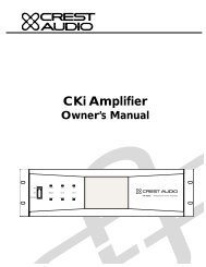
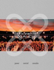
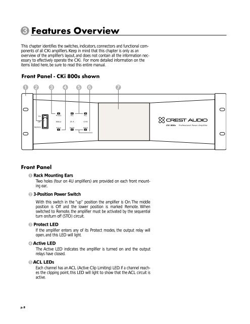
Front Panel - CKi 800s shown<br />
1 2 3 4 5 6 7<br />
��<br />
���<br />
������<br />
Front Panel<br />
�������<br />
���<br />
������ ����<br />
����<br />
������ ������<br />
1 Rack Mounting Ears<br />
Two holes (four on 4U amplifiers) are provided on each front mounting<br />
ear..<br />
2 3-Position Power Switch<br />
���<br />
������<br />
With this switch in the “up” position the amplifier is On.The middle<br />
position is Off and the lower position is marked Remote. When<br />
switched to Remote, the amplifier must be activated by the sequential<br />
turn on/turn off (STO) circuit.<br />
3 Protect LED<br />
If the amplifier enters any of its Protect modes, the output relay will<br />
open, and this LED will light.<br />
4Active LED<br />
The Active LED indicates the amplifier is turned on and the output<br />
relays have closed.<br />
5ACL LEDs<br />
Each channel has an ACL (Active Clip Limiting) LED. If a channel reaches<br />
the clipping point, this LED will light to show that the ACL circuit is<br />
active.<br />
����������������������������������������