Nexsys Modules - Crest Audio
Nexsys Modules - Crest Audio
Nexsys Modules - Crest Audio

You also want an ePaper? Increase the reach of your titles
YUMPU automatically turns print PDFs into web optimized ePapers that Google loves.
Gain Select Switch<br />
The 3-position gain select switch on the rear panel to sets the overall gain of<br />
the amplifier.The left and right switch positions set the amplifier for constant<br />
gain of x20 (26 dB) or x40 (32 dB) respectively.The center position sets the<br />
amplifier for constant sensitivity. In this position, a 0dBu (0.775 VRMS) input<br />
signal will produce maximum power at the amplifier’s output.The standard<br />
factory setting is for x40 (32dB).The specifications for a specific CKi models<br />
in Appendix A contain more gain/sensitivity information.<br />
Signal Ground Lift Switch<br />
The signal source equipment should share the same AC ground as the amplifier(s).<br />
In some cases, however, particularly if an amplifier is being installed in<br />
an existing system, this may result in a ground loop, creating excessive 60Hz<br />
hum at the amplifier’s output. If this happens, slide the ground lift switch on<br />
the amplifier’s rear panel to the “open” (left) position. In this position, the signal<br />
ground is lifted from the chassis ground and is clamped to ± 0.6V. Do not<br />
lift the ground if the amplifier and the signal source equipment are not on the<br />
same AC ground! In a properly designed system, the amplifier should receive<br />
its ground from the AC line cord to ensure safety and minimize noise.<br />
Sequential Turn On/Off (STO)<br />
CKi amplifiers come standard with Sequential Turn-On/Turn-Off (STO) circuitry.When<br />
the amplifier front power switch is set to “remote,” a single<br />
SPDT toggle switch or two SPST momentary switches can be used to turn<br />
the amplifier on and off. Using the same switch(es), additional amplifiers can<br />
be turned on/off sequentially by daisy chaining the STO "Out" terminals of<br />
one amplifier to the STO "In" terminals of a subsequent amplifier.The standard<br />
turn-on delay time between amplifiers is approximately 100ms; turn-off<br />
delay time is 200ms. When using NexSys control with an amplifier equipped<br />
with an NxEthernet or NxCobraNet module, these standard turn-on and<br />
turn-off delay times may be modified in the control software.<br />
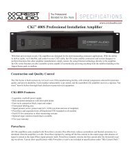
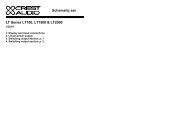
Standard Sequential Turn-On/Turn-Off Wiring<br />
For non-NexSys remote turn-on, a single SPDT toggle switch or two SPST<br />
momentary switches can be used. In either case, the switch(es) are wired to<br />
the “STO In” connector on the amplifier’s rear panel and the amplifier’s front<br />
panel power switch must be set to “Remote.” The switch(es) should be wired<br />
to close a connection between “Com” and “On” pins for turn-on, and<br />
between the “Com” and “Off” pins for turn-off. The diagram below illustrates<br />
the circuit:<br />
On<br />
Off<br />
������ ������<br />
������������������<br />
������������������<br />
�� �� ��� ���<br />
���� ����<br />
����� �����<br />
�� ��<br />
��� ���<br />
��� ���<br />
�� ��<br />
��� ���<br />
��� ���<br />
���� ����<br />
����� �����<br />
��� ���<br />
��� ���<br />
��� ���<br />
��� ���<br />
�� ��<br />
��� ���<br />
+ +<br />
�����������������������<br />
�����������������������<br />
Operation 5<br />
���<br />
�������<br />
���<br />
����<br />
���<br />
The shield on a balanced<br />
input line should<br />
be grounded at one end<br />
only (usually the sending<br />
end), and it must never<br />
be relied on to supply<br />
AC ground to the amplifier.<br />
When using NexSys<br />
control, hardwiring<br />
for manual switch<br />
closure between amplifiers<br />
should be used cautiously.<br />
If the switch closure<br />
output is wired up,<br />
it WILL cause the next<br />
amp to switch, regardless<br />
of which source<br />
(hardware switch or<br />
NexSys STO command)<br />
has initiated the command.<br />
a<br />
+<br />
p.19