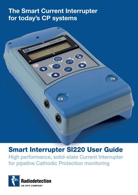
Smart Interrupter SI220 User Guide
Smart Interrupter SI220 User Guide
Smart Interrupter SI220 User Guide

Create successful ePaper yourself
Turn your PDF publications into a flip-book with our unique Google optimized e-Paper software.
The <strong>Smart</strong> Current <strong>Interrupter</strong><br />
for today’s CP systems<br />
<strong>Smart</strong> <strong>Interrupter</strong> <strong>SI220</strong> <strong>User</strong> <strong>Guide</strong><br />
High performance, solid-state Current <strong>Interrupter</strong><br />
for pipeline Cathodic Protection monitoring
<strong>Smart</strong> <strong>Interrupter</strong> – <strong>SI220</strong> <strong>User</strong> <strong>Guide</strong><br />
The <strong>Smart</strong> <strong>Interrupter</strong> provides a means of placing a<br />
characteristic signature on pipes by interrupting the flow<br />
of current in a Cathodic Protection System (CPS).<br />
The <strong>Smart</strong> <strong>Interrupter</strong> is specifically designed for use<br />
with the Radiodetection Stray Current Mapper (SCM) and<br />
Precision Pipeline Locator (PPL) and can also be used<br />
as a stand-alone interrupter with third party data loggers<br />
that measure and record CPS potentials.<br />
Multiple units can be synchronized to monitor more<br />
complex CPS networks.<br />
Configurations<br />
Technical Specification <strong>SI220</strong>-0 + 100A Booster<br />
<strong>User</strong> Controls – keypad<br />
Power On/Off<br />
Selects secondary functions on each key.<br />
See below.<br />
Select/ Previous / Next<br />
Changes a field, adjusts a time or changes<br />
a selection and selects individual SCM<br />
signals or PPL signal.<br />
2nd function: Selects previous and next<br />
waveforms.<br />
SI22V-0 (base unit)<br />
220V peak base unit (drives<br />
separate booster)<br />
10/SN2786-BP<br />
SI Booster unit<br />
100A output switcher (requires<br />
control unit <strong>SI220</strong>-0)<br />
10/SN2900<br />
Pulse mode<br />
Selects pulse mode. Sets on and off<br />
pulsing periods (e.g. ON = 3 seconds,<br />
OFF = 8 seconds). This enables signal<br />
identification when using more than<br />
one <strong>Smart</strong> <strong>Interrupter</strong> simultaneously<br />
to monitor complex networks.<br />
REVERSE POLARITY WARNING LED<br />
2nd function: Invert on/off waveform<br />
(e.g. Start ON to Start OFF).<br />
OK<br />
Confirms all selections.<br />
Stop/Start<br />
Stops and starts the <strong>Smart</strong> <strong>Interrupter</strong><br />
switching cycles.<br />
Accessories<br />
Bag (included). Crocodile clips (optional) 09/SN2786Z10. Auxiliary power<br />
connection leads 09/SN2786Z12.<br />
External connections<br />
The diagrams below shows the external connections to the <strong>Smart</strong> <strong>Interrupter</strong>.<br />
GPS ANTENNA<br />
CONNECTION<br />
BOOSTER PACK<br />
CONNECTION<br />
Clock<br />
Timer function allows activation and<br />
deactivation of the <strong>Smart</strong> <strong>Interrupter</strong> at<br />
defined times of the day (e.g. activate at<br />
7 am and deactivate at 5 pm, every day<br />
until you disconnect the <strong>Smart</strong> <strong>Interrupter</strong><br />
or you change the timings).<br />
2nd function: selects factory reset<br />
(clears settings).<br />
AUXILIARY POWER<br />
CONNECTIONS<br />
SCM<br />
Selects Stray Current Mapper (SCM) and<br />
Precision Pipeline Locator (PPL) signals.<br />
2nd function: selects display contrast.
<strong>Smart</strong> <strong>Interrupter</strong> – <strong>SI220</strong> <strong>User</strong> <strong>Guide</strong><br />
Display Icons<br />
The <strong>SI220</strong> has a 2 x 16 LCD display. Operating icons are shown in the first 5<br />
positions on the second line as indicated below:<br />
1 2 3 4 5<br />
1. Battery state/External power<br />
2. GPS icons<br />
3. Synchronization icons<br />
4. Timer<br />
5. Over-temperature and Booster connected<br />
Related Products<br />
Stray Current Mapper<br />
Stray currents can degrade the performance of Cathodic Protection<br />
Systems. These are typically caused by other cathodic protection systems,<br />
and dc electrified transport systems. They may be intermittent and difficult<br />
to identify.<br />
The display icons have the following<br />
meanings:<br />
Battery state/External power<br />
Full Low Empty External<br />
Power<br />
GPS Icons<br />
GPS Standby GPS Searching Antenna<br />
Fault (Flash)<br />
Position (steady)<br />
The Stray Current Mapper (SCM) system is a safe and cost effective<br />
method of undertaking stray current surveys on pipelines. It can be used to<br />
completely map the distribution of any current source accurately pinpointing<br />
problem areas.<br />
Min signal strength Max<br />
Synchronization Icons<br />
Sync Being Sync to GPS No Sync to GPS<br />
Determined OK Last Time Last Time<br />
‘Free Running’<br />
Timer<br />
Timer Activity<br />
Precision Pipeline Locator<br />
Mis-location of services results in significant and costly damage to pipelines.<br />
The PPL uses low frequency signaling technology to provide a precision<br />
location and depth of these pipelines from the surface without the need to<br />
dig potholes or penetrate the ground.<br />
Over-temperature and Booster connected<br />
Over Temp Tell-tale<br />
Booster Attached
<strong>Smart</strong> <strong>Interrupter</strong> – <strong>SI220</strong> <strong>User</strong> <strong>Guide</strong><br />
Connecting the <strong>Smart</strong> <strong>Interrupter</strong><br />
1. <strong>SI220</strong> (interrupting connection to structure)<br />
This is the preferred connection method. With this connection, an optional<br />
external supply can be used to extend the battery life of the <strong>Interrupter</strong>.<br />
The diagrams show connections for the <strong>SI220</strong>.<br />
CAUTION<br />
The <strong>Smart</strong> <strong>Interrupter</strong> must only be used by suitably trained personnel.<br />
Some modern CP systems have serial smoothing inductors (efficiency filters).<br />
It is imperative that the CP system is capable of being repeatedly interrupted<br />
without creating over-voltage or dangerous conditions.<br />
Always ensure that the CP system is suitably disconnected and de-energized<br />
before connecting and disconnecting the <strong>Smart</strong> <strong>Interrupter</strong> or Booster unit.<br />
Before connecting the <strong>Smart</strong> <strong>Interrupter</strong> or Booster unit to the CP supply,<br />
measure the maximum open-circuit CP voltage. Ensure that this voltage is<br />
below the <strong>Interrupter</strong>’s maximum RMS limit (155V) before connecting it. Peak<br />
voltages: Direct current 220V DC, half wave rectified AC 155V AC (average<br />
or RMS).<br />
Connection to CP voltages in excess of these limits may cause damage to<br />
the <strong>Smart</strong> <strong>Interrupter</strong> and Booster pack. Switching currents in excess of the<br />
above ratings can damage the <strong>Smart</strong> <strong>Interrupter</strong> and Booster pack.<br />
Always connect the <strong>Smart</strong> <strong>Interrupter</strong> and Booster unit before switching it<br />
on. Then switch on the CP system. If the <strong>Smart</strong> <strong>Interrupter</strong> is connected in<br />
reverse polarity a red LED lights on the Booster. Switch off the CP system<br />
and correct the connections.<br />
Ensure that the operating temperature is within the range -14°F (-20°C) to<br />
140°F (60°C).<br />
The <strong>SI220</strong> can be powered by an external power supply. When connecting<br />
the external supply lead, always connect it to the anode wire before plugging<br />
it into the <strong>Smart</strong> <strong>Interrupter</strong>. When disconnecting the external supply lead,<br />
always remove it from the <strong>Smart</strong> <strong>Interrupter</strong> before disconnecting it from the<br />
anode wire.<br />
Note that the <strong>Smart</strong> <strong>Interrupter</strong> base units and booster are environmentally<br />
rated to IP65 – If the units are to be deployed where there is likelihood of<br />
heavy rain storms then suitable covering must be supplied.<br />
Ensure adequate air-flow across the heat-sink.<br />
To prevent unauthorized access keep the <strong>Smart</strong> <strong>Interrupter</strong> secure if it is left<br />
unattended when in use.<br />
2. <strong>SI220</strong> (interrupting connection to anode)<br />
Where a connection to the structure is not possible this connection can<br />
be used.<br />
The Booster pack is driven by the <strong>SI220</strong> base unit to enable switching of<br />
currents up to 100A. Connect the booster pack to the base unit as shown.<br />
When connecting the Booster pack to either the anode cable or to the<br />
structure cable, ensure that the positive clip (marked with a red band) is<br />
connected to the most positive connection point and the negative clip<br />
(no red band) is connected to the most negative connection point. If the<br />
Booster pack is connected the wrong way round, the warning LED will light.<br />
Note: Leaving the <strong>Smart</strong> <strong>Interrupter</strong> or Booster pack reverse connected will<br />
damage these units.<br />
The <strong>SI220</strong> indicates that the booster pack is connected<br />
with the following icon:<br />
Booster pack connected<br />
Note that the <strong>SI220</strong> Booster pack is a heavy item<br />
(15kg) and should only be carried using the handle<br />
for short periods of time as a means of positioning<br />
the unit during installation or removal. Also note that<br />
after prolonged use the unit could be 10°C hotter<br />
than ambient. Therefore exercise caution when lifting<br />
Please inspect the units and cable forms for damage<br />
before using. If the cable forms or the unit show<br />
signs of damage, do not use.<br />
Do not carry the base unit or booster pack by any of<br />
the test leads or connection cableforms.
<strong>Smart</strong> <strong>Interrupter</strong> – <strong>SI220</strong> <strong>User</strong> <strong>Guide</strong><br />
Operating the <strong>Smart</strong> <strong>Interrupter</strong><br />
Inverting pulse switching<br />
It is possible to invert the switching order of the pulse mode patterns (this<br />
feature only works in pulse mode). This is useful for dataloggers that require<br />
the CP potentials to be in a specific order. The normal mode of operation is<br />
to switch the CP ON, then OFF.<br />
Press the Power ON/OFF button<br />
The first screen is displayed for approximately 2 seconds, after which time<br />
the second screen is displayed, this being the last mode used.<br />
e.g. start-up screen<br />
e.g. H/W start-up <strong>SI220</strong>-0 screen GPS<br />
S/W Ver 1.3000<br />
e.g. second screen (< > indicated parameter selected for change)<br />
Stopped On<br />
Off=1.2s<br />
Pulse Mode<br />
In pulse mode the <strong>Smart</strong> <strong>Interrupter</strong> puts a simple ON/OFF pulse onto<br />
the line and enables signal identification when using more than one <strong>Smart</strong><br />
<strong>Interrupter</strong> at the same time. If using more than one <strong>Smart</strong> <strong>Interrupter</strong> and<br />
there is a need to identify each individually then it is necessary to make the<br />
pulse ON/OFF times different for each unit.<br />
Press the pulse mode button to select pulse mode. The<br />
following screen is displayed with the ON time highlighted by<br />
. Press the OK button to toggle between ON time and<br />
OFF time.<br />
Stopped On<br />
Off=1.2s<br />
To make the unit switch the voltage OFF and then<br />
ON: Hold the shift key and press pulse invert key.<br />
The display will toggle the ON and OFF times as shown below. To revert to<br />
the previous switching mode, repeat the key press sequence. The order of<br />
switching (ON-OFF or OFF-ON) is stored with the pulse pattern and will be<br />
recalled if using the previous mode recall feature.<br />
Running Off=2.5s<br />
On<br />
Previous settings<br />
Settings are stored when the Stop/Start button is pressed. The last 9<br />
patterns are stored in the order used.<br />
To set the ON time, press the left/<br />
right buttons until the desired time is<br />
displayed and press OK. The OFF time is<br />
now highlighted .<br />
Stopped On=1.0s<br />
Off<br />
To retrieve any one of the last ten settings in pulse mode, press and hold<br />
the shift key and press and release the recall key.<br />
To set the OFF’ time, press the left/<br />
right buttons until the desired time<br />
is displayed.<br />
Stopped On<br />
Off=2.5s<br />
Note: From 0 to 10 seconds the time increases in steps of 0.1 seconds.<br />
From 10 to 100 seconds the time increases in steps of 1 second. Times<br />
can be changed with the <strong>Smart</strong> <strong>Interrupter</strong> running or stopped.<br />
Once you have set the On and Off times press the Stop/Start<br />
button to start the <strong>Smart</strong> <strong>Interrupter</strong> running and apply the<br />
signal to the pipe.<br />
Running On<br />
Off=2.5s<br />
The <strong>Smart</strong> <strong>Interrupter</strong> is now switching (Interrupting) the CPS.<br />
Left and Right keys then step through the patterns. Press OK to select<br />
the required pattern.<br />
This times out if nothing is selected, returning to previous screen above.<br />
Prev On=1.0s<br />
Off=2.5s<br />
Patterns are numbered 0 to 9 with 9 being the most recent.<br />
Synchronizing <strong>Smart</strong> <strong>Interrupter</strong>s<br />
Multiple <strong>SI220</strong> units can be synchronized via the inbuilt GPS timer function.<br />
This enables the effects of more complex pipeline protection systems<br />
incorporating multiple Cathodic Protection Systems to be evaluated.<br />
The units will be synchronized and will stay in synchronization as long<br />
as the <strong>SI220</strong> antennae are connected and receiving satellite information<br />
(a clear view of the sky is required).<br />
Note: If the unit has not been used for some time (over 4 weeks) it may<br />
take several minutes for the <strong>Smart</strong> <strong>Interrupter</strong> to obtain a GPS signal.<br />
This is normal and does not require any user action.
<strong>Smart</strong> <strong>Interrupter</strong> – <strong>SI220</strong> <strong>User</strong> <strong>Guide</strong><br />
GPS operating symbols are:<br />
GPS standby – GPS asleep (no action required)<br />
GPS searching<br />
Press the left/right buttons to change the set time (local time) in 30 minute<br />
intervals. Press OK to toggle from start time to stop time. Once the start/stop<br />
times have been set press OK to display the Local Time Now screen.<br />
Antenna fault (flashing symbol) – connect or replace antenna<br />
Antenna position (steady symbol) – move <strong>Smart</strong> <strong>Interrupter</strong><br />
antenna to a better GPS reception area<br />
Signal level – Minimum signal strength to Maximum<br />
signal strength<br />
Press the left/right arrows to adjust the current time in steps of 1 hour this<br />
allows for adjustment due to time zone (and daylight saving, for example).<br />
Press OK. The screen reverts to the previous mode with the addition of<br />
the flashing timer symbol. The run/stop button is disabled as the timer<br />
now has control.<br />
Timer active<br />
Synchronization with the GPS takes<br />
place every 30 minutes; symbols are:<br />
Synchronization being determined<br />
Synchronization to GPS OK last time<br />
Running On<br />
Off=2.5s<br />
When the start time is reached the screen shows the unit running as normal<br />
and the timer icon flashes to show that the timer is operating. When the stop<br />
time is reached the display shows stopped.<br />
Note: In Timer mode, Stop/Start has no effect; all other functions are<br />
operational.<br />
To cancel Timer mode:<br />
No synchronization to GPS last time (“free running”)<br />
Press the Timer button. The Use Timer screen is displayed.<br />
Using Timers<br />
The <strong>Smart</strong> <strong>Interrupter</strong> clock is automatically adjusted every time a GPS signal<br />
is received. The clock automatically adjusts to local time zone (without any<br />
daylight saving offsets which can be set manually, see below).<br />
You can instruct a <strong>Smart</strong> <strong>Interrupter</strong> to activate at a certain time and<br />
deactivate at another.<br />
Press the Timer button. The Use Timer screen is displayed.<br />
Use Timer <br />
Press the left/right arrow buttons to select No. Press OK to select NO and<br />
the main screen is displayed. Timer is now inactive. Timer icon disappears.<br />
Stopped On<br />
Off=2.5s<br />
Use Timer <br />
Press the left/right arrow buttons to select either Yes or No. If you select No<br />
the unit reverts to the main screen and the timer will not operate. Press OK<br />
to select YES and the timer screen is displayed. See Setting the timer.<br />
If there is no GPS signal or the GPS antenna is not connected, the timer<br />
cannot be enabled and the following screen is displayed.<br />
Use Timer <br />
No GPS Time Yet<br />
Press OK to return to the previous screen without setting the timer.<br />
Setting the timer<br />
If GPS sync is achieved, the <strong>Smart</strong> <strong>Interrupter</strong> is ready to be set up. Set the<br />
start and stop time in local time and set the GPS to the Local Time.<br />
Start <br />
Stop 01:00pm
<strong>Smart</strong> <strong>Interrupter</strong> – <strong>SI220</strong> <strong>User</strong> <strong>Guide</strong><br />
<strong>Smart</strong> <strong>Interrupter</strong> with SCM and PPL<br />
Stray currents are particularly damaging to buried metallic pipework as they<br />
can lead to accelerated and invisible corrosion. The Stray Current Mapper<br />
(SCM) allows the corrosion technician to identify these problems.<br />
The <strong>SI220</strong> will provide any one of four unique SCM signals in order to enable<br />
the Stray Current Mapper to separately identify the effects of different CPS<br />
elements in a protection network.<br />
<strong>Smart</strong> <strong>Interrupter</strong> Maintenance<br />
The <strong>Smart</strong> <strong>Interrupter</strong> is powered by 2xLR20, D-cell batteries<br />
Battery level indication. When the battery level is full<br />
the battery symbol remains black. When the battery<br />
level becomes low the battery icon shows a single<br />
bar. When there is no bar replace the batteries.<br />
The Precision Pipeline Locator is used to precisely locate and measure<br />
the depth in difficult situations. The <strong>SI220</strong> will generate a PPL signal<br />
to enable this.<br />
SCM and PPL Modes<br />
Press SCM; the following screen is displayed:<br />
Stopped SCM <br />
The four selectable SCM output signals are numbered 0-3. The PPL signal is<br />
designated PPL 1.<br />
Press the right or left arrow to cycle through the signals. If using several<br />
<strong>Smart</strong> <strong>Interrupter</strong>s, ensure that each has a different signal selected. For PPL,<br />
press the right or left button to cycle through the waveforms until PPL 1<br />
is displayed.<br />
Stopped SCM <br />
External Power<br />
The <strong>SI220</strong> can be powered by taking power from the CPS. When<br />
using the external power supply the battery level indicator is<br />
replaced by the external power icon.<br />
Isolate CP supply before connecting auxiliary power<br />
to <strong>SI220</strong><br />
Press the Stop/Start button to start the <strong>Smart</strong> <strong>Interrupter</strong> and apply the<br />
signal to the pipe. The Running SCM or PPL screen is displayed<br />
as appropriate.<br />
Running SCM <br />
Factory reset<br />
To set <strong>Smart</strong> <strong>Interrupter</strong> to default settings clearing stored patterns.<br />
Setting display contrast<br />
Contrast <br />
Press shift and contrast button. The contrast<br />
screen is displayed.<br />
Reset Unit? <br />
BB Version 1.000<br />
Press shift and set-up button. The reset screen<br />
is displayed.<br />
To reset select yes. Press OK. Confirmation is requested; press Ok to reset.<br />
Selecting No using the arrow keys to toggle and pressing OK returns the<br />
unit unchanged to the previous screen.<br />
Press the left and right buttons to select the desired contrast level. Settings<br />
are from 1 (lightest) to 20 (darkest). Press Ok to select.<br />
Temperature warning<br />
The <strong>Smart</strong> <strong>Interrupter</strong> and <strong>Smart</strong> <strong>Interrupter</strong>/Booster pairing have hardware<br />
and software over-temperature protection.<br />
If the <strong>Smart</strong> <strong>Interrupter</strong> and Booster are used at higher currents (which is<br />
made worse by high ambient temperatures), the unit can overheat. Under<br />
these conditions the unit stops switching (current no longer interrupted)<br />
and the over temperature warning screen is displayed.<br />
Over Temperature<br />
Please Wait<br />
This screen is maintained and all buttons other than power are disabled until<br />
the thermal cut-out resets. Once the thermal cut-out has reset the <strong>Smart</strong><br />
<strong>Interrupter</strong> resumes normal operation in stopped mode. An over-temperature<br />
event is flagged by the OT! Icon, indicating that an Over Temperature event<br />
has occurred.<br />
<strong>Smart</strong> <strong>Interrupter</strong> Functional Check<br />
To check the switching function:<br />
Switch off the <strong>Smart</strong> <strong>Interrupter</strong> and disconnect it from the CP supply.<br />
Connect a DMM set to measure the resistance (in diode mode) between<br />
the output leads, meter +ve to the Red marked lead and meter -ve to the<br />
Black lead.<br />
With the unit off, the resistance measured should be greater than 100kΩ.<br />
Switch the <strong>Smart</strong> <strong>Interrupter</strong> On and set it to Stopped.<br />
The resistance measured should now be very much less than 10Ω.<br />
Reverse the connections and check that the red LED on the Booster pack<br />
illuminates. Note: The resistance readings may be erroneous.<br />
Switch the <strong>Smart</strong> <strong>Interrupter</strong> Off and disconnect the meter.<br />
Note: If the unit is set to Running, the resistance value will fluctuate<br />
between these readings as the switch turns On and Off. If either resistance<br />
measurement is outside the limits stated above, the unit should be returned<br />
to Radiodetection Ltd. for service.<br />
Over temperature event flagged
<strong>SI220</strong> Technical Specification<br />
■<br />
■<br />
■<br />
■<br />
■<br />
■<br />
■<br />
■<br />
■<br />
■<br />
■<br />
■<br />
Switching capacity: Max Switching Current = 100A<br />
Max Switching Voltage = 220Vpeak / 155Vrms<br />
Rated Impulse Voltage = 1500V<br />
Supply: Requires 2 x 1.5V Alkaline D Cells, Duracell LR20/D<br />
(or equivalent)<br />
Battery Life: 300 hours @20 degrees C (Battery life can be<br />
extended, Auxiliary power from the CP system via 4mm shrouded<br />
sockets on the side of the base unit, if above 5V open circuit)<br />
Auxiliary (optional) Supply:<br />
Min Aux Voltage = 5Vrms<br />
Max Aux Voltage = 220Vpeak / 155Vrms<br />
Protection: Class II double insulated. Thermal (software and<br />
hardware) and over voltage protection. Over current protection<br />
via thermal switches. Lightning related surge and spike<br />
Connection Outputs: 2 cables (CP Auxiliary power, CP<br />
switched) Customer lugs (Crocodile clips as option)<br />
Switching Patterns: On/Off Time 0-100s (0.1sec increments to<br />
10secs) Unit saves history of last ten patterns. Last pattern used<br />
selected at power on. SCM and Precision Pipe Locator signals<br />
Synchronization: via GPS synchronization (as standard):<br />
+/- 4ms<br />
24hr Timer: Programmable On/Off timer repeats every 24hrs<br />
Microcontroller: Controls keyboard inputs, LCD functions,<br />
non-volatile storage, USB I/O and FET switching<br />
<strong>User</strong> Interface: 2 line by 16 character LCD, alpha numeric<br />
and special character display. Automatic backlight<br />
Keypad: <strong>User</strong> input via 9 key membrane keypad<br />
■ Software Upgrades: Via USB interface<br />
■ Dimensions & weight (base unit): Size 12” (300mm) x 6”<br />
(150mm) x 3” (80mm), Weight 2.5kg (5.5lb)<br />
■ Dimensions & weight (booster unit): 10” (255mm) x 10”<br />
(255mm) x 9.6” (216mm), Weight 13.3kg (29lb)<br />
■ Environmental Protection: IP65 rain and dust resistant. Note that<br />
if the unit is to be used in heavy storm conditions then it should be<br />
suitably covered<br />
■ Ambient Operating Temperature: -14°F (-20°C) to 140°F (60°C)<br />
■ Reverse Polarity: Indication of reverse polarity via a red LED on<br />
Booster pack<br />
■ Construction: Housing high impact plastic. Fire retardant<br />
■ Compliance:<br />
FCC Part CFR Part 15* EN61326-1: 2006<br />
UL61010-1: 2004 EN61010-1: 2001<br />
■ Lead sets: Switching leads. Copper tube lugs. Crocodile clips as<br />
optional accessory<br />
■ Advanced features: The <strong>Smart</strong> <strong>Interrupter</strong> provides switching<br />
patterns compatible with Radiodetection’s Stray Current Mapper<br />
(SCM) and Precision Pipe Locator (PPL) products and PCM/A-<br />
Frame for ACVG surveys<br />
*NOTE: This equipment has been tested and found to comply with the limits<br />
for a Class A digital device, pursuant to Part 15 of the FCC Rules. These limits<br />
are designed to provide reasonable protection against harmful interference<br />
when the equipment is operated in a commercial environment. This equipment<br />
generates, uses, and can radiate radio frequency energy and, if not installed<br />
and used in accordance with the instruction manual, may cause harmful<br />
interference to radio communications. Operation of this equipment in a<br />
residential area is likely to cause harmful interference in which case the user<br />
will be required to correct the interference at his own expense.<br />
Changes or modifications not expressly approved by the party responsible<br />
for compliance could void the user’s authority to operate the equipment.<br />
America<br />
Radiodetection<br />
154 Portland Road<br />
Bridgton, ME 04009, USA<br />
Tel: +1 (207) 647 9495<br />
Toll Free: +1 (877) 247 3797<br />
Fax: +1 (207) 647 9496<br />
Email: rd.sales.us@spx.com<br />
Web: www.radiodetection.com<br />
Pearpoint<br />
72055 Corporate Way<br />
Thousand Palms CA 92276, USA<br />
Tel: +1 800 688 8094<br />
Tel: +1 760 343 7350<br />
Fax: +1 760 343 7351<br />
Email: pearpoint.sales.us@spx.com<br />
Web: www.radiodetection.com<br />
Radiodetection (Canada)<br />
344 Edgeley Boulevard, Unit 34<br />
Concord, Ontario L4K 4B7, Canada<br />
Tel: +1 (905) 660 9995<br />
Toll Free: +1 (800) 665 7953<br />
Fax: +1 (905) 660 9579<br />
Email: rd.sales.ca@spx.com<br />
Web: www.radiodetection.com<br />
To see the full range of products and<br />
services provided by Radiodetection visit:<br />
www.radiodetection.com<br />
Europe<br />
Radiodetection Ltd (UK)<br />
Western Drive<br />
Bristol BS14 0AF, UK<br />
Tel: +44 (0) 117 976 7776<br />
Fax: +44 (0) 117 976 7775<br />
Email: rd.sales.uk@spx.com<br />
Web: www.radiodetection.com<br />
Radiodetection (France)<br />
13 Grande Rue, 76220<br />
Neuf Marché, France<br />
Tel: +33 (0) 232 8993 60<br />
Fax: +33 (0) 235 9095 58<br />
Email: rd.sales.fr@spx.com<br />
Web: http://fr.radiodetection.com<br />
Radiodetection (Benelux)<br />
Industriestraat 11<br />
7041 GD ’s-Heerenberg, Netherlands<br />
Tel: +31 (0) 314 66 47 00<br />
Fax: +31 (0) 314 66 41 30<br />
Email: rd.sales.nl@spx.com<br />
Web: http://nl.radiodetection.com<br />
Radiodetection (Germany)<br />
Groendahlscher Weg 118<br />
46446 Emmerich am Rhein, Germany<br />
Tel: +49 (0) 28 51 92 37 20<br />
Fax: +49 (0) 28 51 92 37 520<br />
Email: rd.sales.de@spx.com<br />
Web: http://de.radiodetection.com<br />
Service and Maintenance<br />
The <strong>SI220</strong> is designed so that it does not require regular calibration. However, as with all test equipment, it is recommended that it is<br />
serviced at least once a year either at Radiodetection or an approved repair centre.<br />
Radiodetection products are under continuous development and are subject to change, we reserve the right to alter or amend any published<br />
specification without notice.<br />
Copyright 2008 Radiodetection Ltd. - SPX Corporation. All rights reserved. Radiodetection Ltd. is a subsidiary of SPX Corporation.<br />
Asia-Pacific<br />
Radiodetection (Asia-Pacific)<br />
Room 708, CC Wu Building<br />
302-308 Hennessy Road, Wan Chai<br />
Hong Kong SAR, China<br />
Tel: +852 2110 8160<br />
Fax: +852 2110 9681<br />
Email: rd.sales.cn@spx.com<br />
Web: www.radiodetection.com<br />
Radiodetection (China)<br />
Hongfu Mansion, Room 61622<br />
Zheng Ge Zhuang, Bei Qi Jia Town<br />
Chang Ping District<br />
Beijing 102209, China<br />
Tel: +86 (0) 10 8975 5540<br />
Fax: +86 (0) 10 8975 5640<br />
Email: rd.service.cn@spx.com<br />
Web: http://cn.radiodetection.com<br />
Radiodetection (Australia)<br />
Unit 14, 5-7 Prosperity Parade<br />
Warriewood NSW 2102, Australia<br />
Tel: +61 (0) 2 9979 8555<br />
Fax: +61 (0) 2 9979 7733<br />
Email: rd.sales.au@spx.com<br />
Web: www.radiodetection.com<br />
90/UG071-ENG/03