Vantage 2200 Brochure - Eastech Flow Controls
Vantage 2200 Brochure - Eastech Flow Controls
Vantage 2200 Brochure - Eastech Flow Controls
You also want an ePaper? Increase the reach of your titles
YUMPU automatically turns print PDFs into web optimized ePapers that Google loves.
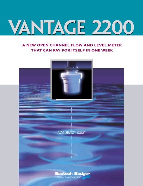
<strong>Vantage</strong> ® <strong>2200</strong><br />
A NEW OPEN CHANNEL FLOW AND LEVEL METER<br />
THAT CAN PAY FOR ITSELF IN ONE WEEK<br />
ACCURACY 0.02”<br />
<strong>Eastech</strong> Badger<br />
ULTRASONIC FLOW MEASUREMENT
<strong>Vantage</strong> ® <strong>2200</strong><br />
EASTECH BADGER COMBINES FLOW MEASUREMENT, LEVEL TRANSMISSION AND<br />
DATA LOGGING WITH IEEE 754 PRECISION ACCURACY AND 5 MINUTE PROGRAMMING.<br />
The <strong>Vantage</strong> <strong>2200</strong> is an advanced microprocessor-based ultrasonic transmitter utilized for extremely accurate<br />
measurement of both liquid level and flow in open channels. Each unit is equipped with an internal data logger<br />
that provides for on-screen display of maximum, minimum and average daily flows. More than 70 standard<br />
flow equations for flumes, weirs and open flow nozzles are stored in non-volatile memory. Dual sensors can be<br />
input to a single set of electronics for dual weir/flume or bar screen level applications. The <strong>Vantage</strong> <strong>2200</strong> is<br />
designed to be extremely user-friendly with an easy to read 20 character alphanumeric, self-prompting display<br />
and a menu-driven programming guide available in English, Spanish and German.<br />
FLOW<br />
The <strong>Vantage</strong> <strong>2200</strong> is pre-programmed<br />
at the factory for specific customer<br />
applications. If on-site calibration is<br />
required, more than 70 standard flow<br />
equations for flumes, weirs and open flow nozzles are stored in<br />
non-volatile memory. For non-standard applications, a site specific<br />
H/Q table may be entered through the 16 button keypad.<br />
LEVEL<br />
When utilized strictly for level<br />
measurement, the <strong>Vantage</strong> <strong>2200</strong> will<br />
accurately measure fluid levels in<br />
ranges up to 50 feet. Initial programming<br />
is simply accomplished through self-prompting<br />
displays assisted by menu-driven programming guides.<br />
APPLICATIONS<br />
" Plant Influent<br />
" Plant Effluent<br />
" Dual Channel Measurement<br />
The FB2 and FB4 sensor heads are both<br />
capable of withstanding indefinite submersion.<br />
The transmitter portion of the <strong>2200</strong> is<br />
FM approved for Nema 4, 4X, Class I, Division<br />
2 nonincendive hazardous environments and<br />
is equipped as standard with an integrated data logger. <strong>Flow</strong><br />
data may be accessed through a comprehensive selection of<br />
electronic outputs: 4-20mA, programmable relays, RS232 / 485,<br />
Modbus ® , Profibus ® and DeviceNet ® .<br />
APPLICATIONS<br />
Level Measurement #<br />
Differential Level Measurement #<br />
Dual Channel Measurement #<br />
Pump Alternation #<br />
FM certified for hazardous service, sensing<br />
heads are available in Tefzel ® , PVC or glassfilled<br />
polyester epoxy and are accurate to<br />
within ±0.02 inches. Both the sensing and<br />
transmitter portion of the <strong>Vantage</strong> <strong>2200</strong> are<br />
warrantied for a period of 3 years. Each unit is equipped<br />
with gas discharge arrestors and EMI/RFI filtering to<br />
prevent failure due to lightning and power surges.
Accuracy 0.02“<br />
The Open Channel <strong>Flow</strong>meter<br />
that can pay for itself in one week<br />
The overall accuracy of an ultrasonic open channel flowmeter is dependent upon conversion of level measurement to<br />
flow. The more accurate the conversion, the more accurate the flow data. A 10% error in level measurement can result<br />
in a 25% error in flow measurement.<br />
Since the <strong>Vantage</strong> <strong>2200</strong> employs IEEE 754 single floating point precision in all of its computations, an<br />
error of less than 0.0000005% is introduced during the level to flow conversion.<br />
When billing customers for treatment services, the accuracy of the flow information obtained directly translates into<br />
dollars. Since level accuracy statements from most open channel flowmeter manufacturers will vary from .02” to .25”, it is<br />
extremely important to study these statements in order to determine the best suited product for the intended application.<br />
COMPARATIVE COST ANALYSIS (0.25” vs 0.02”)<br />
18” PARSHALL FLUME WITH 3” HEAD RISE<br />
Q = K x<br />
H<br />
FLOW COEFFICIENT FACTOR HEAD RISE (ft)<br />
(X) POWER FACTOR<br />
FLOWMETER Accuracy: 0.25 inches VANTAGE <strong>2200</strong> Accuracy: 0.02 inches<br />
Q = K x H (X)<br />
Q = 6 x 0.229 (1.538)<br />
Q = 0.6258 cu. ft./sec.<br />
Q = 281 GPM<br />
A Level Error of 0.25” (8.3%)<br />
Results in a 12.5% <strong>Flow</strong> Error<br />
Q = K x H (X)<br />
Q = 6 x 0.248 (1.538)<br />
Q = 0.7044 cu. ft./sec.<br />
Q = 316 GPM<br />
A Level Error of 0.02” (0.67%)<br />
Results in a 1.25% <strong>Flow</strong> Error<br />
At the national average billing rate of $2.61/1000 gal., an 11.25% (12.5% - 1.25%) flow error differential<br />
in a 1MGD plant translates to 112,500 gallons/day or 787,500 gallons/week of unbilled revenue<br />
($2,055/week) . The higher accuracy of the <strong>Vantage</strong> <strong>2200</strong> has the potential to pay for itself within the<br />
first week of operation while adding $106,880/year to the plant’s revenue stream.<br />
As can be seen from the tables below, a 10% error in level measurement can result in a 25% error in flow measurement.<br />
The tables also verify that a meter with an accuracy statement of 0.25 inches will not provide the needed accuracy for billing<br />
or NPDES permit requirements–especially when coupled with normally accepted flume and weir accuracies of 3 to 5%.<br />
18 Inch Parshall Flume<br />
Flume Accuracy 0.02 inches Accuracy 0.04 inches Accuracy 0.25 inches<br />
Head Rise Level Error <strong>Flow</strong> Error Level Error <strong>Flow</strong> Error Level Error <strong>Flow</strong> Error<br />
3 inches 0.67% 1.25% 1.3% 2.9% 8.3 % 12.5%<br />
6 inches 0.33% 0.54% 0.67% 1.0% 4.15% 6.26%<br />
9 inches 0.22% 0.35% 0.44% 0.69% 2.05% 4.16%<br />
60 Degree V-Notch Weir<br />
Weir Accuracy 0.02 inches Accuracy 0.04 inches Accuracy 0.25 inches<br />
Head Rise Level Error <strong>Flow</strong> Error Level Error <strong>Flow</strong> Error Level Error <strong>Flow</strong> Error<br />
2 inches 1.0% 3.59% 2.0% 5.19% 12.5% 32.8%<br />
4 inches 0.5% 1.25% 1.0% 2.5% 6.25% 15.6%<br />
8 inches 0.25% 0.64% 0.5% 1.28% 3.13% 7.66%
applications<br />
flow & level<br />
dual sensors<br />
Pump alternation<br />
The FM approved electronics of the <strong>2200</strong> is<br />
extremely versatile and can be programmed<br />
for flow (using weirs/flumes or any special<br />
H/Q function) or level measurement of up to<br />
50 feet. Three sensors are available. The FB2<br />
and FB4 sensors are capable of measuring<br />
flow or level from 0-25 feet. The FB3 is a<br />
glass-filled polyester sensor with an extended<br />
level range of 0-50 feet.<br />
FLOW<br />
The following is a partial list of the stored<br />
flow to primary element functions.<br />
" Parshall flumes<br />
" Manhole flumes<br />
" Palmer Bowlus flumes<br />
" Trapezoidal flumes<br />
" H flumes<br />
" V Notch weirs<br />
" Contracted weirs<br />
" Suppressed weirs<br />
" Cipoletti weirs<br />
" Open flow nozzles<br />
" Kennison nozzles<br />
" Mannings circular<br />
" Mannings rectangular<br />
" Special H/Q<br />
LEVEL<br />
Level measurement can be programmed in<br />
the <strong>2200</strong> for a range of 0-50 feet. Vertical<br />
rectangular and cylindrical or horizontal<br />
cylindrical vessels are typical applications.<br />
Dual sensors may be used with the <strong>Vantage</strong><br />
<strong>2200</strong> electronics. Individual display functions<br />
are provided for each sensor. This allows for<br />
two separate measurements within a single<br />
meter.<br />
Typical arrangements are:<br />
Dual Sensors<br />
Dual weirs or flumes or flow for flume/weir<br />
and level. Sensors may be programmed identically<br />
or with different calibration variables.<br />
Bar Screen Level Differential<br />
This will alert the operator to a clogged bar<br />
screen through the use of a specific alarm<br />
assigned to one of the relays. The difference<br />
between level 1 and level 2 will be displayed.<br />
Compound Weirs<br />
Programming dual sensors for a compound<br />
weir will allow for greater accuracy over the<br />
entire flow range.<br />
20<br />
19<br />
18<br />
17<br />
16<br />
15<br />
14<br />
13<br />
12<br />
11<br />
10<br />
9<br />
8<br />
7<br />
6<br />
5<br />
4<br />
3<br />
2<br />
1<br />
0<br />
Pump 3<br />
Pump 2<br />
Pump 1<br />
ON<br />
OFF<br />
ON<br />
OFF<br />
ON<br />
OFF<br />
The pump alternation feature of the <strong>Vantage</strong><br />
<strong>2200</strong> is utilized when the treatment facility<br />
has more than two pumps that are to be<br />
actuated based upon level set points.<br />
For example: a sewer line will feed into a<br />
wet well at a lift station. The station employs<br />
three pumps. The wet well is 20 feet deep. As<br />
the wet well fills, the operator wants to turn<br />
on the pump (Pump 1) when the level<br />
reaches 12 feet and off at 2 feet. If the level<br />
in the well continues to rise with only one<br />
pump running, the operator will probably<br />
require the second pump (Pump 2) to come<br />
on at a level of 16 feet and off at 8 feet. If<br />
the level in the well continues to rise with<br />
both pumps running, the operator will<br />
initiate a third pump (Pump 3) to come on<br />
at a level of 18 feet and off at 12 feet.<br />
There are three setpoints: on at 12 feet, off at<br />
2 feet (Setpoint A); on at 16 feet,off at 8 feet<br />
(Setpoint B); on at 18 feet,off at 12 feet (Setpoint<br />
C).<br />
With the pump alternation feature, the setpoints<br />
in the <strong>2200</strong> are not assigned to a specific<br />
relay controlling a specific pump. The<br />
<strong>2200</strong> tracks each time a relay is activated,<br />
and when a setpoint is reached, the relay<br />
with the least number of activations is<br />
tripped. WITH THIS FEATURE, ALL THREE<br />
PUMPS WILL EXPERIENCE EVEN WEAR.<br />
The pump alternation feature may also be<br />
employed on filling applications—such as a<br />
water tank fed by multiple pumps.<br />
Setpoint B<br />
Setpoint C<br />
Setpoint A
programming data logging information display<br />
04/05/2003 08:36.02<br />
Flw1 451 GPM<br />
LvL1 12.10 in<br />
1T 14x10 GAL<br />
04/05T 00x10<br />
F1 Avg 249.96 GPM<br />
Min 00 08:27<br />
Max 250.0 07:13<br />
04/05/2003 08:36.02<br />
Flw1 451 GPM<br />
LvL1 12.10 in<br />
1T 14x10 GAL<br />
Page 1<br />
5 Minute Field Programming<br />
The <strong>Vantage</strong> <strong>2200</strong> utilizes a self-prompting<br />
display that allows for 5 minute programming<br />
of standard applications and 15 minute<br />
programming of in-depth data logging<br />
applications and auxiliary outputs. The menu<br />
driven programming feature allows the user<br />
to read the display status, log values, and calibrate<br />
the <strong>2200</strong> with a drill down type menu<br />
structure in English, Spanish and German.<br />
Up to 78 primary element functions for weirs<br />
and flumes are stored by size and name with<br />
the added capability of entering special H/Q<br />
curves by flow (in engineering units). All<br />
flow calculations are displayed as actual<br />
primary elements, not as power function.<br />
Mounting dimensions for the sensor are<br />
displayed for each application.<br />
The microprocessor-based electronics can be<br />
programmed to allow customer selection of<br />
tank shape or flow functions. The following is<br />
standard: Parshall flume, Manhole TM flume,<br />
Lagco flume, V-Notch weir, open flow nozzle<br />
as well as Manning’s equation. Special flumes<br />
can be programmed in the field by following<br />
a simple setup procedure.<br />
A 16 button keypad drives the menu section.<br />
Outputs are 4-20 mA, 5 programmable<br />
relays, RS-232 serial port (allows for real-time<br />
communications operating in a Modbus ®<br />
protocol) and a separate RS-485 port.<br />
Profibus ® and DeviceNet ® communication<br />
protocols are also available.<br />
Flash memory is employed for logging flow<br />
data. Data is retrieved by viewing the local<br />
display or downloaded via the serial port.<br />
The <strong>Vantage</strong> <strong>2200</strong> has a 256K Byte logger<br />
with storage intervals. The logger can be<br />
programmed for various time intervals. Up<br />
to 8 channels can be logged, including flow,<br />
level setpoints, and totals for one or two<br />
sensors.<br />
Daily Averages<br />
Daily summary allows viewing of the previous<br />
eight days. This includes times, dates,<br />
averages, minimums, maximums and totals.<br />
Logger Graph<br />
In addition, a bar graph may be visually displayed<br />
on the <strong>2200</strong>. The graph will display<br />
the stored logger data in pre-programmed<br />
time intervals.<br />
04/05T 14:50-15:00<br />
Data Retrieval<br />
Logger data can be collected by using a laptop<br />
computer, an optional modem installed<br />
in the <strong>2200</strong> enclosure or by the Palm PDA<br />
data collection module (see page 6). The<br />
Palm III may be utilized for downloading of<br />
all data from the <strong>2200</strong> logger. Just purchase a<br />
standard Palm III and download free software<br />
from the <strong>Eastech</strong> Badger website (available<br />
9/01).<br />
Flw2 451 GPM<br />
LvL2 12.10 in<br />
2T 14x10 GAL<br />
Page 2<br />
The <strong>Vantage</strong> <strong>2200</strong> utilizes a 20 character<br />
four line backlit display. The main screen<br />
can be programmed to display up to<br />
eight lines of meter information such as<br />
flow 1 and/or flow 2 (for dual sensors),<br />
totals 1 and/or totals 2 (for dual sensors),<br />
level 1 and/or level 2 (for dual sensors),<br />
time, date and relay alarms. The order of<br />
display line information is programmed<br />
to user preference. The backlit display<br />
may be programmed to be ON or OFF,<br />
or to remain OFF during a selected time<br />
interval. Display contrast is fully<br />
adjustable.<br />
The <strong>2200</strong> will display proper mounting<br />
distances for all programmed primary<br />
devices. Diagnostic information is<br />
retrieved via a menu-driven self-test<br />
program capable of isolating fault<br />
parameters such as: loss of signal, 4-20<br />
mA loop failure, logger memory full,<br />
communications error, sensor fault and<br />
open transmitter cable connection.
data transfer<br />
MULTIPLE OUTPUTS<br />
The <strong>Vantage</strong> <strong>2200</strong> is designed for reliable and accurate retrieval of<br />
data—either on-site or remotely.The unit is equipped, as standard, with<br />
an integrated data logger capable of storing large amounts of information<br />
for later analysis. Because of its multiple output capability, this<br />
information may simply be retrieved through the use of one of the<br />
following methods.<br />
CURRENT OUTPUT<br />
4-20 mA. Isolated, 1000 ohms maximum.<br />
RELAY OUTPUTS<br />
Five SPDT relays available for alarm conditions.<br />
Relay assignments include:<br />
"Setpoints: 1, 2 or 3; On and Off selectable for High or Low alarms.<br />
" Lost signal: used when the sensor does not receive a signal.<br />
" 4-20 mA Loop: The 4-20 circuit is monitored to detect open circuits.<br />
" Overrange 1: Maximum level is exceeded.<br />
" Overrange 2: Identical to overrange 1 for an optional second sensor.<br />
" Contact Integrator: Assignable to multiplied values in order to<br />
pace external equipment.<br />
"4-20 mA<br />
"5 SPDT Relays<br />
"RS232<br />
"RS485<br />
"Profibus<br />
"DeviceNet<br />
SERIAL OUTPUTS<br />
RS-232: With Modbus protocol. <strong>Flow</strong> control is CTS/RTS or none.<br />
DB-9 connection.<br />
RS-485: With Modbus protocol,<br />
Opto-Isolated. Terminal strip connection<br />
The RS-232 & RS-485 can be set with different slave I.D.s.<br />
Data Logging: Eight distinct channels are available to log.<br />
The storage capacity for a single channel @ 5 minute intervals is<br />
113 days. IEEE floating point storage is used.<br />
COMMUNICATION PROTOCOLS<br />
Modbus ® , Profibus ® or DeviceNet ®<br />
REMOTE DATA RETRIEVAL<br />
The <strong>Vantage</strong> <strong>2200</strong> has a built in data logger capable of capturing and storing large amounts of information. The challenge has always been<br />
to transfer data effeciently and economically to a central location for analysis. The <strong>2200</strong> is designed for fast and user-friendly retrieval of<br />
data by two distinct methods.<br />
METHOD 1<br />
The new <strong>Eastech</strong> Badger DCM data collection system allows plant<br />
operating personnel the ability to simply download logger data<br />
through the use of a standard Palm PDA or laptop. This information<br />
can then be transferred to a PC. Free operating software may<br />
be downloaded from the <strong>Eastech</strong> Badger website.<br />
METHOD 2<br />
A modem is installed within the enclosure of the <strong>2200</strong> for phone line<br />
or wireless transfer of data to a central location. Since the <strong>Vantage</strong><br />
has two totally independent communications ports (RS-232 and<br />
RS-485), a single modem can provide data for multiple meters<br />
communicating serially through a field network such as Modbus.<br />
<strong>Vantage</strong><br />
Palm PDA<br />
Laptop<br />
<strong>Vantage</strong> w/ Modem<br />
PC<br />
PC<br />
Additional <strong>2200</strong>’s<br />
on RS-485 network<br />
Data Transfer<br />
Land Line or Wireless<br />
via Modem
specifications<br />
Dimensions (inches/mm)<br />
VANTAGE <strong>2200</strong><br />
ROW A<br />
HI<br />
LO<br />
LO<br />
HI<br />
LO<br />
HI<br />
NC<br />
C<br />
NO<br />
NC<br />
C<br />
NO<br />
SH<br />
A<br />
B<br />
LO<br />
HI<br />
LO<br />
HI<br />
8.875<br />
225<br />
Wiring Schematic<br />
BATT<br />
4-20 MA<br />
AMR<br />
RELY #1<br />
RELY #2<br />
RS485<br />
TEMP<br />
SENSOR<br />
1 2 3<br />
4 5 6<br />
7 8<br />
0<br />
9<br />
ROW A BOTTOM TERMINAL<br />
ROW B<br />
GRND<br />
+12<br />
NC<br />
C<br />
NO<br />
NC<br />
C<br />
NO<br />
NC<br />
C<br />
NO<br />
LO<br />
HI<br />
LO<br />
HI<br />
LO<br />
HI<br />
LO<br />
HI<br />
+12V OUT<br />
RELY #3<br />
RELY #4<br />
RELY #5<br />
TEMP #1<br />
SENS #1<br />
TEMP #2<br />
SENS #2<br />
9.250<br />
235<br />
ROW B TOP TERMINAL<br />
3.31<br />
84<br />
GND<br />
LO<br />
HI<br />
TB1<br />
90-240 VAC<br />
50/60 HZ<br />
METER<br />
ENCLOSURE<br />
Standard<br />
Optional<br />
Accessories<br />
TEMPERATURE<br />
Standard<br />
With Heater<br />
3 YEAR<br />
WARRANTY<br />
IP66 / Nema 4X polycarbonate enclosure<br />
FM approved nonincendive, Class I, II, Div. 2<br />
Explosionproof, Aluminum Enclosure<br />
Class I ,Grps. C & D, Class II, Grps. E, F, G. Div. 1 & 2<br />
Heater and thermostat, Door Lock<br />
-4° to 158°F (-20 to 70°C)<br />
-40° to 158°F (-40 to 70°C)<br />
OUTPUTS<br />
(1) 4-20 mA (2210) Analog isolated into 1000 ohms max, monitored<br />
(2) 4-20 mA (2220) to detect open circuits. RFI and gas<br />
discharge surge protection and two fuses.<br />
Relay Alarms Max. Five SPDT relays (pluggable)<br />
0.25A @ 120 VAC or 0.50A @24 VDC<br />
RS-232 Serial Port 1200-38400 Baud, Modbus RTU (2210/2220)<br />
RS-485 Serial Port Optically isolated, Modbus RTU (2220)<br />
Network Protocols Modbus, Profibus or DeviceNet<br />
DC Power Out 12 VDC. 100mA maximum<br />
DISPLAY<br />
Backlit LCD 4 Line x 20 character (contrast control)<br />
POWER<br />
Wattage 12<br />
Voltage<br />
80/240 VAC, 50/60 Hz / 12-28VDC @ 150 mA.<br />
DATA LOGGING<br />
Non-volatile flash memory, storage of up to 32768 records.<br />
Dimensions (inches/mm)<br />
3.50<br />
89<br />
2.50<br />
63.5<br />
3.125<br />
78<br />
FB2 <strong>Flow</strong> & Level (0 - 16 ft.)<br />
0.43/11<br />
1" NPT<br />
2.08<br />
53<br />
2.71<br />
69<br />
4.00<br />
102<br />
1" NPT<br />
FB4 <strong>Flow</strong> & Level (0 - 25 ft.)<br />
3.25<br />
83<br />
4.125<br />
103<br />
FB3 Level Only (0 - 50 ft.)<br />
1" NPT<br />
4.00<br />
102<br />
5.50<br />
140<br />
SENSORS<br />
3 YEAR<br />
WARRANTY<br />
FB2/FB4<br />
Applications <strong>Flow</strong>, Level and Chemical Tanks<br />
Certification FM, Class I, Div. 1, Groups A, B, C, D. (pending)<br />
Sensor<br />
Temperature compensated<br />
Body & Topworks (FB2) Tefzel® (FB4) PVC<br />
Span Range FB2 - 0-16 feet max. w/ 12 inch min. offset<br />
FB4 - 0-25 feet max. w/ 12 inch min. offset<br />
Temperature -40° to 158°F (-40° to 70°C)<br />
Mounting<br />
1” NPT nipple and 2” conn. threads (FB2 only)<br />
Accuracy<br />
± 0.02” or ± 0.05% of target distance.<br />
Cable<br />
30 feet<br />
FB3<br />
Applications Level Measurement<br />
Certification FM, Nonincendive: Class I, Groups A, B, C, D, Div. 2<br />
Sensor<br />
Temperature compensated.<br />
Body & Face Glass filled polyester epoxy<br />
Span Range 0-50 feet max. w/24 inch minimum offset<br />
Temperature -40° to 158°F (-40° to 70°C)<br />
Mounting<br />
1” NPT nipple<br />
Accuracy<br />
± 0.1” or ± 0.1% of span<br />
Cable<br />
100 feet
1 2 3<br />
4 5 6<br />
7 8 9<br />
0<br />
1 2 3<br />
4 5 6<br />
7 8 9<br />
0<br />
1 2 3<br />
4 5 6<br />
7 8 9<br />
0<br />
VANTAGE <strong>2200</strong><br />
SUGGESTED SPECIFICATION<br />
An ultrasonic microprocessor-based flow/level meter shall be installed at the location on the plans in accordance with the manufacturer’s recommendation.<br />
The_______ (flow/level) meter shall be programmed for a _______ (size & type of primary element or tank type) and scale at maximum<br />
to ________ (max flow and engineering units or maximum level). The ultrasonic unit shall have the following features:<br />
Enclosure: IP66/NEMA 4X, FM approved, Class I, Groups A, B, C & D, Division 2<br />
(optional: Explosionproof, Class I, Groups C & D, Class II, Groups E, F & G, Divisions 1 & 2)<br />
Power: 80/240 VAC, 50/60 Hz or 12-28 VDC @ 150 mA with surge suppression and fuse.<br />
Outputs: 4-20 mA isolated into 1000 ohms, monitored to detect open circuits, with RFI and gas discharge surge protection and two fuses.<br />
Relays: A maximum of 5 relays rated at 0.25A @ 120 VAC or 0.5 A @ 24 VDC. The relays must be assignable by the front panel keypad for<br />
up to three setpoints, loss of signal, 4-20 loop, overange 1, overange 2, contact integrator or pump alternation.<br />
Data Logger: There shall be a data logger integral to the electronics. The data logger shall have non-volatile flash memory with a<br />
storage capacity of 32768 records. Software shall be supplied for downloading the data. The logged data shall have the capability to be<br />
displayed on the backlit display in graphing form for daily minimum, maximum, average and total flow units for the past eight days.<br />
RS-232: There shall be a RS-232 serial port of 1200-38400 baud, Modbus RTU protocol.<br />
RS-485: There shall be a RS-485 serial port optically isolated, Modbus RTU protocol.<br />
Electronics: The display for the electronics must be a four line, 20 character display with the ability to turn the display On or Off by<br />
the front panel keypad and also to adjust the contrast. The meter must employ a menu-driven programming style of data entry. All<br />
programming functions and data entry and collection shall be initiated by the display and the 16 button keypad. At least 78 flow curve<br />
calculations shall be stored in the firmware with the ability to produce special curves either via flow equations or head vs flow tables.<br />
The unit shall compute all flow calculations using IEEE 754 single floating point precision. Units using flow lookup tables for standard<br />
flume or weir equations shall not be permitted. The electronics shall be able to accept up to two separate sensors and display all<br />
functions for both channels.<br />
Warranty: The electronics and sensor shall carry a 3-year warranty.<br />
SENSORS<br />
<strong>Flow</strong>/Level (0-16 ft) or (0-25 ft): The sensor shall be designed for flow or level and designed for use in Class I, Division 1, Groups A, B, C & D<br />
hazardous areas. The sensor shall be made of Tefzel ® or PVC and be supplied with 30 feet of cable. 1000 ft. maximum cable runs allowed.<br />
Splices shall be made waterproof. The maximum level range of the sensor shall be 16 feet or 25 feet.<br />
Level (0-50 ft): The sensor shall be designed for levels up to a maximum of 50 ft. and designed for use in Class I, Division 2, Groups A, B, C & D<br />
hazardous areas. The sensor shall be made of glass filled polyester and be supplied with 100 ft. of cable. 300 ft. maximum cable runs allowed.<br />
Splices shall be made water proof.<br />
Sensor Accuracy: The sensor shall be accurate to 0.02 inches or 0.05% of target distance.<br />
The sensor cables shall be run in dedicated conduit.<br />
The unit shall be a Model 2210/2220 as manufactured by <strong>Eastech</strong> Badger, Tulsa OK or equal.<br />
Ordering Guide<br />
Please provide the following information:<br />
Size and type primary element:___________ Maximum flow:___________Maximum level:__________<br />
2210<br />
Nema 4, 4x, Nonincendive,<br />
Class I, Division. 2<br />
One 4-20mA, Data logger, RS232<br />
Same-Day Shipment<br />
2220<br />
Nema 4, 4x, Nonincendive,<br />
Class I, Division 2<br />
Two 4-20mA, Data logger, RS232/485<br />
Same-Day Shipment<br />
2207<br />
Explosionproof, Class I,<br />
Groups C & D, Div.ision 1 & 2<br />
Enclosure Sensor Extra Cable Options Data Retrieval Manhole Flume<br />
3 YEAR<br />
WARRANTY<br />
3 YEAR<br />
WARRANTY<br />
3 YEAR<br />
WARRANTY<br />
<strong>2200</strong><br />
<strong>2200</strong><br />
2207<br />
FB4A<br />
<strong>Flow</strong>/Level (0-25 ft)<br />
PVC<br />
(30’ cable)<br />
FB2A<br />
<strong>Flow</strong>/Level (0-16 ft)<br />
Tefzel<br />
(30’ cable)<br />
FB3A<br />
Level (0-50 ft)<br />
FM, Class I, Div. 2<br />
Polyester<br />
(100’ cable)<br />
____ft.<br />
Factory<br />
Calibrated<br />
A<br />
Heater &<br />
Thermostat<br />
B<br />
Keylock<br />
C<br />
Splice Kit<br />
D<br />
Relay Kit*<br />
R<br />
Palm<br />
Interface<br />
Cable<br />
P<br />
Modem<br />
(phone line)<br />
M<br />
Profibus<br />
E<br />
DeviceNet<br />
F<br />
* Relays are not included as standard. Please specify amount required.<br />
Ordering Example: <strong>Vantage</strong> 2210 with 0-25’ sensor, factory calibration, heater and therm, 2 relays.2210FB4AABR2<br />
4”<br />
MF4<br />
6”<br />
MF6<br />
8”<br />
MF8<br />
10”<br />
MF10<br />
12”<br />
MF12<br />
<strong>Eastech</strong> Badger<br />
ULTRASONIC FLOW MEASUREMENT<br />
4250 S. 76th E. Avenue<br />
Tulsa, OK 74145<br />
800-226-3569<br />
918-664-1212<br />
Fax: 918-664-8494<br />
info@eastechbadger.com<br />
www.eastechbadger.com


