Vantage 2210 / 2200 IOM - Eastech Flow Controls
Vantage 2210 / 2200 IOM - Eastech Flow Controls
Vantage 2210 / 2200 IOM - Eastech Flow Controls

You also want an ePaper? Increase the reach of your titles
YUMPU automatically turns print PDFs into web optimized ePapers that Google loves.
General DescriptionThe following description applies to both the <strong>Vantage</strong> <strong>2210</strong> and 2220.The <strong>Vantage</strong> <strong>2200</strong> is an ultrasonic level/flow meter. Its' design allows it to be easily programmed as alevel meter or an open channel flow meter. It can operate two ultrasonic sensors and can beprogrammed for two level applications, two flow applications or one level and one flow application.The <strong>Vantage</strong> <strong>2200</strong> is supplied with a backlit LCD display with 4 lines and 20 characters per line. In thenormal mode the display has two pages with up to 4 lines that can be assigned to each page. The pagesare switched by pressing the UP/NEXT key. The information for each line can be assigned andarranged at the users discretion. The backlight of the display can be programmed on or off or timed off.The programming of the unit is accomplished with the 16 button keypad by means of a drill down typemenu structure. The meter stores the steps taken when it was previously programmed. So when aprogramming parameter needs to be changed, the user can quickly get to the screen to make the change.The display screens can be viewed in three languages: English, Spanish and German.The <strong>Vantage</strong> <strong>2200</strong> can be programmed to operate on four different types of sensors. The standardsensors used with the meter are the FB2, FB3 and FB4. The FB2 sensor is normally used for flow orlevel measurements up to 15 feet. The FB4 sensor is used for flow or level measurements up to 25 feet.The FB3 sensor is used for level measurements of up to 50 feet. The fourth sensor that can be used withthe meter is the FB1 sensor that was used with the previous Models 2100 and 2500.When used as an open channel flow meter, the <strong>Vantage</strong> <strong>2200</strong> has most of the commonly used flumesand weirs stored in memory. For special open channel primary devices, the user can input a Head vs<strong>Flow</strong> table, or an equation with a K and power factor.The <strong>Vantage</strong> <strong>2200</strong> is also capable of being programmed for pump alternation control when used as alevel meter. Up to three setpoints and four relays can be used for this function.The meter also contains a data logger. It will display daily summaries for minimum flow, maximumflow and total for the last eight days. The logged data can also be displayed in graphic form on thedisplay. With the <strong>Vantage</strong> DDS software the logged data can be downloaded and converted to a csv(comma separated variable) file to be imported into a spread sheet program such as Excel.The <strong>2200</strong> has self diagnosis and any faults, or tripped setpoints, will be displayed if the alarms areassigned to one of the display lines. The following are the alarms that could be displayed:LP#1 – Indicates that the 4-20 mA output loop is open.Int – Will flash on when contact integrator activates.Ovr – Indicates that the flow, or level, is above the maximum flow or level.SP# – Indicates that a setpoint has been tripped.Sig – Indicates that the meter is not receiving a signal from the sensor.<strong>Vantage</strong> <strong>2200</strong> 1-3
SectionInstallationEnclosure Mounting2The enclosure is rated IP 66 (NEMA 4X). A sunshade is recommended for outdoor installation. There aretwo stainless steel mounting brackets factory assembled to the enclosure. The mounting feet have slots for¼" bolts (4 places). The electronics should be mounted with the display at eye level or lower. There arethree ½ inch holes in the bottom of the enclosure for conduit fittings. These holes have rubber plugsinstalled at the factory. The holes used for wiring must be properly prepared and sealed to maintain rating. Ifyou do not use all three holes for conduit, leave the rubber plugs in the holes to protect the enclosure ratings.Opening the Enclosure:There are two hinged door clasps on the front cover of the enclosure. To open, put thumb on one of thehinges, pull toward the outside of the enclosure. Once the hinge pops to the outside it will lower allowingthe clasp at the bottom of the hinge to release. Swing the cover towards the front to open. The opposite sidewill act as a hinge to swing the door freely. To close, clasp the bottom side of the hinge and push the top ofthe hinge toward the enclosure until it locks.Hinge Lock and Optional Door LockThere are two plastic gray plugs supplied with the <strong>Vantage</strong> <strong>2200</strong>. These plugs may be used to permanentlydisable one side of the hinged handles. If an optional door lock was supplied with the unit then one side ofthe hinge handle should be plugged and the other side will have the key lock used. Either side hinge handlemay be disabled. Insert the gray plug into the keyhole. Warning: This will permanently disable the hingehandle. The other side can be used for the key provided for the optional lock.Note: The key will need to be left in the hinge handle if the door is to remain unlocked. The only waythe key can be removed is if the hinge handle is locked.9.319"8.25"8.917"9.496"2.756"Note: When supplied with the optional modem the enclosure height is 12.875” instead of 9.319”.<strong>Vantage</strong> <strong>2200</strong> 2-1
5.00"4.00"2.75".38"1.88"3.00".38"Sensor Mounting Bracket Dimensions:The <strong>Vantage</strong> <strong>2200</strong> is supplied with a stainless steelmounting bracket. The mounting bracket should beleveled in both plains. The <strong>2200</strong> sensor will bemounted to the 1 inch hole in the mounting bracket.Remove the top 1 inch nut from the sensor, slide thecable through the slot in the bracket, and slide the 1inch nipple on the sensor up through the 1 inch holein the bracket. Replace the 1 inch nut on the nippleand tighten, or screw conduit fitting to nipple andtighten to secure sensor. Adjust other nut ifnecessary. Do not over tighten the nut.FB21" NPTFB2 Sensor Dimensions:3.50"2.50"0.43"2.08"2.71"ORing2" NPTThe FB2 sensor is used with flow or level applicationswhere the maximum head rise (maximum level) is15.00 ft or less. (See specifications Page 1-2.) There isa 1 inch NPT threaded nipple on top of the sensor formounting on optional mounting bracket and a 2 inchNPT thread on the bottom barrel of the sensor for tankmounting. An o'ring is provided on the sensor ifmounting with 2" NPT thread. This o'ring must beused or sensor operation will be affected.FB41" NPTFB4 Sensor Dimensions:3.125”The FB4 sensor is used with flow or level applicationswhere the maximum head rise (maximum level) is25.00 ft or less. (See specifications Page 1-2.) There isa 1 inch NPT threaded nipple on top of the sensor formounting on the mounting bracket.4.0”<strong>Vantage</strong> <strong>2200</strong> 2-2
FB31" NPTFB3 Sensor Dimensions:3.25"5.50"The FB3 sensor is used for applications where themaximum level is 50 feet. (See Specifications Page1-2.) There is a 1 inch NPT threaded nipple on topof the sensor for mounting on bracket or customerprovided flange.4.00"VMt mTVerticalMountingDimensionOffsetSpanZeroOffsetSpanMinimumFB2 – 12"FB3 – 24"Sensor Mounting Terms:Whether the sensor is to be used for flow inconjunction with a primary element such as flumesor weirs, or used for level measurement only, thereare two terms that must be understood to mount thesensor properly in either application.1. The VMt is the vertical mounting distancebetween zero level (zero flow level of flumes orweirs or zero level of tank) and the bottom of thesensor. This is the offset plus the span.Consideration must be given when mounting thesensor in respect to sidewalls. The distance from awall to the FB2 sensor is 0.875 inch per foot of VMt.For the FB3 it is 1.5 inches per foot of VMt.2. The HMt is utilized in flow applications. It is theupstream horizontal distance that the sensor needs tobe placed from a reference point of the primaryelement. The HMt dimension is displayed on the<strong>2200</strong> when programming the unit. Refer to Page 3-12 for mounting detail for various primary elements.<strong>Vantage</strong> <strong>2200</strong> 2-3
Wiring DiagramThere are three terminal strips provided for all wiring of the <strong>Vantage</strong> <strong>2200</strong>. The AC power terminal isseparate from the other two terminal strips. The power terminal strip has three connections for High,Low and Ground for AC voltage only. Refer to the wiring diagram below for all internal wiringconnections. The specifications for the load requirements for each input are on Page 1-2Specifications. The unit may also be powered with 12 VDC at TBA Terminals 18 (+) and 19 (-).All of the terminal connections for the output signals are depicted in the above drawing. The wiringconnections are also on the inside of the enclosure terminal access cover.If the unit is supplied with the modem option, the telephone connection is made on the Relay #5 NOand NC terminals as shown below.Telephone connectionsfor modem<strong>Vantage</strong> <strong>2200</strong> 2-4
The color code for the wiring of the sensor is shown below. The sensor cable contains two pairs oftwisted wires with foil shielding around each pair. A foil shield is also around both pairs of wires.There is a bare tracer wire in each shield. It is important that the bare wire in each shield beattached as shown below. Care needs to be taken that the foil shields be separated so that theinside of the foils are not touching each other.Dual Sensor WiringSingle SensorRedA1Blue (Black) & Shield A2Yellow (White) A3Green & Shield A4Outer Shield To TB4TermB1 RedB2 Blue (Black) / ShieldB3 Yellow (White)B4 Green/ShieldB5 RedB6 Blue (Black) /ShieldB7 Yellow (White)B8 Green/ShieldOuter shields to TB4Sensor 2Sensor 1RelaysOptionalHeaterAC PowerConnection4-20 mA#2 Fuses4-20 mA#1 FusesAC PowerFuse .25 AmpHeaterFuse<strong>Vantage</strong> <strong>2200</strong> 2-5
<strong>Vantage</strong> <strong>2200</strong> Splice ProcedureWhen additional cable length is required, cable can be spliced up to a total length of 1000 feet. Thecable provided with the <strong>2200</strong> sensor has 2 twisted pairs with shields around each pair and a shieldaround both pairs. <strong>Eastech</strong> Badger splice kit part number is 544700-0001 which will include butt spliceconnectors and coax seal strips. Prepare the sensor end wire and the wire to be spliced per the followinginstructions. Must use Belden type 8728 or equal, 2 twisted pairs, 22 awg (7x30) shielded wire.1. Slice the outer cover on the wire and spread open to expose the foil on the two wire pairs. Becareful not to slice into the foil or the inner wires. There will be two pairs of wires, each beingcovered by a colored foil. Splitthe two pairs of wire.2. Use electrical tape and tapethe end of the foil on eachbundle to keep the bundlesseparate.3. Place the end of the wiresinto the butt splice connectors.Use pliers and crimp the roundpart of the butt spliceconnectors. There will be seven(7) splices which includes thefour colored wires and threeshields.4. Wrap each spliced pair withits' shield wire with electricaltape.5. Use the two strips of coaxseal to wrap the entire spliceafter verifying operation of theunit.<strong>Vantage</strong> <strong>2200</strong> 2-6
Flw1 00 GPM1T 00x10 GALLvl1 00 InAlm Sig 4-20MENUQuikCal Menu FunctionsThe screen to the left represents the normal screen. Up to eightlines may be assigned to the normal screen. Pressing the UP/Nextkey will switch to the second four lines and back. To program,recalibrate or change any function in the <strong>Vantage</strong> <strong>2200</strong>, press the“MENU” key. This will display the main menu selections for allof the functions of the <strong>Vantage</strong> <strong>2200</strong> QuikCal firmware. Below isa quick reference for the main menu and a brief description ofeach to allow the user to navigate to the required locations.Section3>01) Review Meter Selection of this will display the parameters that the meter is programmed. (e.g. Maxlevel, Offset, VMt, Totalizer, Logger, etc>)>02) Program 01) Level/Vol To program for use as a level meter.02) <strong>Flow</strong> To program for use as a flow meter.Use the UP orDOWN key to scrollthrough theselections. Press thenumbersto make aselection.03) Totalizer To select totalizer engineering units and multiplier.04) 4-20 Out To adjust or assign to 4-20ma output.05) Setpoints To assign setpoints. (e.g. Hi or Lo alarms)06) Sensor Cal To calibrate distance calibration from target to face of sensor.07) Damping To adjust damping time.08) Lost Echo To adjust Lost echo time and Fail to zero or span.09) Simulation To simulates flow or level outputs.10) Integrator To set contract integrator time for relay.11) Pump Alternation Selection of setpoint for pump alternations.12) Relays Relay assignment for all relays.>03) Status 01) Sensor To review signal strength, temperature and gain.02) Level To review distance level.03) Alarms/Relays To review alarms tripped and 4-20 loop.04) Logger To review time, store at times, amount stored and amount leftfor logging.05) History To review logged channel history.06) Daily Sum To review daily total, minimum and maximum flows.>04) Data logger 01) Set Time/date To set the time and date for the <strong>Vantage</strong> <strong>2200</strong>02) Storage Rate To set logger storage intervals.03) Secondary To set secondary logging interval based on a set point.04) Log channels To set channels to log and values to log.05) Clear data To clear all stored logger data.>05) System Setup 01) Language To set unit to display language to be used.02) Display To set display contrast and backlighting.03) Communications To set communication parameters and enable modem.04) Display lines To assign up to eight lines to be displayed on the main screen.05) Sensors Used To select the type and quantity of height sensor to be used.06) Rly Pulse Wdt To set contact closure time of relays.07) Totals Reset To reset the totalizer.08) New Password To change password.09) Summary Reset To clear daily summary.10) Meter reset To reset to factory defaults.11) New Firmware To upload new firmware into meter.>06) Calibration 01) <strong>Flow</strong> Simulation To check flow simulation of H vs Q.02) 4-20 Adjustment To adjust 4-20ma output signal.03) Sensor Cal. To adjust distance calibration from target to face of sensor.Same as sensor cal. under program menu.<strong>Vantage</strong> <strong>2200</strong> 3-1
2) ProgramProgramming for Level/Volume ApplicationsProgram/Cal.01)Level/Vol02)<strong>Flow</strong>03)TotalizerFrom the main screen press the MENU key, then the number 02 keys.Enter Security ID (00000000 from the factory), press the ENTER keyand then the number 01 key. The screen to the left will be visible onthe display.Level Units01)Inches02)Feet03)MetersPress the number on the keypad that corresponds to the engineeringunits desired. Use the UP or DOWN button to move the list up ordown.Volume Units01)None02)GAL03)MET3Display Format01)#.02)#.#03)#.##The next screen shown to the left is for selecting the volume units if themeter is to be setup to display volume. If None is selected, the nextscreen will be the entry of the maximum level to be measured and thesensor offset. See page 2-3 for picture defining Max Level and Offset.If a volume unit is selected, the screen to the left will appear. This is toselect the number of decimal to the right to display the volume units.Choose Tank Type01)Linear02)Data Points03)Horiz CircEnter Tank MaximumLevel and VolumeLvl= 50.00 InVol= 7500 GalSensor #1Units- InchesMax Level 50.00Offset 12.00The next screen gives the choices for the type of tank being monitored.The linear is for vertical standing circular tanks of rectangular tanks.The Data Points selection allows the user to input up to 32 level versesvolume special curve. When this is selected a data entry screen willappear. The Horiz Circ selection is for horizontal circular tanks.The next screen is to enter the maximum tank level and the volume forthe maximum level. The cursor will be under the first digit of the levelvalue. Use the number keys to enter the desired value. If you need toenter a larger number than the one displayed, use the DOWN/Leftarrow key to move the cursor to the left. After the last digit is enteredor the Enter Key is pressed the next screen will appear.The sensor # and the previously programmed level units will bedisplayed. If two sensors are used, the screen will prompt for whichsensor to calibrate. Move the cursor to the desired location in Maxlevel by using the DOWN/LEFT arrow key. Enter the maximum rangethat the unit is to be programmed. Use the UP/NEXT key to drop thecursor to program the offset region. Enter the sensor offset value.The next screen will allow the user to assign the 4-20mA output. The unit can be programmed tohave 4.00mADC at zero level and 20.00mADC at span level or 20.00mADC at zero level and4.00mADC at span level. Press 1 on the keypad to toggle the desired assignment. Press theENTER key.If two sensors are being used, reenter the Program menu and repeat the previous programmingprocedure if second sensor is for level or go the the next page if for flow.<strong>Vantage</strong> <strong>2200</strong> 3-2
2) Program ContinuedProgramming for <strong>Flow</strong> ApplicationsProgram/Cal.01)Level/Vol02)<strong>Flow</strong>03)TotalizerLevel Units01)Inches02)Feet03)MetersFrom the main screen press the MENU key, then the number 02 keys.Enter Security ID (00000000 from the factory), then press the ENTERkey and then the 02 keys. The Level Units screen will be visible on thedisplay. If two sensors are being used, the next screen requires theselection of the sensor for which the programming applies.Press the numbers on the keypad that corresponds to the engineeringunits desired. Use the UP or DOWN button to move the list up or down.Level Units01)Inches02)Feet03)MetersSelect the flow engineering unit desired by pressing the number in front ofthe selection. Units available are:01) GPM, gallons/minute 06) CFD, cubic foot/day 11) MS3, cubic meters/second02) GPD, gallons/day 07) LPS, liters/second 12) M3H, cubic meter/hour03) MGD, million gallons/day 08) LPM, liters/minute 13) M3D, cubic meter/day04) CFS, cubic foot/second 09) LPD, liters/day 14) IGM, imperial gallons/minute05) CFM, cubic foot/minute 10) MLD, million liters/day 15) BPH; barrels/hourThe FLOW DISPLAY FORMAT screen asks how many digits you want to show to the right of thedecimal point. Press the number that corresponds to your selected value:01) #. 02) #.# 03) #.## 04) #.###Example: GPM, #., will show a direct flow reading (e.g. 100 GPM)The next three screens will be the selection for the type and size of primary element:>01) Flumes 01) Parshall 1) 2 inch 4) 9 inch 7) 24 inch 10) 60 inch2) 3 inch 5) 12 inch 8) 36 inch 11) 72 inch3) 6 inch 6) 18 inch 9) 48 inch 12) 84 inch13) 96 inch02) Manhole 1) 4 inch 3) 8 inch 5) 12 inch2) 6 inch 4) 10 inch03) Palmer Bowlus 1) 6 inch 4) 12 inch 7) 21 inch2) 8 inch 5) 15 inch 8) 24 inch3) 10 inch 6) 18 inchPlasti-Fab HQ curves are used for the above, if other manufacturer use SPECIAL.04) Trapezoidal 1) Small V60 3) X-Large V602) Large V60 4) 3.0 Ft V60Plasti-Fab HQ curves are used for the above.05) H Flume 1) H 4.5 Ft 4) HS .6 Ft2) HL 4.5 Ft 5) HS .8 Ft3) HS .4 Ft 6) HS 1.0 FtPlasti-Fab HQ curves are used for the above.06) Lagco 1) 6 inch 4) 12 inch 7) 21 inch2) 8 inch 5) 15 inch 8) 24 inch3) 10 inch 6) 18 inch<strong>Vantage</strong> <strong>2200</strong> 3-3
2) Program Continued>02)Weirs 01) V-Notch 1) 11.25 degree 4) 45 degree2) 22.5 degree 5) 60 degree3) 30 degree 6) 90 degree02) Contracted 1) 12 inch 5) 36 inch 9) 96 inch2) 18 inch 6) 48 inch 10) 120 inch3) 24 inch 7) 60 inch 11) Other . . .4) 30 inch 8) 72 inch03) Suppressed 1) 12 inch 4) 36 inch 7) Other . . .2) 18 inch 5) 48 inch3) 24 inch 6) 60 inch04) Cipolletti 1) 12 inch 4) 36 inch 7) Other . . .2) 18 inch 5) 48 inch3) 24 inch 6) 60 inchNOTE: If you have a special length weir plate you will need to select Other. Enter the width of the weir.>03)Nozzles 01) Open <strong>Flow</strong> 1) 6 inch 4) 12 inch 7) 18 inch2) 8 inch 5) 14 inch 8) 20 inch3) 10 inch 6) 16 inch 9) 24 inch02) Kennison 1) 8 inch 2) 10 inch 3) 12 inch>04) Special Note: If the equation or data input is to be used, you must program the flowengineering units and the level engineering units into the unit first before using this function. (e.g. Q= CFS and H = head in feet, program the <strong>2200</strong> for CFS and FT. Once the SPECIAL program iscompleted you may change the flow units and level units to the desired units.1) Q=KH^PWR Enter the K value by using the number and decimal keys. Use the LEFTarrow key to position the cursor for the number of digits to be entered. Once the last digit isentered in the K selection the cursor will drop to the Power input. Enter the Power function.Press the ENTER key.2) Data Input Enter Level and <strong>Flow</strong> in selected engineering units by using the numberand decimal keys. Use the LEFT arrow key to position the cursor for the number of digits tobe entered. Once the last digit is entered in the Level section the cursor will drop to the <strong>Flow</strong>input. There are a maximum of 32 points available for H/Q input. It is recommended thatyou do not use less than 10 points. Use the last point input as zeros, this will automaticallyadvance to the next screen.3-4<strong>Vantage</strong> <strong>2200</strong>
2) Program Continued<strong>Flow</strong> Primary ElementMax <strong>Flow</strong> ***.**VMt= **.**HMt= **.**Enter ApplicationMax <strong>Flow</strong> and VmtMax <strong>Flow</strong> **.**VMt= **.**Press ENTER to storeAny changes.Press any other keyTo not store changes.03) TotalizerOnce the primary element type and size is selected the screen atthe left will appear. This screen displays the Maximum flow ofthe Primary Element, the suggested VMt (vertical mountingdistance of the bottom of the sensor to zero flow, and the HMt(horizontal mounting distance of the sensor for the primaryelement chosen). The VMt dimension is a recommendedmounting distance. If you choose to relocate the sensor headchange the VMt distance in the next screen. These values willnot change. They are for reference only. Press the ENTER key.This screen allows the user to change the maximum flow rateand the vertical mounting distance (VMt). To change themaximum flow rate use the LEFT arrow key to go to the mostsignificant digit. Press the number wanted on the keypad, thiswill send the cursor to the next number. Once all numbers havebeen entered the cursor will drop to the VMt line displayed. Ifthe user chooses to change the VMt of the sensor, enter thenumber by using the keypad. If a VMt value entered is lessthan the minimum offset plus the head rise of the selectedmaximum flow rate, the minimum the VMT value will notchange. Press the ENTER key and then the MENU key. If thenew parameters are to be stored then press the ENTER key. Ifyou do not wish to save the new parameters, press any otherkey. You are now back at the programming selection list. Pressthe MENU key to return to the normal display screen.Totalizer SetupTo program the totalizer press the 03 keys when in the Programselection list. The next screen will be the engineering unit selection.The available options for the engineering units are:01) GAL, Gallons 05) BARR, Barrels02) MET3, Cubic Meters 06) CUFT, Cubic Feet03) LTRS, Liters 07) ACFT, Acre feet04) IGAL, Imperial GallonsPress the numbers on the keypad that corresponds to theengineering units desired.The next screen selection is the totalizer multiplier. There are eightselections for totalizer multiplier. Use the UP or DOWN key todisplay all multipliers available. Press the number key thatcorresponds to the multiplier required.<strong>Vantage</strong> <strong>2200</strong> 3-5
02) Program Continued04) 4-20 Out>1) Up 2) Down. . . . . . . . . . . . . . . . .>3) Coarse 4) Fine>5) 4 mA 6) 20 mA4-20 Output Assignment and AdjustmentSelection 4 in the programming menu is the 4-20mA output and assignmentadjustment. Press the 04 key to adjust or assign the 4-20mADC output.1) Adjustment: To adjust or calibrate the 4-20mA DC output press the 01key. For the <strong>Vantage</strong> 2220 another screen will prompt to select whichsensor 4-20 output to adjust.To adjust Zero: Press the 5 key, the cursor arrow will appear before the 5) 4mA line. Press the 3 key for coarse adjustment or the 4 key for fine adjustment.Now press the 1 key to adjust the mA upwards or the 2 key to adjustdownwards.To adjust Span: Press the 6 key, the cursor arrow will appear before the 6) 20mA line. Press the 3 key for coarse adjustment or the 4 key for fine adjustment.Now press the 1 key to adjust the mA upwards or the 2 key to adjustdownwards.To assign the 4-20mA loop the level or flow press the 02 key at the 4-20 Outselection. To select the 4-20 signal to track level press the 01 key. To selectthe 4-20 signal to track flow press the 2 key. Press the ENTER key. If twosensors are being used, added assignments for <strong>Flow</strong> 2, Level 2, <strong>Flow</strong> 1 + 2and <strong>Flow</strong> 1 – 2 will be available.Programming Setpoints05) Setpoints This selection will allow the user to assign up to three setpoints for High orLow alarm conditions. Press the 05 keys to enter the setpoint selections. Pressthe 01 keys for Setpoint #1. Press the 02 keys for Setpoint #2. Press the 03keys for Setpoint #3. The next screen allows the user to assign the setpointselected to level or flow. Press the 01 keys for Level and the 02 keys for<strong>Flow</strong>. The level selection will be in the engineering units selected for level.The flow selection will be in engineering units selected for flow. The nextscreen will allow the user to input ON and OFF points for the setpointselected. For Low alarm the ON value will be less than the OFF value. ForHigh alarm the ON value will be greater than the OFF value. To programmove the cursor to the left most significant digit by using the DOWN/LEFTarrow key. Enter the number desired by using the keypad. The cursor willadvance to the right after the selection is entered. Press the ENTER key. TheSetpoints must be assigned to a Relay. (14 keys under Program.).Sensor Calibration>06) Sensor Cal. To adjust the sensor calibration, press the 06 keys. The dimension physicallymeasured from the bottom the sensor to any target or liquid level is thedistance that will be displayed in the next screen. If the dimensions displayedvary from the distance measured, use the 1 or 3 key to adjust the displayedlength to the measured length.<strong>Vantage</strong> <strong>2200</strong> 3-6
02) Program ContinuedOutput Damping Adjustment07) Damping To adjust the 4-20mA output damping press the 07 keys. This will allow theuser to adjust the damping time. The damping times available are:01) None 05) 60 Seconds02) 5 Seconds 06) 2 Minutes03) 15 Seconds 07) 4 Minutes04) 30 Seconds 08) 8 MinutesLost Echo Setting08) Lost Echo To adjust the Lost Echo time. (This is how long the meter will hold the lastvalue after losing the signal until failing to the Lost Echo 4-20 mADCassignment).To set the Lost Echo time press the 08 key. The lost echo times available are:01) 5 Seconds 05) 2 Minutes02) 15 Seconds 06) 4 Minutes03) 30 Seconds 07) 8 Minutes04) 60 Seconds 08) 16 MinutesAfter pressing the desired number, or ENTER key, the next screen to appearis the Lost Echo 4-20mA assignment. In this screen the user will select thedefault for the 4-20mADC output during a lost echo. The selections are:01) Fail to Zero02) Fail to Span03) Hold last valuePress the number desired, this will return to the main program screen.09) Simulation.10) IntegratorSimulationThe simulation screen will allow the user to enter a level to simulatelevel/volume or flow. Enter the level in the engineering units displayed. The<strong>Flow</strong> or Level/Volume line will display the flow or level/volume for thatlevel. If the flow displayed is different than expected, check the programmingof the flume, weir or special H/Q programming. Pressing the UP key willallow the user to test the totalizer function. Press the MENU key to return tothe main program screen.Integrator SetupThe next option in the program menu is the Integrator screen. To select this,press the 10 keys. This screen will allow the user to assign the contact closuretime for a contact integrator. The cursor will appear on the most significantdigit. Use the number keys to enter the totalized flow value you want to havefor a contact output. Press the ENTER key to return to the main programscreen.Pump Alternation Setup11) Pump Alt. The next option in the program menu is the Pump alternation screen. Toselect this press the 11 keys. The first screen shows the selection of the threesetpoints and the four relays. The NN indicated that nothing has been selectedfor that position. Press the 5 key to enter into the selection of setpoints andrelays.<strong>Vantage</strong> <strong>2200</strong> 3-7
02) Program Continued11) Pump Alt.The first screen is for Setpoint Position #1. Select the number correspondingto the setpoint desired. After the selection, the next setpoint position will beshown. After the setpoint position #3 is selected, the relay position screen willbe shown. Select the number corresponding to the relay for that position.After the selection, the next relay position will be shown. After the relayposition #4 is selected, press the MENU key, then the ENTER key to savechanges.For example: a sewer line will feed into a wet well at a lift station. The stationemploys three pumps. The wet well is 20 feet deep. As the wet well fills, theoperator wants to turn on the pump (Pump 1) when the level reaches 12 feetand off at 2 feet. If the level in the well continues to rise with only one pumprunning, the operator will probably require the second pump (Pump 2) tocome on at a level of 16 feet and off at 8 feet. If the level in the well continuesto rise with both pumps running, the operator will initiate a third pump (Pump3) to come on at a level of 18 feet and off at 12 feet.There are three setpoints: on at 12 feet, off at 2 feet (Setpoint Position 1); onat 16 feet, off at 8 feet (Setpoint Position 2); on at 18 feet, off at 12 feet(Setpoint Position 3).The relay positions are then selected depending on which ones are to controlthe pumps.12) RelaysRelay AssignmentThe next option in the program menu is the Relays screen. To select thispress 2nd Function then 3 (F 2 3) keys. This option will allow the user to assigneach of the five relays to the following selections:01) None 05)Lost Signal 09)Contact Integrator02) Setpoint #1 06)4-20 Loop 10)Tot103) Setpoint #2 07)Over range 1 11)Tot204) Setpoint #3 08)Over range 2Press selection desired. Press the ENTER key to save any changes. Shouldthe Relays screen not show as a selection, go to the Main selection screen andselect 05) System Setup, then 06) Options, then 01) Relays Added. Select thenumber of relays you want active.>03) Status>03) StatusThe status selection allows the user to view the status on the followingoptions:01) Sensor: View signal strength, temperature and the signal gain.02) Level: Indicates the distance between the sensor and the target and thelevel.03) Alarms/Relays: View the Alarms Set and the Relays Energized.04) Logger: View the logger Time and Time to Store, Amount of loggingStored and the Amount of free space to Store.<strong>Vantage</strong> <strong>2200</strong> 3-8
03) Status Continued05) History: View logged data in graphic form for each of the eight channelsavailable to log. Select the channel to be viewed by pressing the numberon the keypad. Press the UP or DOWN key to scroll through the data.06) Daily Sum: View the Average, Minimum and Maximum flows and thetime of the event for the last eight days of flow.Press the ENTER key to return to the main program menu.>04) Data Logger>04) Data LoggerThe next selection in the program menu is the data logger selection. There arefive selections in the data logger menu.1) Set Time/Date. Press the UP key to move the arrow to the date or timethat is to be changed. Press the number value on the key pad to change.Note the time is entered and viewed as military time.2) Storage Rate. This will allow the user to select the storage rate for thelogging. Selections are:01) 1 minute 03) 10 minute 05) 30 minute02) 5 minute 04) 15 minute 06) 60 minute3) Secondary. This will allow the user to select a secondary log rate to storelogging at a different interval than the main interval. This may be used tostore at faster intervals during storms or flow events. The selectionsavailable are:01) Not active 02) Setpoint #1 03) Setpoint #2 04) Setpoint #3If setpoints are selected then the next screen will be storage rate timesavailable.4) Log Channels. There are up to 8 channels available for logging. Theselections for each channel are:01) Not Used 04) <strong>Flow</strong> 1 07) Total 2 10) Sensor2 Temp02) Level 1 05) <strong>Flow</strong> 2 08) Setpoints 11) Lvl1-Lvl203) Level 2 06) Total 1 09) Sensor 1 Temp5) Clear Data. Press the 5 key to clear all stored data.<strong>2200</strong> Data Logger Download ProgramRefer to the Data Download software manual for instructions in retrieving the datafrom the meter.<strong>Vantage</strong> <strong>2200</strong> 3-9
05 System Setup>05) System SetupThe system setup option will allow the user to set up the <strong>Vantage</strong> <strong>2200</strong> forthe following options.01) Language: This will allow the user to select the language displayed in the<strong>Vantage</strong> <strong>2200</strong>. The options are 01) English, 02) German, 03) Spanish.02) Display: Choosing this feature allows the user to select the contrast of thedisplay from 01) Highest to 08) Lowest. This feature also allows todisplay the back light to turn it off, or to program for a timed “off” of thedisplay if the key pad is not touched in a selected time interval.03) Communications: This option will allow the user to set the baud rate,flow control and slave I.Ds of the RS-232 and RS-485 communications.01) Baud Rate - Select the bade rate desired to communicate with meter.02) <strong>Flow</strong> Control - Hardware .should be selected unless a devicerequires no flow control.03) Slave ID - Select the desired Slave Identification number.04) Modem Init - If a modem is being used select 02) Enable, otherwiseselect 01) Disabled.04) Display Lines: This option will allow the user to select the eight displaylines to be viewed on the main screen during operation. The options forthe display lines are:01) Level 1 06) Total 2 11) Signal 1 15) Distance 102) Level 2 07) Tot1&2 Dif 12) Signal 2 16) Distance 203) <strong>Flow</strong> 1 08) Tot1&2 Sum 13) Lvl1-Lvl2 17) Date/Time04) <strong>Flow</strong> 2 09) Relays 14) Flw1+Flw2 18) Blank line05) Total 1 10) Alarms05) Sensor Used: This option will select the unit being programmed for oneor two sensors and the type of sensors being used. Following is theoptions for sensors.01) FB1/FB4 - 60KHZ, 60KHZ, PVC, range 1-30 feet, w/1 ft. offset.02) FB2 - 51KHZ, white teflon, sensor range 1-15 feet, w/1 ft. offset.03) FB3 - 30KHZ, black plastic sensor, range 2-50 feet w/2 ft. offset.This option will also display the temperature of the sensor and give theoption of calibrating the temperature and optimizing the electronics to thefrequency of the sensor.06) Rly Pulse Wdt: The Relay Pulse Width sets the contact time for therelays. The selections are 50, 100, 150, 200, 250, or 300 milliseconds.07) Totals Reset: This option will reset the totalizer to zero. Press 5 to begin.08) New Password: This option will allow the user to change the password toenter into the QuikCal programming.09) Summary Reset: This clears the Daily Summary memory.10) Meter Reset: This option will reset all parameters to the factory defaults.11) New firmware: This option will allow the user to upload any newfirmware to the latest revision. This requires connection to the RS232Data Port with a computer or Palm PDA. Do not enter into this screenunless you are prepared to upload new firmware.<strong>Vantage</strong> <strong>2200</strong> 3-10
6 Calibration>06)Calibration>1) Up 2) Down. . . . . . . . . . . . . . . .>3) Coarse 4) Fine>5) 4 mA 6) 20 mAThe next option in the programming menu is Calibration. The optionsavailable in the Calibration menu are:01) <strong>Flow</strong> Simulation: The flow simulation screen will allow the user tocheck the flow curve programmed into the unit. Enter the flow level inthe engineering units displayed. The <strong>Flow</strong> line will display the flow atthe entered interval. If the flow displayed is different than expectedcheck the programming of the flume, weir or special H/Q programming.Pressing the UP key will allow the user to test the totalizer function.02) 4-20 Adjustment: To adjust or calibrate the 4-20mADC output, Pressthe 1 key. The screen shown on the left will appear.To adjust Zero: Press the 5 key, the cursor arrow will appear before the5) 4 mA line. Press the 3 key for coarse adjustment or the 4 key for fineadjustment. Now press the 1 key to adjust the mA upwards or the 2 keyto adjust downwards.To adjust Span: Press the 6 key, the cursor arrow will appear before the6) 20 mA line. Press the 3 key for coarse adjustment or the 4 key forfine adjustment. Now press the 1 key to adjust the mA upwards or the 2key to adjust downwards.03) Sensor Cal: This option will allow the user to calibrate the system bymeasuring the distance between the face of the sensor and the target (orwater) and adjusting the displayed distance value up or down with the 1or 3 key to calibrate the unit to the correct distance of the target.There is a Near and Far distance adjustment when calibrating the meter.The Near distance adjustment should be made with a target being at leastthe offset value from the face of the sensor. This distance should be nomore than 36 inches. The meter automatically determines the distance isless than 36 inches. Use the 1 or 3 keys to adjust the displayed distancevalue to the actual target distance. Should the distance be greater than 36inches, the meter can be forced into the Near adjustment mode bypressing the 4 or 6 keys. Near will appear on the display when the 4 or 6key is pressed.The Far distance adjustment should be made with a target being at theVertical Mounting (Vmt) value or at least 37 inches from the face of thesensor. Use the 1 or 3 keys to adjust the displayed distance value to theactual target distance. The meter automatically determines the distance isthan 36 inches. Should the distance be less than 36 inches, the meter canbe forced into the Far adjustment mode by using the 7 or 9 keys insteadof the 1 and 3 keys. Far will appear on the display when the 7 or 9 key ispressed.The Near and Far adjustment may need to be made several times untildistance readings are correct for both adjustments without makingadjustments to either.<strong>Vantage</strong> <strong>2200</strong> 3-11
Sensor Vertical and Horizontal Mounting ReferencesPARSHALL FLUMESSide ViewTop ViewV Mt<strong>Flow</strong>H MtSize H Dim. Vcal Full Scale (GPM) Full Scale Head Rise(in.) (in.) (in.) Min. Max. Max (in.)2 11.00 21.46 60 210 9.463 12.00 30.21 85 850 18.216 16.00 30.29 180 1800 18.299 22.50 38.01 280 4500 26.0112 35.25 42.70 375 7500 30.7018 37.25 43.70 550 12000 31.7024 39.25 43.47 700 16000 31.4736 43.25 43.98 1100 25000 31.9848 47.00 44.75 1350 35000 32.75MANHOLE FLUMESSide ViewTop ViewV MtFluidSurface <strong>Flow</strong>FloorH MtSize H Dim. Vcal Full Scale (GPM) Full Scale Head Rise(in.) (in.) (in.) Min. Max. Max (in.)4 5.75 17.86 45 90 5.866 7.75 20.94 60 250 8.948 9.75 24.32 75 550 12.3210 11.75 27.58 80 1000 15.5812 13.75 29.99 100 1500 17.99<strong>Vantage</strong> <strong>2200</strong> 3-12
TRAPEZOIDAL FLUMESFront ViewH Mt<strong>Flow</strong>Top ViewV MtH FLUMESFront ViewTOPVIEWH MtV Mt<strong>Flow</strong><strong>Vantage</strong> <strong>2200</strong> 3-14
WEIRSSideViewTop ViewH MtZeroV MtWeirWeirCrestWeirPlateRECTANGULAR WEIR WITH END CONNECTIONSSize H Dim. Vcal Full Scale (GPM) Full Scale Head Rise(in.) (in.) (in.) Min. Max. Max (in.)12 * 19.96 280 700 7.9618 * 24.71 420 2100 12.7124 * 26.52 600 3500 14.5236 * 29.27 850 7000 17.2748 * 35.17 1200 14500 23.1760 * 40.69 1500 25000 28.6972 * 46.78 1800 40000 34.7884 * 53.17 2000 60000 41.1796 * 59.54 2400 85000 47.54V-NOTCH WEIRSSize H Dim. Vcal Full Scale (GPM) Full Scale Head Rise(Degrees.) (in.) (in.) Min. Max. Max (in.)22.5 * 36.00 15 1261 24.0030 * 48.00 20 4729 36.0045 * 48.00 30 7241 36.0060 * 48.00 42 10096 36.0090 * 48.00 72 17491 36.00(*) HORIZONTAL MOUNTING DIMENSION FOR ALL WEIRS IS 4 TIMES MAXIMUM HEAD RISE<strong>Vantage</strong> <strong>2200</strong> 3-15
OPEN FLOW NOZZLESH MtF lowV MtH MtV MtSize H Dim. Vcal Full Scale (GPM) Full Scale Head Rise(in.) (in.) (in.) Min. Max. Max (in.)6 21.00 16.79 125 180 4.798 23.00 18.66 150 400 6.6610 25.00 20.77 165 800 8.7712 29.00 21.55 145 1100 9.5514 31.00 24.75 85 1600 12.7516 35.00 25.87 100 2100 13.8718 38.00 28.16 85 2600 16.1620 40.00 30.78 90 3700 18.7824 46.00 35.07 95 7000 23.07<strong>Vantage</strong> <strong>2200</strong> 3-16
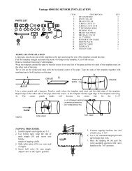
<strong>Vantage</strong> <strong>2200</strong> Parts ListPART NUMBERDESCRIPTION544717-0001 <strong>2210</strong> Electronics W/Enclosure544716-0001 2220 Electronics W/Enclosure528076-0001 Sensor Mounting Bracket (FB2/FB3/FB4)544737-0001 FB4A Sensor Head W/30 Feet Cable (<strong>Flow</strong>/Level)544737-0004 FB4B Sensor Head W/100 Feet Cable (<strong>Flow</strong>/Level)544737-0005 FB4C Sensor Head W/200 Feet Cable (<strong>Flow</strong>/Level)544729-0001 FB2A Sensor Head W/30 Feet Cable (<strong>Flow</strong>/Level)544729-0004 FB2B Sensor Head W/100 Feet Cable (<strong>Flow</strong>/Level)544729-0005 FB2C Sensor Head W/ 200 Feet Cable (<strong>Flow</strong>/Level)544536-0001 FB3A Sensor Head W/100 Feet Cable (Level)544536-0002 FB3B Sensor Head W/300 Feet Cable (Level)161105 Fuse 4-20 100 ma160978-0006 Fuse 5 x 20 mm .250 amp544700-0001 Splice Kit (Cable)500064-0028 Sensor Cable<strong>Vantage</strong> <strong>2200</strong> 3-17
WARRANTY<strong>Eastech</strong> Badger warrants meters and parts manufactured by it andsupplied hereunder to be free from defects in materials and workmanshipfor a period of 3 years from date of shipment. If within such period anymeters or parts shall be proved to Seller's satisfaction to be defective,such meters or parts shall be repaired or replaced at Seller's option.Seller's obligation hereunder shall be limited to such repair andreplacement and shall be conditioned upon Seller's receiving writtennotice of any alleged defect within 10 days after its discovery and, atSeller's option, return of such meters or parts f.o.b. to Seller's factory.THE FOREGOING WARRANTY IS EXCLUSIVE AND IN LIEU OF ALLOTHER EXPRESS OR IMPLIED WARRANTIES WHATSOEVERINCLUDING BUT NOT LIMITED TO IMPLIED WARRANTIES (EXCEPTOF TITLE) OF MERCHANTABILITY AND FITNESS FOR A PARTICULARPURPOSE. <strong>Eastech</strong> Badger shall not be liable for any defects attributableto acts or omissions of others after shipment, nor any consequential,incidental or contingent damage whatsoever.A claim for equipment damaged in transit is the sole responsibility of thecustomer.NUCLEAR DISCLAIMEREquipment sold by <strong>Eastech</strong> Badger is not intended for use in connectionwith any nuclear facility or activity unless covered by a specificquotation where the conditions of such usage will be detailed. Ifequipment is used in a nuclear facility or activity without a supportingquotation, <strong>Eastech</strong> Badger disclaims all liability for any damage, injuryor contamination, and the buyer shall indemnify and hold <strong>Eastech</strong>Badger, its officers, agents, employees, successors, assigns andcustomers, whether direct or indirect, harmless from and against any andall losses, damages or expenses of whatever form or nature (includingattorney's fees and other costs of defending any action) which they, orany of them, may sustain or incur, whether as a result of breach ofcontract, warranty, tort (including negligence), strict liability or othertheories of law, by reason of such use.All rights reserved. All data subject to change without notice.