Vantage 6000 IOM - Eastech Flow Controls
Vantage 6000 IOM - Eastech Flow Controls
Vantage 6000 IOM - Eastech Flow Controls
- No tags were found...

You also want an ePaper? Increase the reach of your titles
YUMPU automatically turns print PDFs into web optimized ePapers that Google loves.
<strong>Vantage</strong> <strong>6000</strong>Portable Ultrasonic <strong>Flow</strong> MeterInstruction Manual<strong>Eastech</strong> Badger<strong>Flow</strong> Technology Group4250 S. 76 th East Ave.Tulsa OK 74145800-226-3569
Programming KeysThe picture below shows the electronic unit with a brief description of the functions of the keys andconnections.Upstream sensorconnectionDownstream sensorconnectionPower: On/OFFNumerical Keys:Used to select menuitems and inputtingparameter values.Special Function Keys:F1= Sensor Status: View sensor strengthF2= Sensor Info: View shot type & sensorseparation.F3= NAF4= Log Data: View channel & settingsF5= NAMenu Key: Access menuselections or return to flow screen.Enter Key: Stores programmingchanges or advances through selectionscreens.Up, Down and Left/Right buttons:Used to move curser when inputtingparameters.AC power/charger andRS-232 connectionTo access the programming sections of the <strong>Vantage</strong> <strong>6000</strong>, press the Menu key. The following listwill appear on the display.01> Review Meter (Displays sensor mounting and separation and application parameters)02> Program (Program for specific application and units)03> Daily Sum (Displays up to 7 days minimum/maximum flow values and time and total)04> Data Logger (Program the setup of the Data Logger)05> System Setup (Setup of display, data port, sensor options, resetting of totalizer)06> View Signal (Displays signal wave form)3
To select the item you want press the numbers to the left of the item. For some of the items, onceyou press the appropriate numbers you will be prompted to enter a security password. The factorydefault is 00000000. Once the correct code has been entered, press the Enter key. To select theitem you want press the numbers to the left of the item. After making the desired programmingchanges, press the Menu key. You will be prompted to press the Enter key to save the changes. Ifyou press the Menu key without making changes, it will take you back to the main item list. Pressthe Menu key to return to the flow display screen. Each item on the main selection list will bediscussed in detail later in the manual.Programming the Meter for a Specific ApplicationTo program the <strong>6000</strong> for a specific application you will need to select the desired flow units,totalizer units and multiplier and program for the specific pipe information. The following shows theprogramming steps. Turn the meter on by pressing the Power key. The flow display screen willappear.Press the Menu key and the following list will be displayed:01> Review Meter (Displays sensor mounting and separation and application parameters)02> Program (Program for specific application and units)03> Daily Sum (Displays up to 7 days minimum/maximum flow values and time and total)04> Data Logger (Program the setup of the Data Logger)05> System Setup (Setup of display, data port, sensor options, resetting of totalizer)06> View Signal (Displays signal wave form)A pointer will be to the left of the item to indicate the last item that a programming change wasmade. Press the numbers 02 to enter into the Program selection. The screen will prompt you for apassword. The factory default is 00000000. If you have not put in a new password, press theEnter key or enter the password.The following list will be displayed:01> Measure Units02> Sensor Install03> Totalizer04> Damping05> Lost Signal06> Setpoints07> Meter Factor08> <strong>Flow</strong> Cutoff01>Measure Units<strong>Flow</strong> Units:Select flow units desiredGPM, MGD, etc<strong>Flow</strong> Display Format:Select format desiredXX. XX.X , etcVelocity Units:Select velocity units desiredFPS, MPSDimension Units:Select units desired.Inch, Feet, mm, etc4
02>Sensor InstallFor sensor type select 01 and sensor style V30S 1280 or V30L 640Sensor type:Select sensor style to beused01) Strap On02) Wetted03) Windowed04) SpecialSensor Style:Select sensor stylewith matchingfrequency. Taggedon side of sensors.Pipe Material:Select pipematerialCarbon Steel,PVC, etcPipe Schedule:Select pipe classor schedule. If“other”, enterwall thickness.Pipe size:Select size ofpipe. If “other”enter the pipe ODLiner Material:Select linermaterial, if any,and enterthicknessFluid Type:Water, Other.If other enter specific gravity,viscosity (cp) and fluid sonicvelocitySensor Shot Type:Select shot type usedZ, V or W shot.(See 01, Review Meter)Selecting the Sensor Shot Type will depend on the application. The V-Shot is the easiest to installbut the transmitted signal is reflected off the pipe wall and if there is corrosion on the wall this mayprevent a good reflected sensor. Switch to the Z-Shot if the meter indicates no signal. The W-Shotis used on 1 or 2 inch pipes.After the sensor shot type is selected the display will return to the selection list. Press the Menukey and the display will prompt you to press Enter to save the changes. You may press 01 forReview Meter to show the sensor mounting and sensor separation. Press the Menu or Enter keyto return to list and the press Menu to return to main flow screen. See sensor installationinstructions section for proper mounting.03>Totalizer04>Damping05>Lost SignalTotalizer Units:Select units desired,GAL, LTR, etcDamping Time:Select time desiredNone, 10 seconds, etcLost Signal Time:Select time desired5 seconds, 10 seconds, etcTotalizer Multiplier:Select multiplier desiredX10, x100, x1000, etcThis sets the response time of the meter.Lost Signal Action:Select action desiredFail to zero, Fail to Span, Hold LastThe Lost Signal allows the adjustment of time to hold the last valid flow reading. When this timehas elapsed the unit will go to the Lost Signal Action selected.06>SetpointsSet Point Selection:Select Setpoint desired.Set Point #1, #2 or #3Setpoint # xx ON:Type in flow rate desired forthe ON setpointSetpoint # xx OFF:Type in flow rate desired forthe OFF setpointThe set points can be used for the data logger storage time interval. The data logger can be set upto log at a faster interval based on the set point.5
07>Meter FactorZero Offset:01) Manual02) AutoThis allows setting or capturing any flow offsetin the meter. This is done with zero flow in thepipe. It can be manually set or auto capture.Meter Factor1.000Range .8 to 1.2This is set at the factory.08><strong>Flow</strong> CutoffApplication <strong>Flow</strong>RateShutdown 2.000000GPMWhen the flow rate goes below this valuethe meter will indicate zero flow. Enter thevalue desired.Sensor Mounting InstructionsBefore installing the sensors and sensor rails, select a section of pipe that will give 15 to 20 pipediameters of upstream straight run and 3 pipe diameters downstream. Remove any build -up of dirtor corrosion on the surface of the pipe where the sensors are to be installed. For ductile iron pipe,grind the bumps off the pipe to ensure good contact of the sensor to the pipe. If the pipe ispainted, it is not necessary to remove the paint unless there is evidence that there are severallayers of paint.There are three mounting configurations that can be used when installing the sensors to the pipe:Z-Shot, V-Shot and W-Shot.The Z-Shot configuration is where the sensors are mounted on opposite sides of the pipe. Thepicture below shows this mounting using the two long mounting rails. These can be used from 1inch to 24 inch pipes (maximum sensor separation of 8 inches).SensorSeparationDownstream Sensor-2 to 8 Inch Rail<strong>Flow</strong>Upstream Sensor0 to 8 Inch RailSensor Clamp6
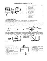
For horizontal pipes, set the longest rail (the one that has a scale of 0 to 8 inches) on top of thepipe and wrap the chains around the pipe and connect the chains to the hook on the thumbscrewassembly.Take up some the slack in the chain with the wing nut but not so tight that you can not rotate therail on the pipe.Rotate the sensor rail on the pipe so that the bubble on the level is between the two lines. Tightenthe wing nut to secure the rail to the pipe. Use a length of paper from the roll of template paper towrap around the pipe next one of the ends of the mounting rail. This will be used to position theother rail.Set the other long rail (the one with the scale of –2 to 8 inches) on the pipe and wrap the chainsaround the pipe with the chains going over the slots in the first rail. Connect the chain to the hookas with the first rail. Rotate the sensor rail on the pipe so that the bubble on the level is betweenthe two lines. Before tightening the chain verify that the end of the rail is 7/8” from the edge of thetemplate paper, and then tighten the chain with the wing nut to secure the rail to the pipe.For vertical pipes, the procedure is the same except instead of using the bubble levels you willneed to position the second rail so that the distance between the rails across the pipe is equal.Once the rails are secured properly to the pipe the sensors can be installed. Place a bead of theDow Corning 111 silicone grease in the middle of the face of the sensor along its length.Install the sensor marked 1 in the mounting rail (0 to 8 inches) with the end opposite where thesensor cable come out lined up with the Zero on the scale. Mount the sensor marked 2 in the othermounting rail (-2 to 8 inches) with the end opposite where the sensor cable come out lined up withthe number on the scale to give the sensor separation indicated in Review Meter selection or bypressing the F2 key when the main flow screen is present.Once the sensors are mounted connect the number 1 sensor to the upstream connection on thehandheld electronics unit and the number 2 sensor to the downstream connection. The sensorconnectors are keyed so you may need to rotate the connector on the cable until it makes theproper alignment and then screw the connector until tight.7
The other Z-Shot configuration uses one long rail and the short rail. These can be used for pipesizes 14 inches and larger as shown in the picture below.Upstream SensorSensorSeparationTemplate<strong>Flow</strong>The mounting of the rails is the same except that a template is used to assist in positioning thesensor separation. A roll of template paper is provided with the <strong>Vantage</strong> <strong>6000</strong>.Cut a length of the template paper that is the circumference of the pipe and tape it to the pipe.Mount the smaller rail so that the bubble is level and the inside opening in the rail (where sensor ismounted) is even with the template. On the opposite side of the pipe, measure from the outside ofthe template and mark on the pipe the sensor separation calculated by the handheld electronicunit. Mount the other rail and position it on the pipe so the edge of the opening for the sensor linesup with the mark you made on the pipe and the bubble on the level on the rail is centered.Install the sensors as previously described with the other Z-Shot configuration.The V-Shot and W-Shot configurations are where the sensors are mounted on the same side of thepipe as shown in the picture below.Upstream SensorSensorSeparationDownstream SensorDownstream Sensor<strong>Flow</strong>The large sensor mounting rail is used for the V-Shot configuration up to 12 inch pipes. For largerpipes the small mounting rail is used in conjunction with the large rail. The mounting of the rail(s)to the pipe is the same procedure as described in the Z-Shot mounting. It is not necessary for therail to be level when using the large rail only. But the rail should never be mounted at the top orbottom of a horizontal pipe.Pipe preparation and installation of the sensors are the same as described in the Z-Shotprocedure. The sensors are to be mounted so that the inside to inside spacing of the two sensorsis the value calculated by the handheld electronic unit for the specific application.The W-Shot is used for 1 to 2 inch pipes with the small sensors.8
Description of Other Main Menu Selections03) Daily SumThe Daily Sum records the minimum and maximum flow values and time and the total flow for a 24hour period and stores the last 7 days. To select this item, press Menu key and then the 0 and 3keys. To view the previous day, press the Left Arrow key.04) Data LoggerThe Data Logger has up to 8 channels that can be assigned to store flow values such as flow, totaland velocity. The storage rate is selectable from one minute to 60 minutes. For flow or velocityvalues it stores the average value over the selected time interval. For the totalizer it stores theaccumulated totalizer value at the time of the selected time interval.To download the data, connect the Serial Com cable to the handheld connector on bottom of unitand the RS-232 on the computer where the <strong>Vantage</strong> DDS software is installed. See the instructionmanual for the for installing the <strong>Vantage</strong> DDS software and doTo select this item press the Menu key and then the 0 and 4 keys. The Password screen willappear. The factory default is 00000000. The following list will be displayed. A description foreach item is listed beside the item.01)Set Time Date02)Storage Rate03)SecondarySet time Date:To set the internal clock for time and date.Storage Rate:To select time interval for logged dataSecondary:To select time interval for secondary time value04)Log Channels05)Logged GraphLog Channel #:Select channel number toset logging functionSelect Channel # to viewgraph of data. Use left orright button to scroll throughdata.Select desired loggingfunction for identified channel.Y Range (F2)= Sets range of Y on graphY Start (F3)= Sets start value of Y rangeX Range= Using left or right arrow buttons willscroll time of X axis.06)Logged DataTo review programmed Channels and the Presentlogged functions.07)Amount StoredTo view the logger time and time to store and theamount of bytes stored and the amount of free space.08)Clear DataTo clear the data logger of all logged data.Press “5” to clear.9
05) System SetupThe System Setup selection contains items for the basic set up of the meter such as, setting up thedisplay contrast and back light, serial communications, resetting of totalizer, etc.. Press the Menukey and then the 0 and 5 keys. The Password screen will appear. The factory default is00000000. Press the Enter key and the following list will be displayed. A description for each itemis listed beside the item. To select the desired item, press the number keys for that item.01)Display02)Data PortDisplay Settings01) Contrast02) BacklightRS-232 Comm Port01) Baud Rate02) <strong>Flow</strong> ControlThe Contrast allows up to 8 differentsettings.The Backlight allows you to turn off, turnon or have the backlight timed off toconserve battery. It also allows theadjustment of the brightness.These selections allow selectingthe baud rate and flow controlparameters.03)Display ModesDisplay Mode 01 is the onlyfunction used at this time.04)Total ResetTo Reset the totalized values to zero05)New PasswordTo Enter a new Password forsecurity.Shipped from factory as 0000000006)Summary ResetTo reset the Summary values to zero07)Sensor Option01) To select sensor power to High orNormal values. Typically strap onsensor are selected as High power.02) To select Normal or Reversed sensorpolarity. Can be used is sensors areconnected backwards withoutreconnecting.08)Meter ResetTo Reset the meter to factory defaultparameters. Unit will need to bereprogrammed to application data.09)New FirmwareDO NOT USE THIS SCREEN:Unless the latest firmware from the factory hasbeen provided.10
06) View SignalThis selection allows the viewing of the signal. The signal should be a uniform sinusoidal wave. Ifthe signal is distorted, try recycling the power or reposition the sensors. Press the Menu key andthen the 0 and 6 keys. To refresh the displayed signal press the F5 key.Components of the <strong>Vantage</strong> <strong>6000</strong>DescriptionPart NumberHandheld electronic unit 544743-0001V30L 640 sensor (2)* 544746-0001V30S 1280 sensor (2)* 544747-0001Speedrail V-Shot 544727-0001Speedrail Z-Shot up to 12” pipe 544726-0001Speedrail Z-Shot 14” and larger pipe ** 544725-0001Sensor Clamps (2) 528360-0001Thumb Screw (2) 528304-0002AC adaptor/battery charger cable 544748-0001Serial communications cable 544749-0001External battery power cable 544750-0001Sensor cable extension 18 Ft. *** 501733-0002*May have one or both sets of sensors depending on unit ordered.**Not supplied if only V30S 1280 sensor ordered.***Optional11