simulation of a superheterodyne receiver using pspice - School of ...
simulation of a superheterodyne receiver using pspice - School of ...
simulation of a superheterodyne receiver using pspice - School of ...

Create successful ePaper yourself
Turn your PDF publications into a flip-book with our unique Google optimized e-Paper software.
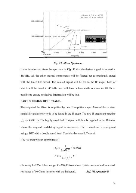
Fig. 23: Mixer Spectrum.<br />
It can be observed from the spectrum in Fig. 35 that the desired signal is located at<br />
455kHz. All the other spectral components will be filtered out as previously stated<br />
with the tuned LC circuit. The desired signal will be fed to the IF stages, both <strong>of</strong><br />
which will be tuned to 455kHz and will have a bandwidth as close to 10kHz as<br />
possible to ensure no desired information will be lost.<br />
PART 5: DESIGN OF IF STAGE.<br />
The output <strong>of</strong> the Mixer is amplified by two IF amplifier stages. Most <strong>of</strong> the <strong>receiver</strong><br />
sensitivity and selectivity is to be found in the IF stage. The two IF stages are tuned to<br />
f IF<br />
(= 455kHz). The highly amplified IF signal will then be applied to the Detector<br />
where the original modulating signal is recovered. The IF amplifier is configured<br />
<strong>using</strong> a BJT with a double tuned load. Consider the tuned LC circuit.<br />
If Q>10 then we can approximate:<br />
1<br />
f<br />
O<br />
≈<br />
2π<br />
LC<br />
1<br />
∴C<br />
≈<br />
2<br />
4π<br />
f<br />
2<br />
O<br />
= 455kHz<br />
F<br />
L<br />
Choosing L=175uH then we get C=700pF from above. (Note: we also add in a small<br />
resistance <strong>of</strong> 10 Ohms in series with the inductor).<br />
Ref. [1] Appendix B<br />
24