Ionization Smoke Detector P.1.17.01-3 - ORR Protection
Ionization Smoke Detector P.1.17.01-3 - ORR Protection
Ionization Smoke Detector P.1.17.01-3 - ORR Protection

Create successful ePaper yourself
Turn your PDF publications into a flip-book with our unique Google optimized e-Paper software.
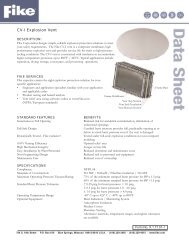
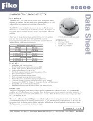
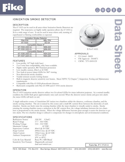
IONIZATION SMOKE DETECTOR<br />
DESCRIPTION<br />
The 67-1033 can be used in all areas where <strong>Ionization</strong> <strong>Smoke</strong> <strong>Detector</strong>s are<br />
required. The responsive yet highly stable operation allows the 67-1033 to<br />
fit in a wide range of uses. It can be used in areas where early warning of<br />
superheated or flaming combustibles is expected.<br />
<strong>Ionization</strong> <strong>Smoke</strong> <strong>Detector</strong><br />
Fike P/N<br />
Mfg. P/N<br />
67-1033 SIJ-24<br />
Compatible Bases 6”<br />
67-1034 (430 Ω) NS6-224<br />
67-1035 (220 Ω) NS6-220<br />
Compatible Bases 4”<br />
67-1036 (430 Ω) NS4-224<br />
67-1037 (220 Ω) NS4-220<br />
FEATURES<br />
• Low profile, 1.8” high (with base)<br />
• 2 or 4 wire base compatibility, relay bases available<br />
• Highly stable operation, RF/Transient protection<br />
• Low standby current, 40mA at 24 VDC<br />
• Two built-in power/alarm LEDs for 360° viewing<br />
• Non-directional smoke chamber<br />
• Vandal resistant security locking feature<br />
P/N 67-1033<br />
APPROVALS<br />
• UL Listed - S4021<br />
• FM Approval - 3010873<br />
• CSFM - 7271-0410:135<br />
• Built-in magnetic detector sensitivity test feature. Meets NFPA 72, Chapter 7, Inspection, Testing and Maintenance<br />
requirements.<br />
• Compatible with Fike 63-1024 photoelectric detector<br />
• Backwards compatible with Fike 63-1008 and 67-1016 smoke detector<br />
OPERATION<br />
The 67-1033 ionization smoke detector utilizes two bi-colored LEDs for status indication purposes. In a normal standby<br />
condition the LEDs flash green approximately once each second. When the detector senses smoke and goes into alarm<br />
the status LEDs will latch on red.<br />
A single radioactive source of Americium-241 ionizes two chambers within the detector, a reference chamber, and the<br />
smoke sensing chamber. The air is ionized by this source and a small DC current flows between the electrodes of each<br />
chamber. <strong>Smoke</strong> can freely enter the sensing chamber while the inner chamber is virtually sealed to smoke. <strong>Smoke</strong><br />
entering the sensing chamber causes a reduction in the DC current flow, the voltage imbalance between the two chambers<br />
is proportional to the smoke density. When the voltage differences become great enough it causes the detector to go<br />
into alarm. The two chamber design is utilized to compensate for changes in atmospheric and environmental conditions.<br />
SPECIFICATIONS<br />
Radioactive Source AM-241 0.5mCi<br />
Rated Voltage<br />
17.7 - 30.0 VDC<br />
Working Voltage 15.0 - 33.0 VDC<br />
Maximum Voltage<br />
42 VDC<br />
Supervisory Current 40mA @ 24 VDC<br />
Surge Current<br />
200mA max. @ 24 VDC<br />
Alarm Current<br />
150mA max. @ 24 VDC<br />
Ambient Temperature 32°F to 120°F<br />
(0°C to 49°C)<br />
Color & Case Material Bone PC/ABS Blend<br />
Sensitivity Test Feature: Magnetically activated<br />
dual reed switch test<br />
Form No. <strong>P.1.17.01</strong>-3<br />
704 S. 10th Street · P.O. Box 610 · Blue Springs, Missouri 64013-0610 U.S.A. · (816) 229-3405 · (816) 229-4615 · www.fi ke.com
ENGINEERING SPECIFICATIONS<br />
The contractor shall furnish and install where indicated on the plans, the 67-1033 ionization smoke detectors. The<br />
combination detector head and twist-lock base shall be UL listed compatible with a UL listed fire alarm panel.<br />
The base shall permit direct interchange with 63-1024 photoelectric type smoke detector, the 63-1025 combination<br />
photoelectric/heat detector, and/or 60-1029 or 60-1030 fixed temperature/rate-of-rise heat detectors. The base shall be<br />
a listed, compatible twistlock base. In the event of partial or complete retrofit, the 67-1033 may be used in conjunction<br />
with, or as a replacement for, Fike detectors (63-1007, 63-1016 and the 67-1016).<br />
The smoke detector shall have two flashing status LEDs for visual supervision. When the detector is in standby condition<br />
the LEDs will flash Green. When the detector is actuated, the flashing LEDs will latch on Red. The detector may be<br />
reset by actuating the control panel reset switch.<br />
The sensitivity of the detector shall be capable of being verified. It shall be possible to perform a functional test of the<br />
detector without the need of generating smoke. The test method shall simulate effects of products of combustion in the<br />
chamber to ensure testing of the detector electronics.<br />
To facilitate installation, the detector shall be non-polarized. Voltage and RF transient suppression techniques shall be<br />
employed to minimize false alarm potential. Auxiliary SPDT relays shall be installed where indicated.<br />
The vandal-resistant, security locking feature shall be used in those areas as indicated on the drawing. The locking feature<br />
shall be field removable when not required.<br />
IONIZATION SMOKE DETECTOR SENSITIVITY TEST FEATURE<br />
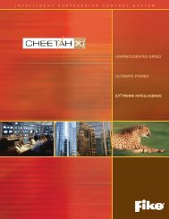
Test Procedure<br />
1. With detector wired to appropriate initiating circuit or current limited power source and with normal applied power,<br />
place a magnet as shown in Figure 1.<br />
2. Wait at least six seconds. <strong>Detector</strong> SHOULD NOT alarm and LED should not light.<br />
3. Place magnet on detector as shown in Figure 2 (opposite side).<br />
4. Wait at least six seconds. <strong>Detector</strong> SHOULD alarm.<br />
5. If detector does alarm when magnet is positioned as in Figure 1 or does not produce an alarm when magnet is<br />
positioned as in Figure 2, detector is not within specified sensitivity limits and may require service.<br />
WARNING: Conduct testing only under Normal Standby conditions. Abnormal or Low Power conditions may affect<br />
sensitivity. Always reset power prior to testing of next unit.<br />
Figure 1 LED’s<br />
Figure 2<br />
R<br />
Copyright © Fike Corporation All Rights Reserved.<br />
Form No. <strong>P.1.17.01</strong>-3 June, 2006 Specifi cations are subject to change without notice.