EPACO⢠Bus Network Technology
EPACO⢠Bus Network Technology
EPACO⢠Bus Network Technology

You also want an ePaper? Increase the reach of your titles
YUMPU automatically turns print PDFs into web optimized ePapers that Google loves.
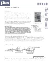
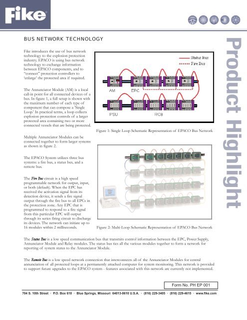
BUS NETWORK TECHNOLOGYFike introduces the use of bus networktechnology to the explosion protectionindustry. EPACO is using bus networktechnology to exchange informationbetween EPACO components, and to“connect” protection controllers to‘enlarge’ the protected area if required.The Annunciator Module (AM) is a localcall-in point for all connected devices of abus. In figure 1, a full setup is shown withthe maximum number of each type ofcomponent that can compose a ‘SingleLoop.’ In practical terms, a loop collectsexplosion protection controls of a largerprotected area containing two or moreconnected vessels that are being protected.Multiple Annunciator Modules can beconnected together to form larger systemsas shown in figure 2.Figure 1: Single Loop Schematic Representation of EPACO <strong>Bus</strong> <strong>Network</strong>The EPACO System utilizes three bussystems: a fire bus, a status bus, and aremote bus.The Fire <strong>Bus</strong> circuit is a high speedprogrammable network for output, input,or both (default). When the EPC hasreceived the activation signal from itsdetection device, it sends a fire signaloutput through the fire bus to all EPCs inthe protection zone. Any EPC that isprogrammed to respond to a fire signalfrom this particular EPC will outputthrough its series firing circuit to dischargeits devices. The network can initiate up to16 modules within 2 milliseconds.Figure 2: Multi-Loop Schematic Representation of EPACO <strong>Bus</strong> <strong>Network</strong>The Status <strong>Bus</strong> is a low speed communication bus that transmits control information between the EPC, Power Supply,Annunciator Module and Relay modules. The status bus ties all the various modules together to form a network forreporting of system status to the Annunciator Module.The Remote <strong>Bus</strong> is a low speed network connection that interconnects all of the Annunciator Modules for centralannunciation of all protected loops at a permanently attached computer for system monitoring. This network is providedto support future upgrades to the EPACO system - features associated with this network are currently not implemented.Form No. PH EP 001704 S. 10th Street · P.O. Box 610 · Blue Springs, Missouri 64013-0610 U.S.A. · (816) 229-3405 · (816) 229-4615 · www.fike.com
The number and type of devices used in a loop are driven by:1. The number of EPCs involved in the protected area. Hereby, the following needs to be considered:• Two(2) is the maximum number of 4-20 mA detection transducers that can be connected to an EPC,eventually additional switch type detectors can be connected. It is also possible, if the protection design ismade accordingly, to use multiple, parallel wired, switch type detectors as the sole method of detection (*Alsorefer to section Frequently Asked Questions for more information).• Each EPC has one(1) output to activate simultaneously a maximum of six(6) actuators or protection devices,wired in series. If for instance the volume/geometry of the vessel to be protected requires the use of morethan six(6) actuators, a second EPC can be added to the loop. The two(2) EPCs protecting that vessel areconnected through the ‘fire bus’ (see figure above).The table below details the number of GCAs used per componentComponentNumber of GCAs per componentSuppression Container 1Isolation Valve 2-10” 1Isolation Valve 12-18” 2Isolation Valve 20” 32. The number and type of relay contacts required for establishing an interface between EPACO and the overallprocess control system. Each EPC is equipped with 2 relays: 1 relay output to indicate alarm/release (NO/NCtype, 24 V-1A resistive load, energized in a non-alarm/unreleased state) and 1 relay output to indicatetrouble/supervisory (NO/NC type, 24 V-1A resistive load energized in non-trouble/supervisory state). Ifmore relays or relays that switch on different events are required, a Relay Card (RC8, adding 8 relay contacts,powered by PSU) can be added to the loop.3. Power supply through the Power Supply Unit (PSU) (and connected transformer/batteries) is required when morethan one(1) EPC is used, or as soon as devices other than the EPC are involved.The benefits that an advanced bus network offers can be summarized as follows:• Simplified explosion protection system design and configuration.• Easier and more economic installation, less cabling involved.• Faster commissioning, debugging and startup.• New devices can be added by simply attaching them to the bus. No tracing or labeling of circuits is required.• One configuration software package can be used for all connected devices.• Commissioning and diagnostics can be remotely performed from the Annunciator Module (AM) of thatprotection loop. In this way, information regarding field instruments’ health, historical trending can be accessedremotely. This is important since enclosures of live powered circuitry/controls cannot be opened when installed inhazardous areas.• The local EPC provides power to connected field instruments; no additional external power is required.• Improved process reliability because control failures tend to be isolated to particular process elements or areas.• The process of future development of additional instrumentation and control systems is simplified.For details on electrical wiring and connections, refer to each device’s Installation and Operation Instruction manual.Copyright © Fike Corporation All Rights Reserved.Form No. PH EP 001 January, 2006 Specifications are subject to change without notice.