P.1.51.01 Intelligent Duct Smoke Detectors.indd - ORR Protection
P.1.51.01 Intelligent Duct Smoke Detectors.indd - ORR Protection
P.1.51.01 Intelligent Duct Smoke Detectors.indd - ORR Protection

You also want an ePaper? Increase the reach of your titles
YUMPU automatically turns print PDFs into web optimized ePapers that Google loves.
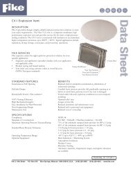
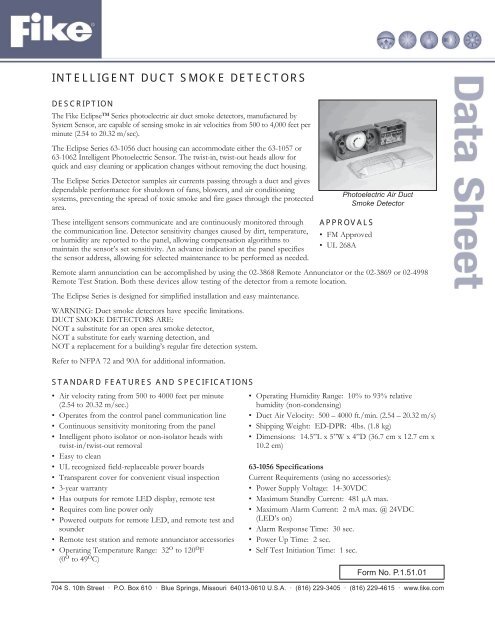
INTELLIGENT DUCT SMOKE DETECTORS<br />
DESCRIPTION<br />
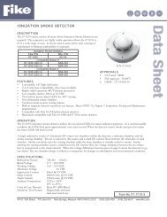
The Fike Eclipse Series photoelectric air duct smoke detectors, manufactured by<br />
System Sensor, are capable of sensing smoke in air velocities from 500 to 4,000 feet per<br />
minute (2.54 to 20.32 m/sec).<br />
The Eclipse Series 63-1056 duct housing can accommodate either the 63-1057 or<br />
63-1062 <strong>Intelligent</strong> Photoelectric Sensor. The twist-in, twist-out heads allow for<br />
quick and easy cleaning or application changes without removing the duct housing.<br />
The Eclipse Series Detector samples air currents passing through a duct and gives<br />
dependable performance for shutdown of fans, blowers, and air conditioning<br />
systems, preventing the spread of toxic smoke and fire gases through the protected<br />
area.<br />
These intelligent sensors communicate and are continuously monitored through<br />
the communication line. Detector sensitivity changes caused by dirt, temperature,<br />
or humidity are reported to the panel, allowing compensation algorithms to<br />
maintain the sensor’s set sensitivity. An advance indication at the panel specifies<br />
the sensor address, allowing for selected maintenance to be performed as needed.<br />
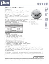
Photoelectric Air <strong>Duct</strong><br />
<strong>Smoke</strong> Detector<br />
APPROVALS<br />
• FM Approved<br />
• UL 268A<br />
Remote alarm annunciation can be accomplished by using the 02-3868 Remote Annunciator or the 02-3869 or 02-4998<br />
Remote Test Station. Both these devices allow testing of the detector from a remote location.<br />
The Eclipse Series is designed for simplified installation and easy maintenance.<br />
WARNING: <strong>Duct</strong> smoke detectors have specific limitations.<br />
DUCT SMOKE DETECTORS ARE:<br />
NOT a substitute for an open area smoke detector,<br />
NOT a substitute for early warning detection, and<br />
NOT a replacement for a building’s regular fire detection system.<br />
Refer to NFPA 72 and 90A for additional information.<br />
STANDARD FEATURES AND SPECIFICATIONS<br />
• Air velocity rating from 500 to 4000 feet per minute<br />
(2.54 to 20.32 m/sec.)<br />
• Operates from the control panel communication line<br />
• Continuous sensitivity monitoring from the panel<br />
• <strong>Intelligent</strong> photo isolator or non-isolator heads with<br />
twist-in/twist-out removal<br />
• Easy to clean<br />
• UL recognized field-replaceable power boards<br />
• Transparent cover for convenient visual inspection<br />
• 3-year warranty<br />
• Has outputs for remote LED display, remote test<br />
• Requires com line power only<br />
• Powered outputs for remote LED, and remote test and<br />
sounder<br />
• Remote test station and remote annunciator accessories<br />
• Operating Temperature Range: 32 o to 120 o F<br />
(0 o to 49 o C)<br />
• Operating Humidity Range: 10% to 93% relative<br />
humidity (non-condensing)<br />
• <strong>Duct</strong> Air Velocity: 500 – 4000 ft./min. (2.54 – 20.32 m/s)<br />
• Shipping Weight: ED-DPR: 4lbs. (1.8 kg)<br />
• Dimensions: 14.5”L x 5”W x 4”D (36.7 cm x 12.7 cm x<br />
10.2 cm)<br />
63-1056 Specifications<br />
Current Requirements (using no accessories):<br />
• Power Supply Voltage: 14-30VDC<br />
• Maximum Standby Current: 481 μA max.<br />
• Maximum Alarm Current: 2 mA max. @ 24VDC<br />
(LED’s on)<br />
• Alarm Response Time: 30 sec.<br />
• Power Up Time: 2 sec.<br />
• Self Test Initiation Time: 1 sec.<br />
Form No. <strong>P.1.51.01</strong><br />
704 S. 10th Street · P.O. Box 610 · Blue Springs, Missouri 64013-0610 U.S.A. · (816) 229-3405 · (816) 229-4615 · www.fi ke.com
RELAY CONTACT RATINGS (EACH SET OF FORM C CONTACTS)<br />
Current Ratings Maximum Voltage Load Description Application<br />
3A 30VDC Resistive Non Coded<br />
2A 30VDC Resistive Coded<br />
.9A 110VDC Resistive Non Coded<br />
.9A 125VAC Resistive Non Coded<br />
.5A 30VDC Inductive (L/R=5ms) Coded<br />
1A 30VDC Inductive (L/R=2ms) Coded<br />
.3A 125VAC Inductive (PF=.35) Non Coded<br />
.7A 75VAC Inductive (PF=.35) Non Coded<br />
1.5A 25VAC Inductive (PF=.35) Non Coded<br />
ACCESSORY CURRENT LOADS AT 24VDC<br />
Device Standby Alarm<br />
02-3868 0 mA 4.6 mA Max.<br />
02-3869/02-4998 0 mA 4.6 mA Max.<br />
AVAILABLE MODELS<br />
Description<br />
Eclipse Series intelligent duct smoke<br />
detector housing<br />
Fike P/N<br />
63-1056<br />
Photoelectric duct sensor head 63-1057<br />
Photoelectric isolator duct sensor head 63-1062<br />
Metal sampling tube duct widths 1’–2 02-3721<br />
Metal sampling tube duct widths 2’–4’ 02-3722<br />
Metal sampling tube duct widths 4’–8’ 02-3723<br />
Metal sampling tube duct widths 8’–12 02-3724<br />
Replacement Eclipse Power Board 20-1077<br />
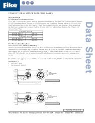
Remote test station (see right) 02-3869<br />
Remote test station w/key (see right) 02-4998<br />
Remote LED (see right) 02-3868<br />
Replacement filters 20-1078<br />
End cap for metal sampling tube 20-1070<br />
Replacement plastic sampling tub 20-1080<br />
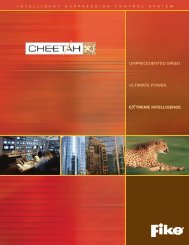
02-3869<br />
Remote Test Station<br />
(UL S2522)<br />
02-3868<br />
Remote Annunciator<br />
(UL S2522)<br />
02-4998<br />
Remote Test Station<br />
with key (UL S2522)
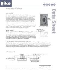
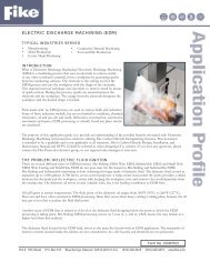
Wiring Diagram: 63-1056 <strong>Duct</strong> <strong>Smoke</strong> Detector Using a UL Listed Control Panel<br />
LISTED COMPATIBLE<br />
CONTROL PANEL<br />
SLC<br />
+<br />
SLC<br />
-<br />
(+) COM LINE<br />
TO REST OF SYSTEM<br />
1 2 3 4 5 6 7 8 9 10 11 12 13 14 1 2 3 1 2 3<br />
(–) COM LINE<br />
TO REST OF SYSTEM<br />
1 2<br />
3<br />
OPTIONAL RETURN LOOP<br />
NOTE: For terminals 9 through 14, normally closed and normally opened relay positions are defined with product in reset condition, not in alarm.<br />
Wiring Diagram: 63-1056 <strong>Duct</strong> <strong>Smoke</strong> Detector<br />
with Optional 02-3868<br />
Wiring Diagram: 63-1056 <strong>Duct</strong> <strong>Smoke</strong> Detector<br />
with 02-3869/02-4998<br />
(+)<br />
(–)<br />
6 (+)<br />
4<br />
(–)<br />
RED<br />
RTS451/<br />
451KEY<br />
GROUND<br />
5<br />
4<br />
1<br />
2<br />
ALARM<br />
(LED)<br />
TEST (+) 8<br />
4 TEST (+)<br />
DUCT DETECTOR<br />
RA400Z<br />
REMOTE<br />
ANNUNCIATOR<br />
NOTE: Break tab on 02-3868 for use with 63-1056<br />
TEST (–) 7<br />
5 TEST (–)<br />
DUCT DETECTOR<br />
RTS451/RTS451KEY<br />
REMOTE TEST STATION<br />
ARCHITECT AND ENGINEERING SPECIFICATIONS<br />
The duct smoke detector shall be a Fike Model 63-1056 <strong>Intelligent</strong> <strong>Duct</strong> <strong>Smoke</strong> Detector to be used with compatible<br />
control panels. The duct smoke detector shall be UL listed per UL 268A, Standard for <strong>Smoke</strong> <strong>Detectors</strong> for <strong>Duct</strong><br />
Applications, specifically for use in air handling systems. The detector shall operate in air velocities from 500 to 4000 feet<br />
per minute. The detector housing shall be equipped with an integral mounting base capable of accommodating the 63-1062<br />
photoelectric detector head. It shall be capable of remote testing from the 02-3869 or 02-4998 Remote Test Station. The<br />
duct smoke detector housing shall incorporate an airtight smoke chamber in compliance with UL 268A. The housing shall<br />
be capable of mounting to either rectangular or round ducts without adapter brackets. An integral filter system shall be<br />
included to reduce dust and residue effects, thereby reducing maintenance and servicing. Sampling tubes shall be easily<br />
installed after the housing is mounted to the duct by passing through the duct housing. Terminal connections shall be of the<br />
strip and clamp method suitable for 14-18 AWG wiring.<br />
R<br />
Copyright © Fike Corporation All Rights Reserved.<br />
Form No. <strong>P.1.51.01</strong> April, 2004 Specifi cations are subject to change without notice.