Electric Discharge Machining - Fire Protection Technologies
Electric Discharge Machining - Fire Protection Technologies
Electric Discharge Machining - Fire Protection Technologies

Create successful ePaper yourself
Turn your PDF publications into a flip-book with our unique Google optimized e-Paper software.
ELECTRIC DISCHARGE MACHINING (EDM)<br />
TYPICAL INDUSTRIES SERVED<br />
• Manufacturing<br />
• Mold Production<br />
• Exotic Metal <strong>Machining</strong><br />
• Conductive Material <strong>Machining</strong><br />
• Tool and Die Production<br />
INTRODUCTION<br />
What is Electronic <strong>Discharge</strong> <strong>Machining</strong>? Electronic <strong>Discharge</strong> <strong>Machining</strong><br />
(EDM) is a machining process that uses an electrode to remove metal,<br />
or any other conductive material, from a workpiece by generating sparks<br />
between conducting surfaces. The electrode is the cutting tool for the<br />
EDM process and cuts the workpiece with the shape of the electrode.<br />
This material removal technique uses electricity to remove metal by means<br />
of spark erosion. During this process, sparks are created between the<br />
electrode and the workpiece. The energy from the electrode dissipates the<br />
workpiece and the desired shape is formed.<br />
Parts made with he EDM process are used in various fields and industries.<br />
Some of these industries include, but are not limited to: medicine, chemical,<br />
electronics, oil and gas, die and mold, fabrication, construction, automotive,<br />
aeronautics and space, EDM processing is virtually found any place metals<br />
are machined.<br />
The purpose of this application guide is to provide an understanding of the possible hazards associated with Electronic<br />
<strong>Discharge</strong> <strong>Machining</strong> and protection solutions utilizing Fike Carbon Dioxide Extinguishing Systems. This document<br />
is intended to be a guideline and is not applicable to all situations. Fike’s Carbon Dioxide Design, Installation, and<br />
Maintenance Manual and NFPA 12 shall be referred to when designing CO 2 systems. If you have any questions, please<br />
contact the Fike <strong>Protection</strong> Systems group, or our regional sales manager in your area.<br />
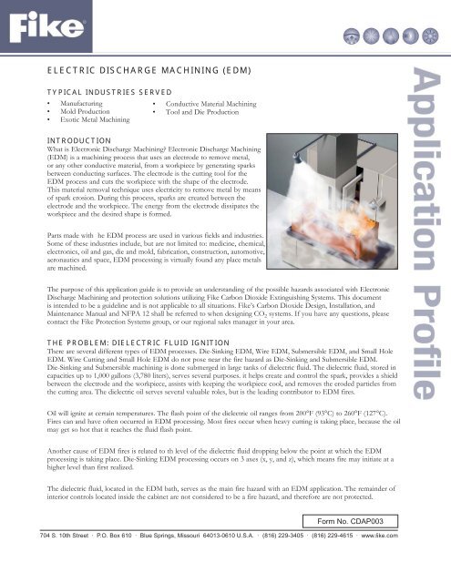
THE PROBLEM: DIELECTRIC FLUID IGNITION<br />
There are several different types of EDM processes. Die-Sinking EDM, Wire EDM, Submersible EDM, and Small Hole<br />
EDM. Wire Cutting and Small Hole EDM do not pose near the fire hazard as Die-Sinking and Submersible EDM.<br />
Die-Sinking and Submersible machining is done submerged in large tanks of dielectric fluid. The dielectric fluid, stored in<br />
capacities up to 1,000 gallons (3,780 liters), serves several purposes. it helps create and control the spark, provides a shield<br />
between the electrode and the workpiece, assists with keeping the workpiece cool, and removes the eroded particles from<br />
the cutting area. The dielectric oil serves several valuable roles, but is the leading contributor to EDM fires.<br />
Oil will ignite at certain temperatures. The flash point of the dielectric oil ranges from 200°F (93°C) to 260°F (127°C).<br />
<strong>Fire</strong>s can and have often occurred in EDM processing. Most fires occur when heavy cutting is taking place, because the oil<br />
may get so hot that it reaches the fluid flash point.<br />
Another cause of EDM fires is related to th level of the dielectric fluid dropping below the point at which the EDM<br />
processing is taking place. Die-Sinking EDM processing occurs on 3 axes (x, y, and z), which means fire may initiate at a<br />
higher level than first realized.<br />
The dielectric fluid, located in the EDM bath, serves as the main fire hazard with an EDM application. The remainder of<br />
interior controls located inside the cabinet are not considered to be a fire hazard, and therefore are not protected.<br />
Form No. CDAP003<br />
704 S. 10th Street · P.O. Box 610 · Blue Springs, Missouri 64013-0610 U.S.A. · (816) 229-3405 · (816) 229-4615 · www.fi ke.com
THE SOLUTION: LOCAL APPLICATION/RATE-BY-AREA<br />
The CO 2 Rate-By-Area design method is used to protect two-dimensional, horizontal surfaces and low-level objects.<br />
For EDM applications, the Rate-By-Area design method is applied because the potential fire is two-dimensional. A<br />
“liquid surface” is any pool of liquid 0.25” (6mm) or more in depth. <strong>Electric</strong> <strong>Discharge</strong> Machine baths will exceed a<br />
minimum depth of .25” (6mm), therefore the application fits the description for a Liquid Surface design.<br />
EDM oil tank surfaces are generally small in size; therefore the discharge rate will be moderate. The total quantity of<br />
CO 2 can be supplied in a single cylinder.<br />
In addition to installing a carbon dioxide fire suppression system, additional EDM safeguards should be considered if<br />
not implemented. These safeguards include installing a coolant system to maintain a proper oil temperature, a low oil<br />
level switch on the recirculating oil tank, and a means to shut down the oil system and EDM unit in the event of a fire.<br />
NOZZLE SELECTION<br />
Nozzle quantity and location is a key factor when applying CO 2 protection to a Liquid Surface. The Rate-By-Area<br />
method for CO 2 fire protection utilizes the “S” Type Nozzle, which directs the Carbon Dioxide agent discharge in a<br />
specific pattern toward the protected surface. This method of agent application is effective only when the proper agent<br />
flow rate and nozzle height are applied to a specific coverage area. The height of the nozzle above the surface being<br />
protected and the total number of nozzles must be determined to calculate the appropriate nozzle flow rate. Placement<br />
of the CO 2 nozzle must not interfere with the operation or maintenance of the machine. The nozzle must also be<br />
installed at a location that will enable an extinguishing “envelop” to be developed around the entire protected area.<br />
Any obstructions that could interfere with the flow of CO 2 from the nozzle to the protected surface must be avoided<br />
to provide proper system performance. Input from the EDM owner or operator is important at the time of system<br />
design.<br />
DETECTION AND CONTROLS<br />
Automatic fire protection is implemented when protecting EDM applications. Quite often, machines are programmed<br />
to operate without machinist present. A flame detector or linear heat detector is installed to detect a fire and activate<br />
the CO 2 system. The detector should be installed in a position to view and detect any fire. The detector must be<br />
carefully installed and not interfere with the operation, but must still serve its purpose.<br />
For this application, Fike’s Single Hazard Panel (SHP) is the best-suited releasing control panel. A pressure switch is<br />
also recommended to provide a positive pneumatic confirmation to the SHP that the CO 2 system has discharged. The<br />
pressure switch provides the input to the SHP needed to shut down oil pumps and the machine to confine the fire and<br />
prevent the oil from re-igniting.<br />
Audible and visual devices are installed to warn<br />
nearby personnel of the CO 2 discharge. A manual<br />
release station is conveniently located to allow<br />
electrical manual CO 2 operation. The SHP panel<br />
relay contacts can be tied into he facility fire alarm<br />
system notifying personnel of a trouble or alarm<br />
condition. This will provide proper response into the<br />
event of a fire.<br />
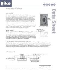
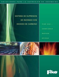
A Fike CO 2 system protecting an EDM process is<br />
shown in the illustration below.<br />
References:<br />
Sommer, Carl. (2000). Non-Traditional <strong>Machining</strong><br />
Handbook. Houston, TX: Advance Publishing, Inc.<br />
R<br />
“Electronic <strong>Discharge</strong> Machine” Protected by a<br />
Fike Carbon Dioxide Suppression System<br />
Copyright © Fike Corporation All Rights Reserved.<br />
Form No. CDAP003 May, 2008 Specifi cations are subject to change without notice.