Electric Discharge Machining - Fire Protection Technologies
Electric Discharge Machining - Fire Protection Technologies
Electric Discharge Machining - Fire Protection Technologies

Create successful ePaper yourself
Turn your PDF publications into a flip-book with our unique Google optimized e-Paper software.
THE SOLUTION: LOCAL APPLICATION/RATE-BY-AREA<br />
The CO 2 Rate-By-Area design method is used to protect two-dimensional, horizontal surfaces and low-level objects.<br />
For EDM applications, the Rate-By-Area design method is applied because the potential fire is two-dimensional. A<br />
“liquid surface” is any pool of liquid 0.25” (6mm) or more in depth. <strong>Electric</strong> <strong>Discharge</strong> Machine baths will exceed a<br />
minimum depth of .25” (6mm), therefore the application fits the description for a Liquid Surface design.<br />
EDM oil tank surfaces are generally small in size; therefore the discharge rate will be moderate. The total quantity of<br />
CO 2 can be supplied in a single cylinder.<br />
In addition to installing a carbon dioxide fire suppression system, additional EDM safeguards should be considered if<br />
not implemented. These safeguards include installing a coolant system to maintain a proper oil temperature, a low oil<br />
level switch on the recirculating oil tank, and a means to shut down the oil system and EDM unit in the event of a fire.<br />
NOZZLE SELECTION<br />
Nozzle quantity and location is a key factor when applying CO 2 protection to a Liquid Surface. The Rate-By-Area<br />
method for CO 2 fire protection utilizes the “S” Type Nozzle, which directs the Carbon Dioxide agent discharge in a<br />
specific pattern toward the protected surface. This method of agent application is effective only when the proper agent<br />
flow rate and nozzle height are applied to a specific coverage area. The height of the nozzle above the surface being<br />
protected and the total number of nozzles must be determined to calculate the appropriate nozzle flow rate. Placement<br />
of the CO 2 nozzle must not interfere with the operation or maintenance of the machine. The nozzle must also be<br />
installed at a location that will enable an extinguishing “envelop” to be developed around the entire protected area.<br />
Any obstructions that could interfere with the flow of CO 2 from the nozzle to the protected surface must be avoided<br />
to provide proper system performance. Input from the EDM owner or operator is important at the time of system<br />
design.<br />
DETECTION AND CONTROLS<br />
Automatic fire protection is implemented when protecting EDM applications. Quite often, machines are programmed<br />
to operate without machinist present. A flame detector or linear heat detector is installed to detect a fire and activate<br />
the CO 2 system. The detector should be installed in a position to view and detect any fire. The detector must be<br />
carefully installed and not interfere with the operation, but must still serve its purpose.<br />
For this application, Fike’s Single Hazard Panel (SHP) is the best-suited releasing control panel. A pressure switch is<br />
also recommended to provide a positive pneumatic confirmation to the SHP that the CO 2 system has discharged. The<br />
pressure switch provides the input to the SHP needed to shut down oil pumps and the machine to confine the fire and<br />
prevent the oil from re-igniting.<br />
Audible and visual devices are installed to warn<br />
nearby personnel of the CO 2 discharge. A manual<br />
release station is conveniently located to allow<br />
electrical manual CO 2 operation. The SHP panel<br />
relay contacts can be tied into he facility fire alarm<br />
system notifying personnel of a trouble or alarm<br />
condition. This will provide proper response into the<br />
event of a fire.<br />
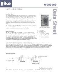
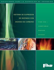
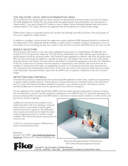
A Fike CO 2 system protecting an EDM process is<br />
shown in the illustration below.<br />
References:<br />
Sommer, Carl. (2000). Non-Traditional <strong>Machining</strong><br />
Handbook. Houston, TX: Advance Publishing, Inc.<br />
R<br />
“Electronic <strong>Discharge</strong> Machine” Protected by a<br />
Fike Carbon Dioxide Suppression System<br />
Copyright © Fike Corporation All Rights Reserved.<br />
Form No. CDAP003 May, 2008 Specifi cations are subject to change without notice.