Photoelectric Smoke Detector P.1.18.01-4 - ORR Protection
Photoelectric Smoke Detector P.1.18.01-4 - ORR Protection
Photoelectric Smoke Detector P.1.18.01-4 - ORR Protection
- No tags were found...

You also want an ePaper? Increase the reach of your titles
YUMPU automatically turns print PDFs into web optimized ePapers that Google loves.
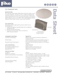
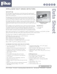
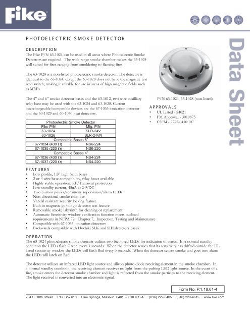
PHOTOELECTRIC SMOKE DETECTORDESCRIPTIONThe Fike P/N 63-1024 can be used in all areas where <strong>Photoelectric</strong> <strong>Smoke</strong><strong>Detector</strong>s are required. The wide range smoke chamber makes the 63-1024well suited for fires ranging from smoldering to flaming fires.The 63-1028 is a non-listed photoelectric smoke detector. The detector isidentical to the 63-1024, except the 63-1028 does not have the magnetic testreed switch, making it suitable for use in areas of high magnetic fields suchas MRI’s.The 4” and 6” smoke detector bases and the 63-1012, two wire auxilliaryrelay base may be used with the 63-1024 and 63-1028. Currentinterchangeable/compatible devices are the 67-1033 ionization detectorand the 60-1029 and 60-1030 heat detectors.<strong>Photoelectric</strong> <strong>Smoke</strong> <strong>Detector</strong>Fike P/NMfg. P/N63-1024 SLR-24V63-1028 SLR-24VNCompatible Bases 6”67-1034 (430 Ω) NS6-22467-1035 (220 Ω) NS6-220Compatible Bases 4”67-1036 (430 Ω) NS4-22467-1037 (220 Ω) NS4-220P/N 63-1024, 63-1028 (non-listed)APPROVALS• UL Listed - S4021• FM Approval - 3010873• CSFM - 7272-0410:107FEATURES• Low profile, 1.8” high (with base)• 2 or 4 wire base compatibility, relay bases available• Highly stable operation, RF/Transient protection• Low standby current, 45uA at 24VDC• Two built-in power/sensitivity supervision/alarm LEDs• Non-directional smoke chamber• Vandal resistant security locking feature• Built-in magnetic go/no go detector test feature• Removable smoke labyrinth for cleaning or replacement• Automatic Sensitivity window verification function meets outlinedrequirements in NFPA 72, Chapter 7, Inspection, Testing and Maintenance• Compatible with 67-1033 ionization detectors• Backwards compatible with Hochiki SLK and SIH detectors basesOPERATIONThe 63-1024 photoelectric smoke detector utilizes two bicolored LEDs for indication of status. In a normal standbycondition the LEDs flash Green every 3 seconds. When the detector senses that its sensitivity has drifted outside the ULlisted sensitivity window the LEDs will flash Red every 3 seconds. When the detector senses smoke and goes into alarmthe LEDs will latch on Red.The detector utilizes an infrared LED light source and silicon photo diode receiving element in the smoke chamber. Ina normal standby condition, the receiving element receives no light from the pulsing LED light source. In the event of afire, smoke enters the detector smoke chamber and light is reflected from the smoke particles to the receiving element.The light received is converted into an electronic signal.Form No. <strong>P.1.18.01</strong>-4704 S. 10th Street · P.O. Box 610 · Blue Springs, Missouri 64013-0610 U.S.A. · (816) 229-3405 · (816) 229-4615 · www.fi ke.com
OPERATION cont.Signals are processed and compared to a reference level, and when two consecutive signals exceeding the reference levelare received within a specified period of time, the time delay circuit triggers the SCR switch to activate the alarm signal.The LEDs light continuously during the alarm period.63-1024 Sensitivity Test FeatureThe 63-1024 <strong>Photoelectric</strong> <strong>Smoke</strong> <strong>Detector</strong> has a built-in automatic sensitivity test feature.1. In normal condition, both LED’s flash green.2. When the sensitivity drifts outside of its sensitivity limits, both LED’s flash red.3. In the alarm state both LED’s are red continuously.4. When the sensitivity drifts outside of its sensitivity limits and both LED’s flash red, the device needs to be cleanedor returned to the factory for cleaning. Refer to Hochiki Technical Bulletin HA-97 for cleaning informationSpacingWhen spacing smoke detectors following the guidelines listed in NFPA 72, base the number and location of sensors onan engineering survey of the area to be detected. The <strong>Photoelectric</strong> smoke detectors cover 900 sq. ft.SPECIFICATIONSThe contractor shall furnish and install where indicated on the plans, Fike 63-1024 photoelectric smoke detectors. Thecombination detector head and twist-lock base shall be UL listed compatible with a UL listed fire alarm panel.The base shall permit direct interchange with Fike 63-1025 combination photoelectric/heat detector, 67-1033 ionizationtype smoke detector and/or 60-1029/60-1030 fixed temperature/rate-of-rise heat detectors. The base shall be appropriatetwist-lock base. In the event of partial or complete retrofit, the 63-1024 maybe used in conjunction with, or as areplacement for, Fike detectors (63-1007, 63-1016 and the 67-1016) on most HSB and HSC base applications.The smoke detector shall have two flashing status LEDs for visual supervision. When the detector is in standby conditionthe LEDs will flash Green. When the detector is outside the UL listed sensitivity window the LEDs will flash Red. Whenthe detector is actuated, the flashing LEDs will latch Red. The detector may be reset by actuating the control panel resetswitch.The sensitivity of the detector shall be capable of being measured. It shall be possible to perform a functional test of thedetector without the need of generating smoke. The sensitivity of the detector shall be monitored automatically andcontinuously to verify that it is operating within the Listed sensitivity range.To facilitate installation, the detector shall be non-polarized. Voltage and RF transient suppression techniques shall beemployed to minimize false alarm potential. Auxiliary SPDT relays shall be installed where indicated.The vandal-resistant, security locking feature shall be used in those areas as indicated on the drawing. The locking featureshall be field removable when not required.Light SourceRated VoltageWorking VoltageMaximum VoltageSupervisory CurrentSurge CurrentAlarm CurrentAir Velocity RangeAmbient TemperatureColor & Case MaterialSensitivity Test FeatureGaAlAs Infrared Emitting Diode17.7 - 30.0 VDC15.0 - 33.0 VDC42 VDC45μA @ 24 VDC160μA max. @ 24 VDC150μA max. @ 24 VDC0-4000 fpm32°F to 120°F (0°C to 49°C)Bone PC/ABS BlendAutomatic Sensitivity window verification testRCopyright © Fike Corporation All Rights Reserved.Form No. <strong>P.1.18.01</strong>-4 May, 2007 Specifi cations are subject to change without notice.