- Page 1 and 2:
A L T R A I N D U S T R I A L M O T
- Page 3 and 4:
Table Of Contents Stock Altered and
- Page 5 and 6:
Modified Stock Gearing With thousan
- Page 7 and 8:
Custom Gearing “Request For Quota
- Page 9 and 10:
Custom Gearing Capabilities Gear Ty
- Page 11 and 12:
Gear Selection Stock Gears Pressure
- Page 13 and 14:
Product Selection / Reference Guide
- Page 15 and 16:
Product Selection / Reference Guide
- Page 17 and 18:
Product Selection / Reference Guide
- Page 19 and 20:
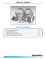
Boston Gear Helical Gears ■ Paral
- Page 21 and 22:
Boston Gear Worms and Worm Gears
- Page 23 and 24:
Spur Gears 48 and 32 Diametral Pitc
- Page 25 and 26:
A Spur Gears 24 and 20 Diametral Pi
- Page 27 and 28:
Spur Gears 16 and 12 Diametral Pitc
- Page 29 and 30:
Spur Gears 10 and 8 Diametral Pitch
- Page 31 and 32:
Spur Gears 6 and 5 Diametral Pitch
- Page 33 and 34:
Change Gears 20 Diametral Pitch (St
- Page 35 and 36:
Change Gears 12 Diametral Pitch (St
- Page 37 and 38:
Change Gears 8 Diametral Pitch (Ste
- Page 39 and 40:
Drawn Pinion Wire 48, 32 and 24 Dia
- Page 41 and 42:
Internal Gears 48 through 16 Diamet
- Page 43 and 44:
Spur Gears 48 Diametral Pitch (Delr
- Page 45 and 46:
Spur Gears 32 Diametral Pitch (Delr
- Page 47 and 48:
Spur Gears 24 and 20 Diametral Pitc
- Page 49 and 50:
Spur Gears 12 and 10 Diametral Pitc
- Page 51 and 52:
Spur Gears 6 and 5 Diametral Pitch
- Page 53 and 54:
Internal Gears 64 through 24 Diamet
- Page 55 and 56:
Spur Gears Approximate Horsepower a
- Page 57 and 58:
Spur Gears Approximate Horsepower a
- Page 59 and 60:
Spur Gears Approximate Horsepower a
- Page 61 and 62:
Spur Gears Approximate Horsepower a
- Page 63 and 64:
Spur Gears Approximate Horsepower a
- Page 65 and 66:
Spur Gears Approximate Horsepower a
- Page 67 and 68:
Spur Gears Approximate Horsepower a
- Page 69 and 70:
Helical Gears 24 through 10 Transve
- Page 71 and 72:
Helical Gears Boston standard stock
- Page 73 and 74:
Helical Gears Approximate Horsepowe
- Page 75 and 76:
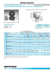
Miter Gears 48 through 20 Diametral
- Page 77 and 78:
Miter Gears 8 through 4 Diametral P
- Page 79 and 80:
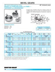
Bevel Gears 48 through 20 Diametral
- Page 81 and 82:
Bevel Gears 12 and 10 Diametral Pit
- Page 83 and 84:
Spiral Bevel Gears 30 through 8 Dia
- Page 85 and 86:
Miter Gears Steel & Iron - Straight
- Page 87 and 88:
Bevel Gears Steel & Iron - Straight
- Page 89 and 90:
Notes C 84 Boston Gear 800-825-6544
- Page 91 and 92:
Worms & Worm Gears 48 Diametral Pit
- Page 93 and 94:
Worms & Worm Gears 24 Diametral Pit
- Page 95 and 96:
Worms & Worm Gears 12 Diametral Pit
- Page 97 and 98:
Worms & Worm Gears 8 Diametral Pitc
- Page 99 and 100:
Worms & Worm Gears 4 Diametral Pitc
- Page 101 and 102:
Worms & Worm Gears Boston worms and
- Page 103 and 104:
Worms & Worm Gears Steel-Hardened,
- Page 105 and 106:
Shaft Couplings FC Series Insert (3
- Page 107 and 108:
Shaft Couplings BF Series Bost-Flex
- Page 109 and 110:
Shaft Couplings SCC Series Clamping
- Page 111 and 112:
Shaft Couplings FCP Series Sleeve T
- Page 113 and 114:
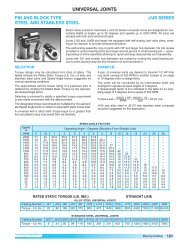
Universal Joints J/JS Series Bored
- Page 115 and 116:
Universal Joints UJNS/UJNL Series B
- Page 117 and 118:
Universal Joints JP Series Single a
- Page 119 and 120:
Setscrew Collars SC/SSC Series Stee
- Page 121 and 122:
Clamping Collars CSC/CSSC/CASC Seri
- Page 123 and 124:
Thrust Washers Steel and Stainless
- Page 125 and 126:
Grooved Pulleys G1200 Round Belt Ty
- Page 127 and 128:
Miniature Timing Belts and Pulleys
- Page 129 and 130:
Miniature HTD ® Timing Belts 3M Se
- Page 131 and 132: Timing Belt Pulleys PA Series For 9
- Page 133 and 134: Timing Belt Pulleys PLB Series For
- Page 135 and 136: Miniature HTD ® Timing Belts 5M Se
- Page 137 and 138: Timing Belt Pulleys PA Series For 1
- Page 139 and 140: Timing Belt Pulleys PLB Series For
- Page 141 and 142: BOST-BRONZ Oil-Impregnated Sintered
- Page 143 and 144: BOST-BRONZ Oil-Impregnated Sintered
- Page 145 and 146: BOST-BRONZ Oil-Impregnated Sintered
- Page 147 and 148: BOST-BRONZ Oil-Impregnated Sintered
- Page 149 and 150: BOST-BRONZ Oil-Impregnated Sintered
- Page 151 and 152: BEAR-N-BRONZE 660 Cast Bronze Beari
- Page 153 and 154: BEAR-N-BRONZE 660 Cast Bronze Beari
- Page 155 and 156: BEAR-N-BRONZE 660 Cast Bronze Beari
- Page 157 and 158: BEAR-N-BRONZE 660 Cast Bronze Beari
- Page 159 and 160: Bronze Bearing Emergency Banks SAVE
- Page 161 and 162: BOStonE F-1 Glass Filled Teflon Bea
- Page 163 and 164: RULON ® 641 Bearings Boston Gear
- Page 165 and 166: BOStonE Molded Plastic Bearings F B
- Page 167 and 168: BOStonE Molded Plastic Bearings Rol
- Page 169 and 170: F BOStonE Molded Plastic Bearings R
- Page 171 and 172: BOStonE Molded Plastic Bearings Rol
- Page 173 and 174: BOStonE Molded Plastic Bearings Rol
- Page 175 and 176: BOStonE Molded Plastic Bearings Gui
- Page 177 and 178: BOStonE Molded Nylon Bearings Plain
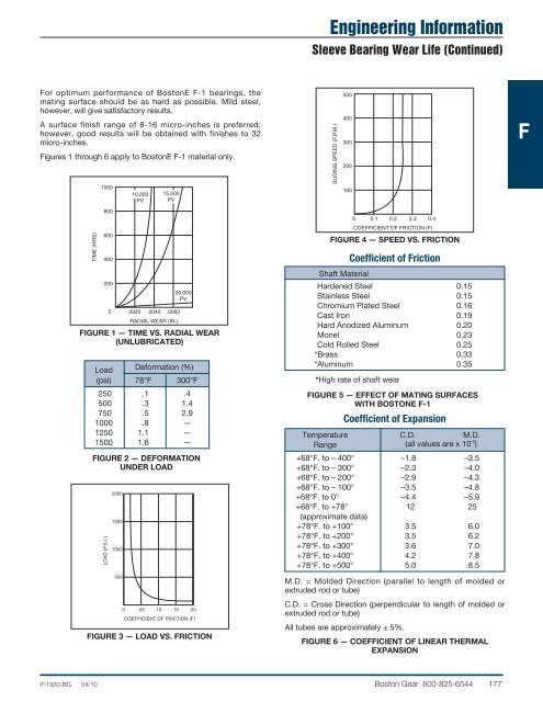
- Page 179 and 180: Engineering Information Sleeve Bear
- Page 181: Engineering Information Sleeve Bear
- Page 185 and 186: Engineering Information Shaft Clear
- Page 187 and 188: Engineering Information Machining F
- Page 189 and 190: Anti-Friction Bearings Ball Bearing
- Page 191 and 192: F Anti-Friction Bearings 1600 Serie
- Page 193 and 194: Anti-Friction Bearings 7600 Series
- Page 195 and 196: Anti-Friction Bearings 3000 Series
- Page 197 and 198: Anti-Friction Bearings Flanged 400F
- Page 199 and 200: Anti-Friction Bearings 600 Series T
- Page 201 and 202: Anti-Friction Bearings 2100 Series
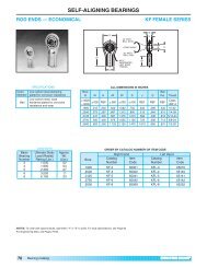
- Page 203 and 204: Self-Aligning Bearings KF Female Se
- Page 205 and 206: Self-Aligning Bearings CMHD Male/CF
- Page 207 and 208: Self-Aligning Bearings HME Male/HFE
- Page 209 and 210: Self-Aligning Bearings LHA-LHB-LHSS
- Page 211 and 212: Self-Aligning Bearings LS/LSS Serie
- Page 213 and 214: Engineering Information Engineering
- Page 215 and 216: Engineering Information Engineering
- Page 217 and 218: Mounted Bearings Replacement Bearin
- Page 219 and 220: Mounted Bearings Replacement Bearin
- Page 221 and 222: Mounted Ball Bearings PS Series Pre
- Page 223 and 224: Mounted Ball Bearings L/H Series Pi
- Page 225 and 226: Mounted Ball Bearings SL/SH Series
- Page 227 and 228: Mounted Ball Bearings MB Series Pil
- Page 229 and 230: Mounted Ball Bearings XL2/XL3 Serie
- Page 231 and 232: Mounted Ball Bearings F/T Series Fl
- Page 233 and 234:
Mounted Ball Bearings SF/ST Series
- Page 235 and 236:
Mounted Ball Bearings MBP Series Pi
- Page 237 and 238:
Mounted Bearings TU Series Take-Up
- Page 239 and 240:
Engineering Information Analysis of
- Page 241 and 242:
Engineering Information Mounted Bal
- Page 243 and 244:
Engineering Information Application
- Page 245 and 246:
Notes F 240 Boston Gear 800-825-654
- Page 247 and 248:
Roller Chains Description of Roller
- Page 249 and 250:
Roller Chains ANSI Standard Double,
- Page 251 and 252:
Engineering Information Conveyor Ch
- Page 253 and 254:
Engineering Information Conveyor Ch
- Page 255 and 256:
Notes G 250 Boston Gear 800-825-654
- Page 257 and 258:
Roller Chains Hollow Pin Single and
- Page 259 and 260:
Ladder Chain Steel-Stainless Steel-
- Page 261 and 262:
Chain Pullers The Boston Chain Pull
- Page 263 and 264:
Chain Drives Roller Chain Sprockets
- Page 265 and 266:
Roller Chain Drives Horsepower Rati
- Page 267 and 268:
Roller Chain Drives Horsepower Rati
- Page 269 and 270:
Roller Chain Drives Selection SPEED
- Page 271 and 272:
H Miniature Chain Sprockets Single
- Page 273 and 274:
Roller Chain Sprockets Single Stran
- Page 275 and 276:
H Roller Chain Sprockets Single Str
- Page 277 and 278:
Roller Chain Sprockets Single Stran
- Page 279 and 280:
H Roller Chain Sprockets Single Str
- Page 281 and 282:
H Roller Chain Sprockets Single Str
- Page 283 and 284:
Roller Chain Sprockets Single Stran
- Page 285 and 286:
Roller Chain Sprockets Single Stran
- Page 287 and 288:
Roller Chain Sprockets Single Stran
- Page 289 and 290:
Roller Chain Sprockets Single Stran
- Page 291 and 292:
Roller Chain Sprockets Single Stran
- Page 293 and 294:
Roller Chain Sprockets Single Stran
- Page 295 and 296:
Block Chain Sprockets Type B Single
- Page 297 and 298:
Ladder Chain Sprockets Type B Singl
- Page 299 and 300:
Roller Chain Drive Tensioners Type
- Page 301 and 302:
Roller Chain Drive Tensioners Type
- Page 303 and 304:
Engineering Information Spur Gears
- Page 305 and 306:
Engineering Information Spur Gears
- Page 307 and 308:
I Engineering Information Spur Gear
- Page 309 and 310:
Engineering Information Helical Gea
- Page 311 and 312:
Engineering Information Helical Gea
- Page 313 and 314:
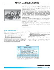
Engineering Information Miter and B
- Page 315 and 316:
Engineering Information Worms and W
- Page 317 and 318:
Engineering Information Couplings A
- Page 319 and 320:
Engineering Information General I M
- Page 321 and 322:
Engineering Information Sprockets I
- Page 323 and 324:
Engineering Information Sprocket Di
- Page 325 and 326:
Engineering Information Temperature
- Page 327 and 328:
Engineering Information Metric Conv
- Page 329 and 330:
Engineering Information Application
- Page 331 and 332:
Index to Catalog Numbers Catalog Nu
- Page 333 and 334:
Index to Catalog Numbers I Catalog
- Page 335:
Altra Industrial Motion All Custome