Modified Stock Gearing - Boston Gear
Modified Stock Gearing - Boston Gear
Modified Stock Gearing - Boston Gear

Create successful ePaper yourself
Turn your PDF publications into a flip-book with our unique Google optimized e-Paper software.
Engineering Information<br />
Analysis of Radial Bearing Loads for Unmounted and Mounted Rolling Elements<br />
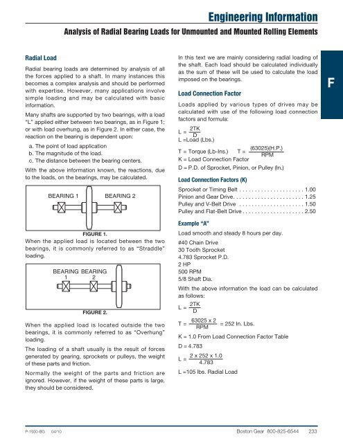
Radial Load<br />
Radial bearing loads are determined by analysis of all<br />
the forces applied to a shaft. In many instances this<br />
becomes a complex analysis and should be performed<br />
with expertise. However, many applications involve<br />
simple loading and may be calculated with basic<br />
information.<br />
Many shafts are supported by two bearings, with a load<br />
“L” applied either between two bearings, as in Figure 1;<br />
or with load overhung, as in Figure 2. In either case, the<br />
reaction on the bearing is dependent upon:<br />
a. The point of load application<br />
b. The magnitude of the load.<br />
c. The distance between the bearing centers.<br />
With the above information known, the reactions, due<br />
to the loads, on the bearings, may be calculated.<br />
BEARING 1 BEARING 2<br />
FIGURE 1.<br />
When the applied load is located between the two<br />
bearings, it is commonly referred to as “Straddle”<br />
loading.<br />
BEARING<br />
1<br />
BEARING<br />
2<br />
FIGURE 2.<br />
When the applied load is located outside the two<br />
bearings, it is commonly referred to as “Overhung”<br />
loading.<br />
The loading of a shaft usually is the result of forces<br />
generated by gearing, sprockets or pulleys, the weight<br />
of these parts and friction.<br />
Normally the weight of the parts and friction are<br />
ignored. However, if the weight of these parts is large,<br />
they should be considered.<br />
In this text we are mainly considering radial loading of<br />
the shaft. Each load should be calculated individually<br />
as the sum of these will be used to calculate the load<br />
imposed on the bearings.<br />
Load Connection Factor<br />
Loads applied by various types of drives may be<br />
calculated with use of the following load connection<br />
factors and formula:<br />
2TK<br />
L= D<br />
L =Load (Lbs.)<br />
(63025)(H.P.)<br />
T = Torque (Lb-Ins.) T =<br />
RPM<br />
K = Load Connection Factor<br />
D = P.D. of Sprocket, Pinion, or Pulley (In.)<br />
Load Connection Factors (K)<br />
Sprocket or Timing Belt . . . . . . . . . . . . . . . . . . . . . 1.00<br />
Pinion and <strong>Gear</strong> Drive. . . . . . . . . . . . . . . . . . . . . . . 1.25<br />
Pulley and V-Belt Drive . . . . . . . . . . . . . . . . . . . . . 1.50<br />
Pulley and Flat-Belt Drive . . . . . . . . . . . . . . . . . . . . 2.50<br />
Example “A”<br />
Load smooth and steady 8 hours per day.<br />
#40 Chain Drive<br />
30 Tooth Sprocket<br />
4.783 Sprocket P.D.<br />
2 HP<br />
500 RPM<br />
5/8 Shaft Dia.<br />
With the above information the load can be calculated<br />
as follows:<br />
2TK<br />
L= D<br />
63025 x 2<br />
T =<br />
= 252 In. Lbs.<br />
RPM<br />
K = 1.0 From Load Connection Factor Table<br />
D = 4.783<br />
2 x 252 x 1.0<br />
L=<br />
4.783<br />
L =105 lbs. Radial Load<br />
F<br />
P-1930-BG 04/10 <strong>Boston</strong> <strong>Gear</strong> 800-825-6544 233