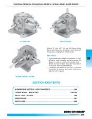
Modified Stock Gearing - Boston Gear
Modified Stock Gearing - Boston Gear
Modified Stock Gearing - Boston Gear

You also want an ePaper? Increase the reach of your titles
YUMPU automatically turns print PDFs into web optimized ePapers that Google loves.
Engineering Information<br />
Miter and Bevel Bears<br />
Tooth Strength (Straight Tooth)<br />
The beam strength of Miter and Bevel gears (straight tooth)<br />
may be calculated using the Lewis Formula revised to<br />
compensate for the differences between Spur and Bevel gears.<br />
Several factors are often combined to make allowance for the<br />
tooth taper and the normal overhung mounting of Bevel gears.<br />
SFY 600<br />
W= .75<br />
P 600 + V<br />
W = Tooth Load, Lbs. (along the Pitch Line)<br />
S = Safe Material Stress (static) Lbs. per Sq. In. (Table 1)<br />
F = Face Width, In.<br />
Y = Tooth Form Factor (Table I)<br />
P = Diametral Pitch<br />
D = Pitch Diameter<br />
V = Pitch Line Velocity, Ft. per Min. = .262 x D x RPM<br />
TABLE I VALUES OF SAFE STATIC STRESS (s)<br />
Material<br />
(s) Lb. per Sq. In.<br />
Plastic . . . . . . . . . . . . . . . . . . . . . . . . . . . . . . . . . . . . . . . . . . 5000<br />
Bronze . . . . . . . . . . . . . . . . . . . . . . . . . . . . . . . . . . . . . . . . . 10000<br />
Cast Iron . . . . . . . . . . . . . . . . . . . . . . . . . . . . . . . . . . . . . . . . 12000<br />
{.20 Carbon (Untreated) . . . . . . . . . . . . . . . . . . . . . . 20000<br />
.20 Carbon (Case-hardened) . . . . . . . . . . . . . . . . . . 25000<br />
Steel .40 Carbon (Untreated) . . . . . . . . . . . . . . . . . . . . . . 25000<br />
.40 Carbon (Heat-treated) . . . . . . . . . . . . . . . . . . . . 30000<br />
.40 C. Alloy (Heat-treated) . . . . . . . . . . . . . . . . . . . . 40000<br />
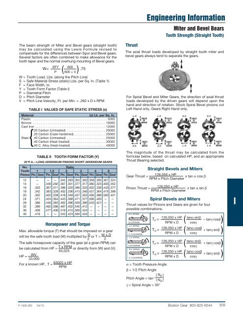
Thrust<br />
The axial thrust loads developed by straight tooth miter and<br />
bevel gears always tend to separate the gears.<br />
For Spiral Bevel and Miter <strong>Gear</strong>s, the direction of axial thrust<br />
loads developed by the driven gears will depend upon the<br />
hand and direction of rotation. <strong>Stock</strong> Spiral Bevel pinions cut<br />
Left Hand only, <strong>Gear</strong>s Right Hand only.<br />
TABLE II TOOTH FORM FACTOR (Y)<br />
20°P.A.—LONG ADDENDUM PINIONS SHORT ADDENDUM GEARS<br />
No.<br />
Ratio<br />
Teeth 1 1.5 2 3 4 6<br />
Pinion Pin. <strong>Gear</strong> Pin. <strong>Gear</strong> Pin. <strong>Gear</strong> Pin. <strong>Gear</strong> Pin. <strong>Gear</strong> Pin. <strong>Gear</strong><br />
12 — — — .345 .283 .355 .302 .358 .305 .361 .324<br />
14 — .349 .292 .367 .301 .377 .317 .380 .323 .405 .352<br />
16 .333 .367 .311 .386 .320 .396 .333 .402 .339 .443 .377<br />
18 .342 .383 .328 .402 .336 .415 .346 .427 .364 .474 .399<br />
20 .352 .402 .339 .418 .349 .427 .355 .456 .386 .500 .421<br />
24 .371 .424 .364 .443 .368 .471 .377 .506 .405 — —<br />
28 .386 .446 .383 .462 .386 .509 .396 .543 .421 — —<br />
32 .399 .462 .396 .487 .402 .540 .412 — — — —<br />
36 .408 .477 .408 .518 .415 .569 .424 — — — —<br />
40 .418 — — .543 .424 .594 .434 — — — — R.H. SPIRAL<br />
Horsepower and Torque<br />
Max. allowable torque (T) that should be imposed on a gear<br />
will be the safe tooth load (W) multiplied by D or T = W x D<br />
2 2<br />
The safe horsepower capacity of the gear (at a given RPM) can<br />
be calculated from HP = T x RPM or directly from (W) and (V);<br />
HP =<br />
WV<br />
33,000<br />
For a known HP, T =<br />
63,025<br />
63025 x HP<br />
RPM<br />
The magnitude of the thrust may be calculated from the<br />
formulae below, based on calculated HP, and an appropriate<br />
Thrust Bearing selected.<br />
Straight Bevels and Miters<br />
<strong>Gear</strong> Thrust =<br />
126,050 x HP<br />
x tan α cos β<br />
RPM x Pitch Diameter<br />
Pinion Thrust =<br />
126,050 x HP<br />
x tan α sin β<br />
RPM x Pitch Diameter<br />
Spiral Bevels and Miters<br />
Thrust values for Pinions and <strong>Gear</strong>s are given for four<br />
possible combinations.<br />
CLOCKWISE<br />
L.H. SPIRAL<br />
C. CLOCKWISE<br />
L.H. SPIRAL<br />
CLOCKWISE<br />
R.H. SPIRAL<br />
C. CLOCKWISE<br />
T P =<br />
T G =<br />
T P =<br />
T G =<br />
α = Tooth Pressure Angle<br />
β = 1/2 Pitch Angle<br />
Pitch Angle = tan ( N -1 P<br />
N G<br />
)<br />
γ = Spiral Angle = 35°<br />
126,050 x HP<br />
RPM x D<br />
126,050 x HP<br />
RPM x D<br />
126,050 x HP<br />
RPM x D<br />
126,050 x HP<br />
RPM x D<br />
tanα sinβ – tanγ cosβ<br />
cosγ<br />
tanα cosβ + tanγ sinβ<br />
cosγ<br />
tanα sinβ + tanγ cosβ<br />
cosγ<br />
tanα cosβ + tanγ sinβ<br />
cosγ<br />
I<br />
P-1930-BG 04/10 <strong>Boston</strong> <strong>Gear</strong> 800-825-6544 309