Modified Stock Gearing - Boston Gear
Modified Stock Gearing - Boston Gear
Modified Stock Gearing - Boston Gear

Create successful ePaper yourself
Turn your PDF publications into a flip-book with our unique Google optimized e-Paper software.
Engineering Information<br />
Sprockets<br />
I<br />
Alterations<br />
<strong>Boston</strong> <strong>Gear</strong> Service Centers are equipped to alter catalog<br />
sprockets (rebore, keyway, setscrew, etc.). For customers,<br />
choosing to make their own alterations, the guidelines listed<br />
below should be beneficial. Alterations to hardened gears<br />
should not be made without consultation with factory.<br />
In setting up for reboring the most important consideration is<br />
to preserve the accuracy of concentricity and lateral runout<br />
provided in the original product. There are several methods for<br />
accomplishing this. One procedure is: mount the part on an<br />
arbor, machine hub diameter to provide a true running<br />
surface, remove from arbor and chuck on the hub diameter,<br />
check face and bore runout prior to reboring. As a basic rule<br />
of thumb, the maximum bore should not exceed 60% of the<br />
Hub Diameter and depending on Key size should be checked<br />
for minimum wall thickness. A minimum of one setscrew<br />
diameter over a keyway is considered adequate.<br />
<strong>Boston</strong> <strong>Gear</strong> offers a service for hardening stock sprockets.<br />
This added treatment can provide increased horsepower<br />
capacity with resultant longer life and/or reduction in size and<br />
weight.<br />
Customers wishing to do the hardening operation should refer<br />
to “Materials” below for information.<br />
Materials<br />
Plastic<br />
Plastic sprockets listed are molded from Nylatron GS.<br />
Steel<br />
Type B one-piece sprockets are furnished in a free-machining,<br />
low carbon steel.<br />
Plate sprockets (Type A) and two-piece construction (Type B)<br />
are made of low carbon steel (basically AISI 1020).<br />
1/4” pitch (Type B) up to 20 teeth is furnished from sintered<br />
metal powder conforming to ASTM-B-426-70 Grade 1, Type III<br />
with hardness of RB60 MIN.<br />
Stainless Steel<br />
1/4, 3/8 and 1/2” Pitches stock bore, single strand are<br />
furnished from 303 free-machining Stainless Steel.<br />
Cast Iron<br />
Block Chain Sprockets are furnished in Cast Iron for 9 through<br />
12 teeth, which conforms to ASTM-A48-Class 30 Cast Iron,<br />
providing a fine-grained material with good wear resistant<br />
properties.<br />
STANDARD KEYWAYS AND SETSCREWS<br />
Diameter of Hole<br />
Standard Keyway Recommended<br />
W D Setscrew<br />
5/16 to 7/16 “ 3/32” 3/64” 10–32<br />
1/2 to 9/16 1/8 1/16 1/4–20<br />
5/8 to 7/8 3/16 3/32 5/16–18<br />
15/16 to 1-1/4 1/4 1/8 3/8–16<br />
1-5/16 to 1-3/8 5/16 5/32 7/16–14<br />
1-7/16 to 1-3/4 3/8 3/16 1/2–13<br />
1-13/16 to 2-1/4 1/2 1/4 9/16–12<br />
2-5/16 to 2-3/4 5/8 5/16 5/8–11<br />
2-13/16 to 3-1/4 3/4 3/8 3/4–10<br />
3-5/16 to 3-3/4 7/8 7/16 7/8–9<br />
3-13/16 to 4-1/2 1 1/2 1–8<br />
4-9/16 to 5-1/2 1-1/4 7/16 1-1/8–7<br />
5-9/16 to 6-1/2 1-1/2 1/2 1-1/4–6<br />
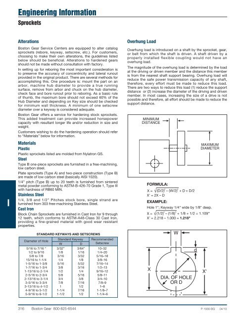
Overhung Load<br />
Overhung load is introduced on a shaft by the sprocket, gear,<br />
or belt from which the shaft is driven. A shaft driven by a<br />
properly installed flexible coupling would not have an<br />
overhung load.<br />
The magnitude of the overhung load is determined by the load<br />
at the driving or driven member and the distance this member<br />
is from the nearest shaft support bearing. Overhung load will<br />
reduce the safe power transmission capacity of any shaft,<br />
therefore, every effort must be made to reduce this load.<br />
There are two ways to reduce this load (1) reduce the support<br />
distance or (2) increase the diameter of the driving and driven<br />
member. In most cases, increasing the size of a drive is not<br />
possible and therefore, all effort should be made to reduce the<br />
support distance.<br />
MINIMUM<br />
DISTANCE<br />
FORMULA:<br />
X<br />
W<br />
DIA. OF HOLE<br />
OR D<br />
d<br />
MAXIMUM<br />
DIAMETER<br />
X' = 2X – D<br />
EXAMPLE:<br />
Hole 1"; Keyway 1/4" wide by 1/8" deep.<br />
X' = 2.218 – 1.000 = 1.218"<br />
X'<br />
316 <strong>Boston</strong> <strong>Gear</strong> 800-825-6544 P-1930-BG 04/10