Modified Stock Gearing - Boston Gear
Modified Stock Gearing - Boston Gear
Modified Stock Gearing - Boston Gear

You also want an ePaper? Increase the reach of your titles
YUMPU automatically turns print PDFs into web optimized ePapers that Google loves.
I<br />
Engineering Information<br />
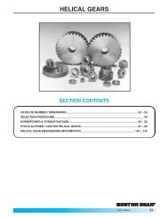
Spur <strong>Gear</strong>s<br />
Backlash<br />
<strong>Stock</strong> spur gears are cut to operate at standard center<br />
distances. The standard center distance being defined by:<br />
Standard Center Distance =<br />
Pinion PD + <strong>Gear</strong> PD<br />
2<br />
When mounted at this center distance, stock spur gears will<br />
have the following average backlash:<br />
Diametral Backlash Diametral Backlash<br />
Pitch (Inches) Pitch (Inches)<br />
3 .013 8-9 .005<br />
4 .010 10-13 .004<br />
5 .008 14-32 .003<br />
6 .007 33-64 .0025<br />
7 .006<br />
An increase or decrease in center distance will cause an<br />
increase or decrease in backlash.<br />
Since, in practice, some deviation from the theoretical<br />
standard center distance is inevitable and will alter the<br />
backlash, such deviation should be as small as possible. For<br />
most applications, it would be acceptable to limit the<br />
deviation to an increase over the nominal center distance of<br />
one half the average backlash. Varying the center distance<br />
may afford a practical means of varying the backlash to a<br />
limited extent.<br />
The approximate relationship between center distance and<br />
backlash change of 14-1/2° and 20° pressure angle gears is<br />
shown below:<br />
For 14-1/2°–Change in Center Distance = 1.933 x Change in Backlash<br />
For 20° –Change in Center Distance = 1.374 x Change in Backlash<br />
From this, it is apparent that a given change in center<br />
distance, 14-1/2° gears will have a smaller change in<br />
backlash than 20° gears. This fact should be considered in<br />
cases where backlash is critical.<br />
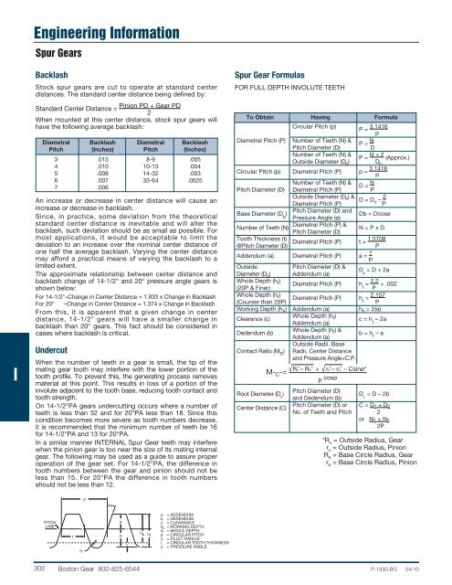
Undercut<br />
When the number of teeth in a gear is small, the tip of the<br />
mating gear tooth may interfere with the lower portion of the<br />
tooth profile. To prevent this, the generating process removes<br />
material at this point. This results in loss of a portion of the<br />
involute adjacent to the tooth base, reducing tooth contact and<br />
tooth strength.<br />
On 14-1/2°PA gears undercutting occurs where a number of<br />
teeth is less than 32 and for 20°PA less than 18. Since this<br />
condition becomes more severe as tooth numbers decrease,<br />
it is recommended that the minimum number of teeth be 16<br />
for 14-1/2°PA and 13 for 20°PA.<br />
In a similar manner INTERNAL Spur <strong>Gear</strong> teeth may interfere<br />
when the pinion gear is too near the size of its mating internal<br />
gear. The following may be used as a guide to assure proper<br />
operation of the gear set. For 14-1/2°PA, the difference in<br />
tooth numbers between the gear and pinion should not be<br />
less than 15. For 20°PA the difference in tooth numbers<br />
should not be less than 12.<br />
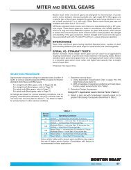
Spur <strong>Gear</strong> Formulas<br />
FOR FULL DEPTH INVOLUTE TEETH<br />
To Obtain Having Formula<br />
Circular Pitch (p)<br />
P = 3.1416<br />
p<br />
Diametral Pitch (P) Number of Teeth (N) &<br />
P = N<br />
Pitch Diameter (D)<br />
D<br />
Number of Teeth (N) &<br />
Outside Diameter (D o )<br />
P = N + 2 (Approx.)<br />
D o<br />
Circular Pitch (p) Diametral Pitch (P) p = 3.1416<br />
P<br />
Number of Teeth (N) &<br />
D = N<br />
Pitch Diameter (D) Diametral Pitch (P) P<br />
Outside Diameter (D o ) & D = Do – 2<br />
Diametral Pitch (P)<br />
P<br />
Base Diameter (D b<br />
)<br />
Pitch Diameter (D) and<br />
Pressure Angle (ø)<br />
Db = Dcosø<br />
Number of Teeth (N)<br />
Diametral Pitch (P) &<br />
Pitch Diameter (D)<br />
N = P x D<br />
Tooth Thickness (t)<br />
Diametral Pitch (P) t = 1.5708<br />
@Pitch Diameter (D)<br />
P<br />
Addendum (a) Diametral Pitch (P) a = 1 P<br />
Outside<br />
Pitch Diameter (D) &<br />
Diameter (D o ) Addendum (a)<br />
D o<br />
= D + 2a<br />
Whole Depth (h t )<br />
Diametral Pitch (P) h t<br />
= 2.2 + .002<br />
(20P & Finer) P<br />
Whole Depth (h t )<br />
Diametral Pitch (P) h t<br />
= 2.157<br />
(Courser than 20P)<br />
P<br />
Working Depth (h k ) Addendum (a) h k = 2(a)<br />
Clearance (c)<br />
Whole Depth (h t )<br />
Addendum (a)<br />
c = h t<br />
– 2a<br />
Dedendum (b)<br />
Whole Depth (h t ) &<br />
Addendum (a)<br />
b = h t<br />
– a<br />
Outside Radii, Base<br />
Contact Ratio (M c ) Radii, Center Distance<br />
and Pressure Angle+C.P.<br />
2<br />
2 2<br />
ro – rb<br />
M- C -= Ro – Rb + p cosø<br />
2<br />
– Csinø*<br />
Root Diameter (D r<br />
)<br />
Pitch Diameter (D)<br />
D r<br />
= D – 2b<br />
and Dedendum (b)<br />
Center Distance (C)<br />
Pitch Diameter (D) or C = D 1 + D 2<br />
No. of Teeth and Pitch 2<br />
or N 1 + N 2<br />
2P<br />
*R o<br />
= Outside Radius, <strong>Gear</strong><br />
r o<br />
= Outside Radius, Pinion<br />
R b<br />
= Base Circle Radius, <strong>Gear</strong><br />
r b<br />
= Base Circle Radius, Pinion<br />
p<br />
φ<br />
PITCH<br />
LINE<br />
t<br />
r f<br />
a<br />
b<br />
c<br />
h k<br />
ht<br />
a = ADDENDUM<br />
b = DEDENDUM<br />
c = CLEARANCE<br />
h k = WORKING DEPTH<br />
h t = WHOLE DEPTH<br />
p = CIRCULAR PITCH<br />
r f = FILLET RADIUS<br />
t = CIRCULAR TOOTH THICKNESS<br />
φ = PRESSURE ANGLE<br />
302 <strong>Boston</strong> <strong>Gear</strong> 800-825-6544 P-1930-BG 04/10