Maintenance & Inspection - Johnstech
Maintenance & Inspection - Johnstech
Maintenance & Inspection - Johnstech
You also want an ePaper? Increase the reach of your titles
YUMPU automatically turns print PDFs into web optimized ePapers that Google loves.
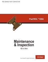
Verticon100 BGA<br />
<strong>Maintenance</strong><br />
& <strong>Inspection</strong><br />
Guide<br />
Verticon100 BGA Series<br />
PRODUCTION TEST CONTACTORS<br />
Your Contact For Higher Performance<br />
www.johnstech.com<br />
©2010 <strong>Johnstech</strong> International Corporation<br />
All rights reserved.<br />
1
Verticon100 BGA<br />
About <strong>Johnstech</strong><br />
Since 1992, <strong>Johnstech</strong> International Corporation,<br />
headquartered in Minneapolis, MN, has been a<br />
leading provider of interconnect solutions for<br />
semiconductor manufacturers who want higher<br />
first-pass yields and lower overall cost of test.<br />
<strong>Johnstech</strong>’s high performance Test Contactors are<br />
available in Ball, Pad, Leaded and Edge packages<br />
and are based on patented technology that<br />
provides superior electrical and mechanical performance.<br />
<strong>Johnstech</strong> also partners with Handler,<br />
Tester and Load Board manufacturers to ensure<br />
appropriate interfaces. With offices in the United<br />
States and Singapore; Field Service offices in<br />
California, Singapore; and representation in the<br />
U.S., China, Israel, Japan, Korea, Southeast Asia<br />
(Malaysia, Philippines, Singapore, Thailand),<br />
Taiwan, India, and Europe. <strong>Johnstech</strong> is proud to<br />
provide worldwide service and support.<br />
(Please refer to the back cover for addresses and<br />
phone numbers or go to our website at www.<br />
johnstech.com.)<br />
www.johnstech.com<br />
©2010 <strong>Johnstech</strong> International Corporation<br />
All rights reserved.<br />
2
Table of Contents<br />
Verticon100 BGA<br />
Standard Product Information . . . . . . . . . . . . . . . . . 4<br />
Contactor Component Information . . . . . . . . . . . . 5<br />
Contactor Identification Information ...........6<br />
Contactor Verification Information. . . . . . . . . . . . . 7<br />
Recommended Tools. . . . . . . . . . . . . . . . . . . . . . . . . . 8<br />
Cleaning and <strong>Maintenance</strong> Frequency . . . . . . . . . 9<br />
Pre-<strong>Maintenance</strong> Troubleshooting. . . . . . . . .10-11<br />
Load Board & Contactor <strong>Inspection</strong> . . . . . . . . . . .12<br />
Load Board <strong>Inspection</strong> . . . . . . . . . . . . . . . . . . . . . . . . . . . . . . . 12<br />
Contactor <strong>Inspection</strong>. . . . . . . . . . . . . . . . . . . . . . . . . . . . . . . . . 12<br />
Housing, Cartridge & Contact <strong>Inspection</strong> ......13<br />
Housing <strong>Inspection</strong> . . . . . . . . . . . . . . . . . . . . . . . . . . . . . . . . . . 13<br />
Cartridge <strong>Inspection</strong> . . . . . . . . . . . . . . . . . . . . . . . . . . . . . . . . . 13<br />
Contact <strong>Inspection</strong> ................................... 13<br />
Oxide Buildup . . . . . . . . . . . . . . . . . . . . . . . . . . . . . . . . . . . . . . . 13<br />
Contactor Removal & Installation . . . . . . . . . . . . .14<br />
Cartridge Removal . . . . . . . . . . . . . . . . . . . . . . . . . . .15<br />
Cartridge Install ...........................16-17<br />
Contactor Cleaning . . . . . . . . . . . . . . . . . . . . . . . . . .18<br />
For questions about anything contained in<br />
this <strong>Maintenance</strong> & <strong>Inspection</strong> Guide,<br />
contact your local <strong>Johnstech</strong> representative.<br />
If you are experiencing a technical problem<br />
or issue, fill out the online Tech Help Form at:<br />
www.johnstech.com/support<br />
(All forms will be responded to within two business days.)<br />
OR contact the nearest Field Service Office.<br />
(Turn to the back cover for addresses/phone numbers.)<br />
www.johnstech.com<br />
©2010 <strong>Johnstech</strong> International Corporation<br />
All rights reserved.<br />
3
Verticon100 BGA<br />
Standard Product Information<br />
Electrical Specifications<br />
(Measured using configuration for SAC 305 packages)<br />
Electrical Length:. . . . . . . . . . . . . . . . . . . . . . . . . . . . . . . . . . . . . . . . . . . . . . 0.95 mm<br />
Inductance: ................................................Self: 0.32 nH<br />
. . . . . . . . . . . . . . . . . . . . . . . . . . . . . . . . . . . . . . . . . . . . . . Mutual: 0.068 nH<br />
Capacitance: . . . . . . . . . . . . . . . . . . . . . . . . . . . . . . . . . . . . . . . ...Ground: 0.059 pF<br />
. . . . . . . . . . . . . . . . . . . . . . . . . . . . . . . . . . . . . . . . . . . .. Mutual: 0.012 pF<br />
S21 Insertion Loss (G-S-G): . . . . . . . . . . . . . . . . . . . . . . . . . . . . . -1 dB @ 33.7 GHz<br />
S11 Return Loss (G-S-G): . . . . . . . . . . . . . . . . . . . . . . . . . . . . . -20 dB @ 25.1 GHz<br />
S41 Crosstalk (G-S-S-G): . . . . . . . . . . . . . . . . . . . . . . . . . . . . . . . -20 dB @ 33.5 GHz<br />
Average Contact DC Resistance:. . . . . . . . . . .....2,000,000<br />
Mechanical Compliance: . . . . . . . . . . . . . . . . . . . . . . . . . . . . . . .........0.37 mm<br />
Electrical Compliance (operating range).
Contactor Components<br />
Verticon100 BGA<br />
Methodology<br />
Contactor Components<br />
Device<br />
Under Test<br />
Upper<br />
Contact<br />
Elastomeric<br />
Laminate<br />
Lower<br />
Contact<br />
Load<br />
Board<br />
Methodology<br />
The <strong>Johnstech</strong> Verticon<br />
Contactor is designed to be<br />
fully compressed by pushing<br />
the device under test to a<br />
force (nominally 35 grams per<br />
ball). If the handler cannot<br />
push to a force, then the<br />
Contactor should be compressed<br />
to 0.95 mm. As the<br />
device is pushed against the<br />
Contactor, the device ball<br />
is wiped to break through<br />
debris that might be present<br />
on the ball. This results in<br />
better electrical measurements<br />
and longer intervals<br />
before cleaning is required.<br />
Electrical signals are carried<br />
by the Contactor contacts<br />
from the device under test to<br />
the load board.<br />
The <strong>Johnstech</strong> Verticon<br />
Contactor has three field<br />
replaceable components that<br />
comprise the Contactor assembly:<br />
Fully-Assembled Contactor<br />
(top view)<br />
Housing with no<br />
Cartridge (bottom view)<br />
•<br />
•<br />
•<br />
Housing<br />
Alignment Plate<br />
Cartridge (contacts +<br />
elastomeric laminate)<br />
A manual actuator is available<br />
for short run testing and<br />
characterization.<br />
Housing and Cartridge<br />
(bottom view)<br />
Z Axis Manual Actuator (ZMA)<br />
Bolt-down style for ball counts<br />
81-2704<br />
DL-VCMA<br />
Clamp-on style for<br />
ball counts of 0-100<br />
www.johnstech.com<br />
©2010 <strong>Johnstech</strong> International Corporation<br />
All rights reserved.<br />
5
Verticon100 BGA<br />
Identification<br />
Each <strong>Johnstech</strong> Contactor<br />
will have as much information<br />
as space allows. The<br />
identification system is designed<br />
to provide you with<br />
the technical information<br />
you need to identify the<br />
Contactor and its Design<br />
Data Sheet (example shown<br />
on the facing page).<br />
Contactor Identification<br />
Sample Contactor, Load Board Side Up<br />
9. Device Body 1. Manufacturer 6. Assembly 7. Device 8. Device<br />
Size (mm) Type Count Type<br />
5. Design Number<br />
10. Pitch (mm)<br />
3. Manufacturing<br />
Date Code<br />
Here is how to read the<br />
different data fields on the<br />
Contactors:<br />
1. JTI identifies <strong>Johnstech</strong><br />
International as<br />
the manufacturer<br />
2. Serial Number<br />
3. Manufacturing Date<br />
Code (see tables at right)<br />
4. Perimeter Contact Width<br />
(in inches)<br />
5. Design Number<br />
For Custom Orders:<br />
1234-YYZZ<br />
YY = Contactor<br />
Technology Code<br />
02 = ROL200<br />
K2 = Kelvin<br />
ZZ = Configuration<br />
(or design iteration)<br />
Number<br />
For SelecTest® Order:<br />
6XXX-8XXXXX<br />
6XXX = Design Number<br />
8XXXXX = Configuration<br />
Number<br />
6. Assembly Type<br />
TS: Test Socket<br />
MA: Manual Actuator<br />
7. Device Perimeter Pad<br />
Count<br />
8. Device Type<br />
9. Device Body Size (mm)<br />
10. Device Ball Pitch (mm)<br />
11. Part Number (will appear<br />
only if Contactor is<br />
a SelecTest® order)<br />
www.johnstech.com<br />
©2010 <strong>Johnstech</strong> International Corporation<br />
All rights reserved.<br />
6<br />
Date Code Reference<br />
Week<br />
Week<br />
Letter Number Letter Number<br />
A 1 AA 27<br />
B 2 AB 28<br />
C 3 AC 29<br />
D 4 AD 30<br />
E 5 AE 31<br />
F 6 AF 32<br />
G 7 AG 33<br />
H 8 AH 34<br />
I 9 AI 35<br />
J 10 AJ 36<br />
K 11 AK 37<br />
L 12 AL 38<br />
M 13 AM 39<br />
N 14 AN 40<br />
O 15 AO 41<br />
P 16 AP 42<br />
Q 17 AQ 43<br />
R 18 AR 44<br />
S 19 AS 45<br />
T 20 AT 46<br />
U 21 AU 47<br />
V 22 AV 48<br />
W 23 AW 49<br />
X 24 AX 50<br />
Y 25 AY 51<br />
Z 26 AZ 52<br />
Date Code Examples:<br />
SN123456BK B = Week 2 K = 2001<br />
SN654321AAN AA = Week 27 N = 2004<br />
11. Part Number<br />
2. Serial Number<br />
4. Perimeter<br />
Contact Width<br />
Letter<br />
Year<br />
A 1991<br />
B 1992<br />
C 1993<br />
D 1994<br />
E 1995<br />
F 1996<br />
G 1997<br />
H 1998<br />
I 1999<br />
J 2000<br />
K 2001<br />
L 2002<br />
M 2003<br />
N 2004<br />
O 2005<br />
P 2006<br />
Q 2007<br />
R 2008<br />
S 2009<br />
T 2010<br />
U 2011<br />
V 2012
Contactor Configuration Verification<br />
Verticon100 BGA<br />
Verify the Alignment Plate<br />
Part #: xxxxxx<br />
Check the part number (in red box) against Design Data<br />
Sheet (below) to ensure it is correct.<br />
Example of Design Data Sheet<br />
Design Data Sheet<br />
The Design Data Sheet<br />
contains Contactor<br />
specifications on load board<br />
layout, contact compressed<br />
height, alignment plate<br />
opening size, and other<br />
information necessary for<br />
setup and troubleshooting.<br />
Refer to it to verify you are<br />
using the correct:<br />
· Alignment plate<br />
· Load board layout<br />
Alignment Plate<br />
Verification<br />
Refer to the Design Data<br />
Sheet to ensure the proper<br />
alignment plate is being<br />
used. Different package<br />
vendors and handlers<br />
require different alignment<br />
plates. The Design Data<br />
Sheet will specify the<br />
correct alignment plate for<br />
specific applications, as well<br />
as any special engraving to<br />
assist with identification.<br />
The Design Data Sheet may be a multiple-page document.<br />
Make sure the Part Numbers (in the red boxes) match up.<br />
www.johnstech.com<br />
©2010 <strong>Johnstech</strong> International Corporation<br />
All rights reserved.<br />
7
Verticon100 BGA<br />
Recommended Tools<br />
Screwdriver with Allen-Head Bits— for fastening the<br />
Contactor to the load board<br />
30X+ Eye Loupe— for magnified inspection of Contactor and<br />
contacts<br />
Elastomer Tool— for use in other <strong>Johnstech</strong> Contactors as<br />
well as prying alignment plate from Contactor. Used in installing<br />
cartridge in BGA product.<br />
Recommended tools<br />
(in order at right)<br />
Fine-Tip Non-Metallic Tweezers— for handling contacts,<br />
elastomers, and cartridges.<br />
Craft Knife<br />
Micro Scissors<br />
Probe Tool<br />
Fiberglass Brush and Replacement Tips— recommended<br />
for cleaning the contacts (If fiberglass brushes are not allowed<br />
on the test floor, although not optimum, nylon brushes can be<br />
substituted.)<br />
EXTRAS:<br />
Finger Cots— recommended to prevent contaminating Contactor<br />
components with skin oils.<br />
Protective Eyewear— recommended to protect technicians<br />
from test floor/Contactor components, compressed air and<br />
other chemicals.<br />
<strong>Johnstech</strong> <strong>Maintenance</strong> & <strong>Inspection</strong> Kit<br />
CAUTION: Avoid touching<br />
the device- and load<br />
board-interface surfaces<br />
of the contacts with<br />
metal tools. Scratches<br />
on these areas may<br />
degrade performance.<br />
<strong>Johnstech</strong> <strong>Maintenance</strong> & <strong>Inspection</strong> Kit contains many of the<br />
tools needed for maintenance and inspection and are designed<br />
especially for <strong>Johnstech</strong> high performance Contactors. Contact<br />
your <strong>Johnstech</strong> representative for more information.<br />
www.johnstech.com<br />
©2010 <strong>Johnstech</strong> International Corporation<br />
All rights reserved.<br />
8<br />
<strong>Maintenance</strong> Kit Part Numbers —<br />
with torque screwdriver: 706449<br />
without torque screwdriver: 706448
Cleaning & <strong>Maintenance</strong> Frequency<br />
Verticon100 BGA<br />
Determining Frequency<br />
Due to a wide range of variables (like those listed below),<br />
each test floor must determine their optimal cleaning and<br />
maintenance intervals through effective use of statistical<br />
process control. By carefully monitoring and recording<br />
yield rates and following good test floor troubleshooting<br />
procedures, you will be able to clearly differentiate between<br />
interface vs. maintenance problems and an effective<br />
maintenance cleaning cycle can be established to match<br />
the needs of each test floor. Contact your <strong>Johnstech</strong><br />
representative or field service staff for further information or<br />
help.<br />
Handler Design and Setup<br />
Handlers have a variety of test plane configurations,<br />
device transportation methods, plunge mechanisms, and<br />
accessories. Each handler has its own unique attributes.<br />
Handler set-ups that are not optimized can increase<br />
the required maintenance frequency by contributing to<br />
premature Contactor wear and debris build-up on the<br />
contacts. By working with <strong>Johnstech</strong> and your handler<br />
supplier, you can optimize handler performance to minimize<br />
downtime.<br />
Correct Contact Compressed Height<br />
<strong>Johnstech</strong> Verticon 100 BGA Contactors are designed to be<br />
compressed to a nominal height of 0.95 mm above the top<br />
plane of the load board. To accommodate variation in package<br />
thickness, the handler should be programmed to push to a<br />
force of 35 grams per ball (at ambient temperature) or use a<br />
compliant chuck.<br />
Package and Device Plating Variations<br />
Variations in packages can affect your maintenance schedule.<br />
Different package vendors, or even different device lots, may<br />
have varying amounts of mold flash that can increase wear<br />
on the Contactor and alter device placement. Also, the device<br />
plating can vary the rate of debris build-up, and therefore vary<br />
the maintenance interval.<br />
Contaminants<br />
Accumulation of contaminants on the contactor and/or load<br />
board (such as debris and mold flash) may contribute to<br />
continuity and/or parametric failures during the test process.<br />
General Test Floor <strong>Maintenance</strong> Activities<br />
The frequency of handler maintenance procedures also affects<br />
Contactor cleaning. For example, how often the handler and<br />
handler test areas are blown free and/or vacuumed of debris<br />
impacts the effectiveness of the Contactor. Contactors<br />
exposed to increased levels of foreign debris are likely to<br />
require more frequent maintenance and cleaning.<br />
www.johnstech.com<br />
©2010 <strong>Johnstech</strong> International Corporation<br />
All rights reserved.<br />
9
Verticon100 BGA<br />
Pre-<strong>Maintenance</strong> Troubleshooting<br />
If experiencing<br />
problems in automated<br />
test, first answer these<br />
2 questions:<br />
1) Does the test<br />
Contactor work when<br />
manually testing with<br />
the manual actuator?<br />
2) Do the witness<br />
marks from the manual<br />
actuator test look the<br />
same as those from the<br />
automated test?<br />
If the answer to both<br />
questions is YES, then<br />
your test problem is<br />
probably caused by<br />
some variable other<br />
than your <strong>Johnstech</strong><br />
Contactor.<br />
If the answer to either<br />
question is NO, then<br />
read through the<br />
checklists on these<br />
2 pages, under the<br />
problem (in red) that<br />
you are experiencing.<br />
If this application has<br />
run well previously<br />
but is now failing,<br />
the troubleshooting<br />
must determine what<br />
has changed. If this<br />
is a new application,<br />
troubleshooting must<br />
examine the original<br />
design.<br />
This pre-maintenance troubleshooting section is<br />
designed to help you determine which part of your<br />
<strong>Johnstech</strong> Contactor may need to be inspected and/<br />
or serviced to address a particular test problem. This<br />
section doesn’t cover test floor, handler, device, or any<br />
other variables that might need to be contributing to<br />
your test problem. If you still experience problems<br />
after following the maintenance instructions herein,<br />
contact your local <strong>Johnstech</strong> representative or fillout<br />
our online Contact Technical Support form at:<br />
www.johnstech.com/support<br />
Experiencing Yield Fall-Off?<br />
There are many reasons you may be experiencing yield falloff<br />
but it can frequently be attributed to either parametric or<br />
continuity failures.<br />
Parametric Failures are typically due to increased contact<br />
resistance which can be caused by:<br />
· Dirty Contacts (Page 13, Figure 5)<br />
Clean contacts per instructions on Page 18.<br />
· Worn or Damaged Cartridge (Page 13)<br />
Reinstall new cartridge per instructions on Page 16.<br />
· Excessive Load Board Wear (Page 12, Figure 1)<br />
Inspect the load board per instructions on Page 12.<br />
· Contamination on the Load Board (Page 12, Figure 1)<br />
Inspect the load board per instructions on Page 12.<br />
· Worn or Damaged Alignment Plate (Page 12, Figures 2 & 3)<br />
Inspect the alignment plate under Contactor inspection<br />
instructions on Page 12.<br />
· Device Ball-to-Contact Misalignment (Page 13, Figure 4)<br />
Inspect the Contactor per instructions on Page 13.<br />
· Worn or Damaged Leadbacker/Nest<br />
Inspect the leadbacker and nest.<br />
Continuity Failures are typically due to open/short failures<br />
which can be caused by:<br />
· Excessive Loose Debris<br />
Inspect Contactor per instructions on Page 12.<br />
· Contamination of the Load Board (Page 12, Figure 1)<br />
Inspect the Load Board per instructions on Page 12.<br />
· Worn or Damaged Alignment Plate (Page 12, Figures 2 & 3)<br />
Inspect the alignment plate opening under the Contactor.<br />
<strong>Inspection</strong> instructions on Page 12.<br />
· Worn or Damaged Contacts (Page 16, Figure 5)<br />
Replace cartridge per instructions on Page 16.<br />
· Worn or Damaged Leadbacker/Nest<br />
Inspect the leadbacker and nest.<br />
www.johnstech.com<br />
©2010 <strong>Johnstech</strong> International Corporation<br />
All rights reserved.<br />
10
Pre-<strong>Maintenance</strong> Troubleshooting<br />
Verticon100 BGA<br />
Experiencing Device Damage or Jamming?<br />
There can be many reasons why you may experience device<br />
damage or jamming. For example, incorrectly designed<br />
or incompatible, worn or damaged handler/Contactor<br />
components may cause ball damage or device jamming.<br />
Device Ball Damage or Improper Wipe can happen when<br />
contacts are out of alignment or when the handler is pushing<br />
too high a force. Witness marks should be near the center of<br />
the device balls. If not, the problems can occur due to:<br />
· Worn or Damaged Alignment Plate Opening (Page 12, Figures<br />
2 & 3) Inspect the alignment plate under Contactor inspection<br />
instructions on Page 12.<br />
· Worn or Damaged Leadbacker/Nest<br />
Inspect the leadbacker and nest.<br />
· Changes in Package Singulation<br />
Verify that the alignment plate and leadbacker are correct for the<br />
device by comparing device dimensions to the Design Data Sheet.<br />
· Improper Overtravel Control<br />
Verify that leadbacker/nest has proper overtravel control. Refer<br />
to the Contactor specifications on your Design Data Sheet for<br />
compressed, uncompressed, and overtravel stop dimensions.<br />
Device Ball Damage or Improper Wipe can also occur when<br />
devices experience over deflection, whereby large witness<br />
marks appear. This is can be attributed to:<br />
· Worn or Damaged Leadbacker/Nest<br />
Inspect the leadbacker and nest.<br />
· Improper Overtravel Control<br />
Verify that leadbacker/nest has proper overtravel control. Refer<br />
to the Contactor specifications on your Design Data Sheet for<br />
compressed, uncompressed and overtravel stop dimensions.<br />
Device Jams can occur due to:<br />
· Worn or Damaged Alignment Plate Opening (Page 12, Figures<br />
2 & 3) Inspect the alignment plate opening under Contactor<br />
inspection instructions on Page 12.<br />
· Device Ball-to-Contact Misalignment (Page 13, Figure 4)<br />
Inspect the Contactor per instructions on Page 13.<br />
· Worn or Damaged Leadbacker/Nest<br />
Inspect the leadbacker and nest.<br />
· Changes in Package Singulation<br />
Verify that the alignment plate and leadbacker are correct for the<br />
device by comparing device dimensions to the Design Data Sheet.<br />
· Improper Overtravel Control<br />
Verify that the leaderbacker/nest has proper overtravel or safety<br />
stop control. Refer to the Contactor specifications on your Design<br />
Data Sheet for compressed, uncompressed and overtravel or<br />
safety stop measurement.<br />
www.johnstech.com<br />
©2010 <strong>Johnstech</strong> International Corporation<br />
All rights reserved.<br />
11
Verticon100 BGA<br />
Load Board & Contactor <strong>Inspection</strong><br />
Load Board <strong>Inspection</strong><br />
<strong>Johnstech</strong> recommends performing a thorough inspection of<br />
the load board before initial installation of the Contactor, as<br />
well as when performing routine maintenance. First, however,<br />
verify your load board against the load board drawing that<br />
was sent to you either with your quote or your order.<br />
Figure 1:<br />
Example of a load board pad<br />
pattern<br />
Next, check the contact load board pad pattern for signs<br />
of wear on the gold. See Figure 1. If nickel is showing,<br />
make sure that it is not excessive. It is acceptable to utilize<br />
the nickel surface during testing, however, in some RF<br />
applications, signal degradation will occur. Load boards with<br />
wear that extends deeper than the nickel surface (through to<br />
the copper) can cause damage to the contacts and should be<br />
replaced or repaired.<br />
NOTE: Excessive load board wear is typically caused by<br />
excessive force on the Contactor housing.<br />
Contactor <strong>Inspection</strong><br />
CAUTION: Use special care during the inspection process.<br />
Excessive force can damage the cartridge.<br />
Figure 2:<br />
Example of worn (vs. not worn<br />
on right) alignment plate wall;<br />
needs to be replaced<br />
Figure 3:<br />
Example of backlit alignment<br />
plate wear test<br />
Before removing the Contactor from the load board, use a<br />
minimum of 30X+ magnification to inspect it for:<br />
· Damaged, missing, or excessively worn contacts<br />
· Debris and mold flash trapped in or around contacts<br />
· Cracks or chipping in the housing or alignment plate<br />
· Worn alignment plate (ALPL) walls — See Figure 2.<br />
NOTE: Remove Contactor from load board (per instructions on<br />
Pages 14) to test for ALPL wear. On a backlit surface, place<br />
device into the ALPL opening and then push it to one corner<br />
(See Figure 3). Use a feeler gauge stock of 0.10mm to check<br />
the gaps on the opposite sides. If feeler gauge stock slips in<br />
and out of gap easily, the ALPL is worn more than spec and<br />
should be replaced.<br />
· Worn handler alignment pin holes (contact your <strong>Johnstech</strong><br />
representative for bushings to reduce Contactor wear.)<br />
If any of the above conditions are observed, Contactor<br />
maintenance and possibly contact/elastomer or ALPL<br />
replacement is required.<br />
www.johnstech.com<br />
©2010 <strong>Johnstech</strong> International Corporation<br />
All rights reserved.<br />
12
Housing, Cartridge & Contact <strong>Inspection</strong><br />
Verticon100 BGA<br />
In order to inspect the housing, cartridge, and<br />
contacts, the Contactor must be removed from the<br />
load board and disassembled. Refer to instructions<br />
on Page 14.<br />
Housing <strong>Inspection</strong><br />
Take the dismounted/disassembled Contactor and using a<br />
minimum of 30X+ magnification, inspect the housing and<br />
check the alignment plate walls for wear. If wear is observed,<br />
replace the alignment plate.<br />
Verticon100 BGA housings have a recommended lifespan of 2<br />
million insertions.<br />
Cartridge <strong>Inspection</strong><br />
Using 30X+ magnification, inspect the cartridge for signs of<br />
cuts, tears, and stretched sections.<br />
Figure 4:<br />
Acceptable contact wipe on<br />
ball (on SAC)<br />
Upon inspection, if you see worn areas replace the cartridge<br />
to regain optimum performance. See Page 16 for replacement<br />
procedure.<br />
Contact <strong>Inspection</strong><br />
Using 30X+ magnification, inspect the contacts for signs of:<br />
· Worn Contacts<br />
· Scratches or Markings<br />
· Debris Buildup (See Figure 5)<br />
· Compressed/Distorted Shape<br />
The self-cleaning wipe-action of the Verticon TM 100 BGA is<br />
designed to greatly reduce the amount of debris build up on<br />
contacts. However, some debris accumulation can occur. To<br />
clean the contacts, follow the cleaning procedure on Pages<br />
18-19. If any other conditions are observed, please contact<br />
a <strong>Johnstech</strong> service representative or order a replacement<br />
cartridge.<br />
Figure 5:<br />
Example of debris buildup<br />
on contact tip (photo is from<br />
a test on SAC)<br />
NOTE: If contacts have significant/excessive debris build-up,<br />
check all components in the test cell to ensure that device<br />
alignment and plunge depth are correct.<br />
www.johnstech.com<br />
©2010 <strong>Johnstech</strong> International Corporation<br />
All rights reserved.<br />
13
Verticon100 BGA<br />
Contactor Removal and Installation<br />
Contactor Removal & Installation Instructions<br />
It is recommended that you remove your Verticon100<br />
BGA Contactor from the load board before<br />
performing any component inspection, cleaning and/<br />
or maintenance.<br />
Figure 6:<br />
Screw tightening pattern<br />
Step 1— Remove Contactor<br />
Start removal of the Contactor from the load board by<br />
removing the fasteners. Carefully lift the Contactor away from<br />
the load board to ensure that the contacts are not sliding<br />
against the load board pads. Once the Contactor is removed,<br />
inspect it for any loose or missing contacts. Mount the Contactor<br />
to the clear mounting plate, which the Contactor was mounted<br />
to when originally shipped, for storage.<br />
Step 2— Perform <strong>Maintenance</strong> & Cleaning<br />
Perform the maintenance and cleaning per the instructions<br />
contained on the following pages.<br />
Step 3— Clean Load Board<br />
Before remounting the Contactor to the load board, ensure<br />
that no debris is present in the interface areas. If necessary,<br />
use compressed air and/or isopropyl alcohol with a clean<br />
lint-free cloth to carefully wipe the surface of the load board.<br />
Recommended<br />
Torque Values<br />
in.-lb. Nm<br />
0-80 1.0 0.11<br />
2-56 2.0 0.23<br />
4-40 5.0 0.56<br />
M1.4 x 0.3 0.4 0.04<br />
M1.6 x 0.35 0.6 0.06<br />
M2 x 0.40 1.3 0.15<br />
M2.5 x 0.45 2.5 0.28<br />
M3 x 0.5 4.5 0.51<br />
M4 x 0.7 8.0 0.90<br />
Figure 7:<br />
Recommended Torque<br />
Values<br />
NOTE: NEVER use acetone or other solvents.<br />
Step 4— Install Contactor<br />
Inspect the load board pads’ size and shape. Orient the Contactor<br />
so that the contact feet have maximum footing area on the<br />
load board pads. Before fastening the Contactor to the load<br />
board, check for interference between the Contactor and the<br />
load board components and traces. Place the Contactor on<br />
the load board and check for gaps. Caution: Do not fasten the<br />
Contactor onto the load board if it cannot sit flat on the load<br />
board. Either remove obstacles and /or consult <strong>Johnstech</strong> if<br />
the Contactor does not sit flat on the load board. Attach the<br />
Contactor to the load board by fitting the fasteners through the<br />
Contactor and engaging several threads. If possible, inspect<br />
the contact tips under a microscope or with an eye loupe for<br />
symmetrical alignment of the contacts across the array. Evenly<br />
tighten the fasteners in a crisscross pattern. See Figure 6. To<br />
avoid damage to the Contactor, use the recommended torque<br />
values shown in Figure 7.<br />
www.johnstech.com<br />
©2010 <strong>Johnstech</strong> International Corporation<br />
All rights reserved.<br />
14<br />
Step 5— Verify Test Set-up<br />
Verify the device-to-Contactor alignment and handler plunge<br />
depth, as well as the X-Y presentation.
Cartridge Removal Instructions<br />
Verticon100 BGA<br />
NOTE: Never try to replace the individual contacts. The cartridge<br />
is not designed to have individual contacts taken out<br />
or replaced. However, you can clean the tips of the contacts<br />
if you experience low yields or other production issues. See<br />
Page 18 for the cleaning procedure.<br />
We recommend you use the following procedures to remove<br />
the cartridge and to install a new one.<br />
Removing Cartridge From Contactor (Housing/<br />
Alignment Plate Assembly)<br />
Step 1— Positioning the Housing<br />
Remove the housing/alignment plate from the load board.<br />
See Page 14 for instructions. Then remove the alignment<br />
plate from the housing. To do so, use a rigid, flat tool (e.g.<br />
the craft knife or the blue elastomer tool found in the <strong>Johnstech</strong><br />
<strong>Maintenance</strong> & <strong>Inspection</strong> Kit) to gently pry the two<br />
pieces apart, working in an even and incremental manner<br />
around the housing. See Figure 8. Position the housing of<br />
the Contactor with the top (device side) up.<br />
Step 2— Push Cartridge Out<br />
Firmly grasp the housing of the Contactor. With the flat end<br />
of the blue elastomer tool (provided in the <strong>Maintenance</strong> and<br />
<strong>Inspection</strong> Kit) begin to push out the cartridge from the top<br />
(device side) of housing. See Figure 9.<br />
Continue to gently push the cartridge along the perimeter<br />
of the housing opening until the cartridge is removed. See<br />
Figure 10.<br />
Figure 8:<br />
Remove the alignment<br />
plate from housing.<br />
Figure 9:<br />
Push the cartridge out of<br />
housing.<br />
Follow the instructions on the next page for installing a new<br />
cartridge.<br />
Figure 10:<br />
Cartridge separates from<br />
the housing.<br />
www.johnstech.com<br />
©2010 <strong>Johnstech</strong> International Corporation<br />
All rights reserved.<br />
15
Verticon100 BGA<br />
Cartridge Installation Instructions<br />
NOTE: Never try to replace the individual Verticon100 BGA contacts.<br />
The cartridge is not designed to have individual contacts<br />
taken out or replaced.<br />
Installing Cartridge Replacement into the<br />
Housing<br />
Figure 11:<br />
Bottom (load board side) of<br />
housing.<br />
Figure 12:<br />
Bottom (load board side) of<br />
contacts.<br />
Step 1— Before Installing<br />
When you are ready to install the cartridge, find the empty<br />
housing and position it with the bottom side (load board<br />
side) up. See Figure 11. Handle the new cartridge on the<br />
outside of the contact area with tweezers to avoid contamination.<br />
Use a microscope to identity the bottom (load board<br />
side) of the new cartridge. See Figure 12. Position the new<br />
cartridge , bottom side up over the housing. Align the square<br />
corner of the cartidge with the recessed corner of the housing.<br />
See Figure 13.<br />
Step 2— Insert Cartridge Under Retention Lip<br />
Center the cartridge over the bottom (load board side),<br />
aligning the rows of holes in the cartridge with the alignment<br />
marks on the perimeter of the housing. See Figure 14. Gently<br />
push around the perimeter of the cartridge with the flat<br />
end of the blue elastomer tool to tuck the edge of the cartridge<br />
under the retention lip. See Figure 15. Work around all<br />
four sides of the cartridge until the cartridge surface is flush<br />
with the housing. The cartridge should be smooth across.<br />
Bottom Side of Contactor<br />
Alignment Marks<br />
Figure 13:<br />
Recessed corner of Housing<br />
Square Corner of cartridge<br />
Retention Lip<br />
Alignment Post<br />
Inner Wall<br />
Top side of Contactor/housing<br />
Figure 14:<br />
Tuck in the edge of the<br />
cartridge.<br />
Helpful Hints<br />
• Line up posts under microscope<br />
• Push evenly around perimeter<br />
www.johnstech.com<br />
©2010 <strong>Johnstech</strong> International Corporation<br />
All rights reserved.<br />
16
Cartridge Installation Instructions<br />
Verticon100 BGA<br />
Step 3— Confirm that the Cartridge is Properly<br />
Installed<br />
Turn the housing with the cartridge installed over to the top<br />
side (device side) of the housing. Tilt the housing vertically<br />
to view the intersection of the housing opening and the cartridge.<br />
If the cartridge is not properly installed, small posts<br />
in the housing will be visible. See Figure 16. If the cartridge<br />
is properly installed, the posts will not be visible. If the<br />
cartridge is not properly installed, remove the cartridge, following<br />
the instructions on Page 15. Repeat the installation<br />
following the instructions on Pages 16-17. When you have<br />
confirmed that the cartridge is properly installed, reassemble<br />
the alignment plate on the housing.<br />
Figure 15:<br />
Align holes in cartridge<br />
with alignment marks<br />
(shown in blue).<br />
Figure 16:<br />
If the cartridge is not<br />
properly installed, small<br />
posts will be visible.<br />
www.johnstech.com<br />
©2010 <strong>Johnstech</strong> International Corporation<br />
All rights reserved.<br />
17
Verticon100 BGA<br />
Contactor Cleaning<br />
If debris buildup is observed upon inspection of<br />
the Contactor or you experience a drop in yields or<br />
an increase in contact resistance, follow the Light<br />
Cleaning Procedure on this page.<br />
NOTE: Never use cleaning solvents to clean the contacts. Solvents<br />
can be absorbed by the elastomer which will result in poor<br />
performance.<br />
Figure 17:<br />
Clean contact tips with<br />
an ultra fine tip fiberglass<br />
Light Cleaning Procedure<br />
Step 1— Remove the Contactor from load board<br />
Refer to instructions on Page 14 Step 1.<br />
Step 2— Remove Alignment Plate<br />
Refer to instructions on Page 15, Step 1.<br />
Figure 18:<br />
The correct direction to clean<br />
contacts<br />
Step 3— Brush the Device Side of Contactor<br />
A. Mount the Contactor to the clear mounting plate, which<br />
the Contactor was mounted to when originally shipped.<br />
This will support the cartridge as you clean.<br />
B. Use an ultra fine tip fiberglass brush to clean the<br />
contact tips as shown in Figure 17.<br />
C. Brush the contacts gently as show in Figure 18,<br />
brushing the top contact tips back and forth along<br />
the diagonal contact rows until debris is removed.<br />
Figure 18 shows correct direction to clean. Figure<br />
19 shows the incorrect cleaning direction.<br />
NOTE: The correct cleaning direction is along the diagonal rows,<br />
not across the rows. Brush only the contacts. Avoid the<br />
surface of the cartridge to minimize scratches.<br />
NOTE: Use an ultra fine tip fiberglass brush like the one below to<br />
clean the Verticon 100 BGA Contactor and contacts. If fiberglass<br />
is not permitted in your facility, a nylon brush can be used as a<br />
substitute.<br />
Ultra Fine Tip Fiberglass Brush - <strong>Johnstech</strong> Part No 160592-1<br />
Ultra Fine Tip Fiberglass Refills - <strong>Johnstech</strong> Part No 160593-1<br />
Figure 19:<br />
The incorrect direction to<br />
clean contacts<br />
NOTE: Never try to replace the individual BGA contacts. The BGA<br />
cartridge is not designed to have individual contacts taken out or<br />
replaced.<br />
www.johnstech.com<br />
©2010 <strong>Johnstech</strong> International Corporation<br />
All rights reserved.<br />
18
Contactor Cleaning<br />
Verticon100 BGA<br />
Step 4— Brush the Load Board Side of the Contactor<br />
A. After the top contacts have been cleaned, turn over<br />
the Contactor so that the load board side is up.<br />
B. Using compressed air or canned air, blow loose debris<br />
from the bottom contacts.<br />
C. If some debris remains, gently clean the contacts<br />
using the ultra fine tip fiberglass brush. Clean the<br />
load board side contacts as show in Figure 19 and<br />
Figure 20.<br />
Step 5— Clear Debris<br />
Remove any loose debris from the Contactor using one or<br />
both of these methods:<br />
· Dry, clean compressed air (20psi or less) See Figure 21<br />
· A small vacuum<br />
· Canned air See Figure 22<br />
Once the Contactor is thoroughly clear of debris, it is ready<br />
to be reassembled and reinstalled.<br />
Step 6— Clean the Handler<br />
Clean the handler per manufacturer’s recommendation.<br />
Step 7— Clean the Load Board<br />
Before remounting the Contactor to the load board, ensure<br />
that no debris is present in the interface areas. If necessary,<br />
use compressed air and/or ispropyal alcohol with a clean<br />
lint-free cloth to carefully wipe the load board clean.<br />
Figure 19:<br />
Cleaning the load board side<br />
of the contacts<br />
Figure 20:<br />
Only occasional light<br />
cleaning should be<br />
required for the bottom<br />
NOTE: Never use acetone or other solvents.<br />
Step 8— Reinstall the Contactor<br />
If no loose debris remains on the Contactor, remount it to<br />
the load board per the instructions on Page 14.<br />
NOTE: If these cleaning procedures do not help your overall<br />
performance, remove the cartridge per instructions on page<br />
15 and install a new cartridge.<br />
Figure 21:<br />
Compressed air cleaning<br />
If the recommended cleaning tool/brush is not allowed<br />
in your facility, a nylon brush can be used as a substitute.<br />
Contact your <strong>Johnstech</strong> Representative if you have additional<br />
questions.<br />
Figure 22:<br />
Compressed air cleaning<br />
www.johnstech.com<br />
©2010 <strong>Johnstech</strong> International Corporation<br />
All rights reserved.<br />
19
Verticon100 BGA<br />
All statements, technical<br />
information and recommendations<br />
related to the Seller’s products<br />
are based on information believed<br />
to be reliable, but the accuracy<br />
or completeness thereof is not<br />
guaranteed. Before utilizing the<br />
product, the user shall determine<br />
the suitability of the product<br />
for its intended use. The user<br />
assumes all risks and liability<br />
whatsoever in connection with<br />
such use. Any statements or<br />
recommendations of the Seller<br />
which are not contained in the<br />
Seller’s current publications shall<br />
have no force or effect unless<br />
contained in an agreement signed<br />
by an authorized officer of the<br />
Seller. The statements contained<br />
herein are made in lieu of all<br />
warranties expressed or implied,<br />
including but not limited to the<br />
implied merchantability and<br />
fitness for a particular purpose<br />
which warranties are hereby<br />
expressly disclaimed. Seller shall<br />
not be liable to the user or any<br />
other person under any legal<br />
theory, including but not limited<br />
to negligence or strict liability,<br />
for any injury or for any direct or<br />
consequential damages sustained<br />
or incurred by reason of the use<br />
of any of Seller’s products or<br />
services that were defective.<br />
Worldwide Headquarters<br />
1210 New Brighton Boulevard<br />
Minneapolis, MN 55413-1641 USA<br />
Tel: 612.378.2020<br />
Fax: 612.378.2030<br />
E-mail: info@johnstech.com<br />
www.johnstech.com<br />
Regional/Field Service Office — California, USA<br />
2450 Scott Boulevard<br />
Santa Clara, CA 95050-2504<br />
Tel: 408.448.2020<br />
Fax: 408.448.2030<br />
www.johnstechhelp.com<br />
Regional/Field Service Office — Singapore<br />
14 Robinson Road #13-00<br />
Far East Finance Building<br />
Singapore 048545<br />
Tel: 65.6385.2389<br />
Fax: 65.6323.1839<br />
© Copyright 2010 <strong>Johnstech</strong> International<br />
Corporation Specifications subject to change.<br />
Specifications subject to change without notice.<br />
No part of this document may be reproduced<br />
in any form or by any means, electronic<br />
or mechanical, including photocopying,<br />
recording or by any information storage or<br />
retrieval system, without expressed written<br />
permission from <strong>Johnstech</strong>. <strong>Johnstech</strong> and<br />
<strong>Johnstech</strong> logo are registered trademark s<br />
in the USA and other countries. <strong>Johnstech</strong><br />
products and components are covered by<br />
patents and copyrights in the USA and other<br />
countries.<br />
For questions about anything contained in this<br />
<strong>Maintenance</strong> & <strong>Inspection</strong> Guide, contact your local<br />
<strong>Johnstech</strong> representative.<br />
If you are experiencing a technical problem or issue,<br />
fill out the online Contact Technical Support Form at:<br />
www.johnstech.com/support or contact the nearest field<br />
service office.<br />
China &<br />
EU RoHS<br />
Compliant<br />
LIT 1465-0311<br />
Printed in the USA on 100% Post-Consumer Recycled Paper made utilizing Wind Power.<br />
www.johnstech.com<br />
©2009 <strong>Johnstech</strong> International Corporation<br />
All rights reserved.<br />
20<br />
Your Contact For Higher Performance


