Pad ROL⢠200 XT - Johnstech
Pad ROL⢠200 XT - Johnstech
Pad ROL⢠200 XT - Johnstech
Create successful ePaper yourself
Turn your PDF publications into a flip-book with our unique Google optimized e-Paper software.
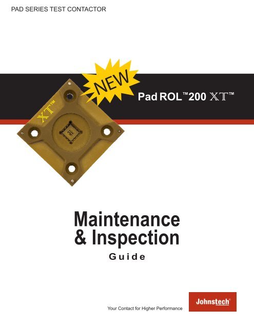
PAD SERIES TEST CONTACTOR<strong>XT</strong> NEW<strong>Pad</strong> ROL <strong>200</strong> <strong>XT</strong> Maintenance& InspectionGuideYour Contact for Higher Performance
<strong>Pad</strong> ROL <strong>200</strong> <strong>XT</strong> For questions about anythingcontained in this Maintenance &Inspection Guide, contact yourlocal <strong>Johnstech</strong> representative.If you are experiencing a technicalproblem or issue, fill out the onlineTech Help Form at:www.johnstech.com(All forms will be responded towithin two business days.)OR contact the nearest FieldService Office.(Turn to the back cover foraddresses/phone numbers.)ABOUT JOHNSTECHSince 1992, <strong>Johnstech</strong> International Corporation, headquartered in Minneapolis,MN, has been a leading provider of interconnect solutions for semiconductormanufacturers who want higher first-pass yields and lower overall cost of test.<strong>Johnstech</strong>’s high performance Test Contactors are available in <strong>Pad</strong>, Leaded,BGA, and Edge packages and are based on patented technology that providessuperior electrical and mechanical performance. <strong>Johnstech</strong> also partnerswith Handler, Tester and Load Board manufacturers to ensure appropriateinterfaces. With offices in the United States and Singapore; Field Service officesin California, Singapore, Philippines; and representation in China, Israel, Japan,Korea, Southeast Asia (Malaysia, Philippines, Singapore, Thailand) and Taiwan,<strong>Johnstech</strong> is proud to provide worldwide service and support.Please refer to the back cover for addresses and phone numbers or go toour website at www.johnstech.com.TABLE OF CONTENTSStandard Product Information . . . . . . . . . . . . . . . . . . . . . . . . . . . . . . . . . . . . . . 3Contactor Component Information . . . . . . . . . . . . . . . . . . . . . . . . . . . . . . . . . . 4Contactor Identification Information . . . . . . . . . . . . . . . . . . . . . . . . . . . . . . . . . 5Contactor Configuration Verification . . . . . . . . . . . . . . . . . . . . . . . . . . . . . . . . 6Recommended Tools .......................... . . . . . . . . . . . . . . . . . . .7Cleaning and Maintenance Frequency . . . . . . . . . . . . . . . . . . . . . . . . . . . . . . . 8Pre-Maintenance Troubleshooting. . . . . . . . . . . . . . . . . . . . . . . . . . . . . . . . 9-10Load Board & Contactor Inspection . . . . . . . . . . . . . . . . . . . . . . . . . . . . . . . . 11Load Board Inspection. . . . . . . . . . . . . . . . . . . . . . . . . . . . . . . . . . . . . . . . . . . . 11Contactor Inspection ........................... . . . . . . . . . . . . . . . . . .11Housing, Elastomer & Contact Inspection . . . . . . . . . . . . . . . . . . . . . . . . . . . 12Housing Inspection ............................ . . . . . . . . . . . . . . . . . .12Elastomer Inspection. . . . . . . . . . . . . . . . . . . . . . . . . . . . . . . . . . . . . . . . . . . . . 12Contact Inspection ............................. . . . . . . . . . . . . . . . . . .12Oxide Buildup ................................ . . . . . . . . . . . . . . . . . .12Contactor Removal & Installation . . . . . . . . . . . . . . . . . . . . . . . . . . . . . . . . . . 13Contact & Elastomer Removal . . . . . . . . . . . . . . . . . . . . . . . . . . . . . . . . . . . . . 14Contactor Cleaning . . . . . . . . . . . . . . . . . . . . . . . . . . . . . . . . . . . . . . . . . . . 15-17Light Cleaning ................................ . . . . . . . . . . . . . . . . . .15Thorough/Ultrasonic Cleaning . . . . . . . . . . . . . . . . . . . . . . . . . . . . . . . . . . . . . . 17Elastomer Installation . . . . . . . . . . . . . . . . . . . . . . . . . . . . . . . . . . . . . . . . . . . . 18Contact Installation . . . . . . . . . . . . . . . . . . . . . . . . . . . . . . . . . . . . . . . . . . . . . . 19Installation Verification ......................... . . . . . . . . . . . . . . . . . .20Grounding Information ......................... . . . . . . . . . . . . . . . 21-24Grounding Solutions Information. . . . . . . . . . . . . . . . . . . . . . . . . . . . . . . . . . . . 21Ground Insert Removal ......................... . . . . . . . . . . . . . . . . . .22Ground Insert Installation (New RCI). . . . . . . . . . . . . . . . . . . . . . . . . . . . . . . . . 23Ground Insert Installation (Snap Fit RCI) . . . . . . . . . . . . . . . . . . . . . . . . . . . . . 242www.johnstech.com©2012 <strong>Johnstech</strong> International CorporationAll rights reserved.
<strong>Pad</strong> ROL <strong>200</strong> <strong>XT</strong> STANDARD PRODUCT INFORMATIONElectrical Specifications Matte Tin Configuration NiPdAu ConfigurationInductance: Self: 0.45 nH Self: 0.55 nHMutual: 0.21 nHMutual: 0.24 nHCapacitance: Ground: 0.27 pF Ground: 0.23 pFMutual: 0.12 pFMutual: 0.12 pFS 21Insertion Loss (GSG): -1dB @ 23.1 GHz -1dB @ 18.5 GHzS 11Return Loss (GSG): -20dB @ 5.0 GHz -20dB @ 5.8 GHzS 41Crosstalk (GSSG): -20dB @ 18.10 GHz -20dB @ 29.5 GHzAverage CRES: 30 mΩ 20 mΩCurrent Carrying Capacity*(Duty Cycle 100%, 50%, 1%):Current Leakage:Nearest Decoupling Area:3.8A, 6.0A, 9.8A 3.0A, 5.1A, 9.3A
<strong>Pad</strong> ROL <strong>200</strong> <strong>XT</strong> Standard PartsMost <strong>Johnstech</strong> Contactors havefour standard parts that comprisethe Contactor assembly:· Housing· Contacts· Elastomers· Acrylic Mounting Plate· Alignment Plate*A Manual Actuator is availablefor short-run testing andcharacterization and/ortroubleshooting.*A Single-Latch Vertically CompliantManual Actuator (SL-VCMA) is alsoavailable for selected housing sizes;pictured here:CONTACTOR COMPONENTSMethodology(showing Gold-plated contact configuration)Device Under TestOuter/Back White ElastomerContactInner/Front Maroon ElastomerLoad BoardContactor ComponentsMANUAL ACTUATORDouble-Latch Vertically CompliantManual Actuator (DL-VCMA Plus)LEADBACKERALIGNMENT PLATEAlignment Plate<strong>XT</strong>HOUSINGHousing<strong>XT</strong>Fully-Assembled Contactor<strong>XT</strong>Acrylic Mounting Plate4www.johnstech.com©2012 <strong>Johnstech</strong> International CorporationAll rights reserved.
<strong>Pad</strong> ROL <strong>200</strong> <strong>XT</strong> CONTACTOR INDENTIFICATIONSample Contactor, Load Board Side Up8. Device Body 1. Manufacturer 5. Assembly 6. Device 7. DeviceSize (mm) Type Count Type<strong>XT</strong>4. Design Number9. Pitch (mm)3. ManufacturingDate Code10. Part Number2. Serial Number11. <strong>XT</strong> ContactorIdentificationEach <strong>Johnstech</strong> contactor will have as much information as space allows. Theidentification system is designed to provide you with the technical informationyou need to identify the contactor and its Design Data Sheet (example shown onthe facing page).Here is how to read the different data fields on the Contactors:1. JTI- identifies <strong>Johnstech</strong> International as the manufacturer2. Serial Number3. Manufacturing Date Code (see tables at right)4. Design NumberFor Custom Orders:1234-YYZZ, YY = Contactor Technology Code (i.e. 01 = ROL100; 02 =ROL<strong>200</strong>) ZZ = Configuration (or design iteration) NumberFor SelecTest Orders:6XXX-8XXXXX, 6XXX = Design Number 8XXXXX = Configuration Number5. Assembly TypeTS: Test SocketMA: Manual ActuatorSL: Single-Latch MADL: Double-Latch MA6. Perimeter <strong>Pad</strong> Count7. Package Type8. Body Size (mm)9. <strong>Pad</strong> Pitch (mm)10. Part Number (will appear only if Contactor is a SelecTest® order)11. <strong>XT</strong> Contactor IdentifierDate Code ReferenceWeekYearLetter Number Letter NumberA 1 A 1991B 2 B 1992C 3 C 1993D 4 D 1994E 5 E 1995F 6 F 1996G 7 G 1997H 8 H 1998I 9 I 1999J 10 J <strong>200</strong>0K 11 K <strong>200</strong>1L 12 L <strong>200</strong>2M 13 M <strong>200</strong>3N 14 N <strong>200</strong>4O 15 O <strong>200</strong>5P 16 P <strong>200</strong>6Q 17 Q <strong>200</strong>7R 18 R <strong>200</strong>8S 19 S <strong>200</strong>9T 20 T 2010U 21 U 2011V 22 V 2012W 23 W 2013X 24 X 2014Y 25 Y 2015Z 26 Z 2016AA 27AB 28AC 29AD 30AE 31AF 32AG 33AH 34AI 35AJ 36AK 37AL 38AM 39AN 40AO 41AP 42AQ 43AR 44AS 45AT 46AU 47AV 48AW 49AX 50AY 51AZ 52Data CodeExamples:SN123456BVB = Week 2V = 2012SN654321AATAA = Week 27T = 2010www.johnstech.com©2012 <strong>Johnstech</strong> International CorporationAll rights reserved.5
<strong>Pad</strong> ROL <strong>200</strong> <strong>XT</strong> Design Data SheetThe design data sheet containscontactor specifications on loadboard layout, handler plunge depth,alignment plate opening size andother information necessary forsetup and troubleshooting. Refer toit to verify you are using the correct:• Alignment Plate (for manualvs. automated testing andopening-to-body)• Contacts (refer to partnumber and thickness)• Elastomer Configuration• Load Board LayoutCONTACTOR CONFIGURATION VERIFICATIONVerify the Alignment PlateAlignment Plate VerificationRefer to the design data sheetto ensure the proper alignmentplate is being used. Differentpackage vendors and handlersrequire different alignmentplates. The design data dheetwill specify which one is right forwhich application, as well as anyspecial engraving to assist withidentification.Alignment Plate Part Numberonly. Check this numberagainst the part number on thedesign data sheet to ensure it isthe correct one.Alignment Plate for same housing,but with a different-sized opening; andthat opening size information.Example of a Typical <strong>Johnstech</strong> Design Data Sheet66www.johnstech.com©2012 <strong>Johnstech</strong> International CorporationAll rights reserved.
<strong>Pad</strong> ROL <strong>200</strong> <strong>XT</strong> RECOMMENDED TOOLSFor installing and maintaining <strong>Johnstech</strong> Contactors:• Screwdriver with Allen-Head Bits for fastening the contactor to the load board.• 10X Eye Loupe for magnified inspection of contactor, elastomers and contacts.• Elastomer Tool for use in elastomer installation as well as prying alignment plate from contactor.• Fine-Tip Non-Metallic Tweezers for handling contacts and elastomers.• Scalpel for marking elastomer lengths.• Micro Scissors for cutting elastomers to length.• Probe Tool for use in elastomer Installation.• Fiberglass Brush and Replacement Tips recommended for cleaning the contacts (Iffiberglass brushes are not allowed on the test floor, although not optimum, nylon brushes can besubstituted.)Extras:• Finger Cots recommended to prevent contaminating contactor components with skin oils.• Protective Eye wear recommended to protect technicians from test floor/contactor components,compressed air and other chemicals.CAUTION: Avoid touching the device and load board interface surfaces of thecontacts with metal tools. Scratches on these areas may degrade performance.Recommended Tools (in orderat right)<strong>Johnstech</strong>’s Maintenance & Inspection Kit<strong>Johnstech</strong>’s Maintenance & Inspection Kit contains many of the tools neededfor maintenance and inspection and are designed especially for <strong>Johnstech</strong> HighPerformance Contactors. Contact your <strong>Johnstech</strong> Representative for moreinformation.Maintenance Kit Part Numbers:• With torque screwdriver: 706449• Without torque screwdriver: 706448www.johnstech.com©2012 <strong>Johnstech</strong> International CorporationAll rights reserved.7
<strong>Pad</strong> ROL <strong>200</strong> <strong>XT</strong> CLEANING & MAINTENANCE FREQUENCYDetermining FrequencyDue to a wide range of variables (like those listed below), each test floor mustdetermine their optimal cleaning and maintenance intervals through effective useof statistical process control. By carefully monitoring and recording yield ratesand following good test floor troubleshooting procedures, you will be able toclearly differentiate between interface vs. maintenance problems and an effectivemaintenance cleaning cycle can be established to match the needs of eachtest floor. Contact your <strong>Johnstech</strong> Representative or Field Service for furtherinformation or help.Handler Design and SetupHandlers have a variety of test plane configurations, device transportationmethods, plunge mechanisms and accessories. Each handler has its own uniqueattributes. Handler set-ups that are not optimized can increase the requiredmaintenance frequency by contributing to premature contactor and elastomer wearand oxide build-up on the contacts. By working with <strong>Johnstech</strong> and your handlersupplier, you can optimize handler performance to minimize downtime.Correct Contact Compressed HeightIncorrect contact compressed height reduces the effectiveness of the contact’s selfcleaningwipe and may cause increased oxide build-up and/or decreased contact lifeand load board pad life. It may also adversely affect elastomer life by creating tears,cuts or compression set (permanent deformation). See examples on Page 12. Thecontact compressed height for each contactor is specified on the design data sheet.Package and Device Plating VariationsVariations in packages can affect your maintenance schedule. Different packagevendors, or even different device lots, may have varying amounts of mold flash thatcan increase wear on the contactor and alter device placement. Also, the methodused for plating the device can vary the rate of debris build-up, therefore varyingthe maintenance interval.ContaminantsAccumulation of contaminants (such as oxides and mold flash) will contribute tocontinuity failures during the test process.General Test Floor Maintenance ActivitiesThe frequency of handler maintenance procedures also affects contactor cleaning.For example, how often the handler and handler test areas are blown free of debrisimpacts the effectiveness of the contactor. Contactors exposed to increased levelsof foreign debris are likely to require more frequent maintenance and cleaning.8www.johnstech.com©2012 <strong>Johnstech</strong> International CorporationAll rights reserved.
<strong>Pad</strong> ROL <strong>200</strong> <strong>XT</strong> PRE-MAINTENANCE TROUBLESHOOTINGThis Pre-Maintenance Troubleshooting section is to help you determine whichpart of your <strong>Johnstech</strong> contactor may be inspected and/or serviced to address aparticular test problem. This section doesn’t cover test floor, handler, device or anyother variables that may be contributing to your test problem. If you still experienceproblems after following the Maintenance Instructions herein, contact your local<strong>Johnstech</strong> Representative or fill-out our online Tech Help Form at:www.johnstech.com/support.Experiencing Yield Fall-Off?There are many reasons you may be experiencing yield fall-off but it can frequentlybe attributed to either parametric or continuity failures.Parametric failures are typically due to increased contact resistance whichcan be caused by:• Dirty Contacts: Inspect contacts per instructions on Page 12.• Worn or Damaged Elastomers: Inspect elastomers per instructions on Page 12.• Device-<strong>Pad</strong>-to-Contact Alignment: Inspect the contactor registration per instructions on Page 11.• Worn or Damaged Alignment Plate: Inspect the alignment plate under Contactor Inspectioninstructions on Page 11.• Worn or Damaged Leadbacker/Nest: Inspect the leadbacker and nest.• Oxidation/Contamination of the Load Board: Inspect the load board per instructions on Page11.• Excessive Load Board <strong>Pad</strong> Wear: Inspect the load board per instructions on Page 11.Continuity failures are typically due to open/short failures which can becaused by:• Excessive Loose Debris: Inspect contactor per instructions on Page 11.• Worn or Damaged Contacts: Inspect contacts per instructions on Page 12.• Worn or Damaged Elastomers: Inspect elastomers per instructions on Page 12.• Worn or Damaged Alignment Plate: Inspect the alignment plate under contactor inspectioninstructions on Page 11.• Worn or Damaged Leadbacker/Nest: Inspect the leadbacker and nest.• Contamination of the Load Board: Inspect the load board per instructions on Page 11.If experiencing problems inautomated test, first answerthese 2 questions.1) Does the test socket workwhen manually testing with theManual Actuator?2) Do the witness marks fromthe Manual Actuator test lookthe same as those from theautomated test?If the answer to both questionsis YES, then your test problemis probably caused by somevariable other than your<strong>Johnstech</strong> Contactor.If the answer to either questionis NO, then read through thechecklists on these 2 pages,under the problem (in red) thatyou are experiencing.If this application has run wellpreviously but is now failing,the troubleshooting mustdetermine what has changed.If this is a new applicationtroubleshooting must examinethe original design.www.johnstech.com©2012 <strong>Johnstech</strong> International CorporationAll rights reserved.9
<strong>Pad</strong> ROL <strong>200</strong> <strong>XT</strong> PRE-MAINTENANCE TROUBLESHOOTINGExperiencing Device Damage or Jamming?There can be many reasons why you experience device damage or jamming. Forexample, incorrectly designed or incompatible, worn or damaged handler/contactorcomponents may cause pad damage or device jamming.Device pad damage or improper wipe can happen when contacts are out ofalignment. Witness marks will be off-center on the device pads, which canoccur due to:• Worn or Damaged Alignment Plate Opening: Inspect the alignment plate under ContactorInspection Instructions on Page 11.• Worn or Damaged Leadbacker/Nest: Inspect the leadbacker and nest.• Changes in Package Singulation: Verify that the alignment plate and leadbacker are correct forthe device by comparing device dimensions to the design data sheet on Page 6.• Improper Overtravel Control: Verify that leadbacker/nest has proper overtravel control. Referto the contactor specifications on your design data sheet for compressed, uncompressed andovertravel stop measurements.• Worn or Damaged Housing Slots: Inspect housing per instructions on Page 12.Device pad damage or improper wipe can also occur when devicesexperience over deflection, whereby large witness marks appear. This can beattributed to:• Worn or Damaged Contacts: Inspect contacts per instructions on Page 12.• Worn or Damaged Elastomers: Inspect elastomers per instructions on Page 12.• Improper Elastomers or Elastomer Installation: Verify that elastomers are correct per yourdesign data sheet and make sure Installation was performed per instructions on Page 19.• Worn or Damaged Leadbacker/Nest: Inspect the leadbacker and nest.• Improper Overtravel Control: Verify that leadbacker/nest has proper overtravel control. Referto the Contactor Specifications on your design data sheet for compressed, uncompressed andovertravel stop measurements.• Worn or Damaged Housing Tail Stop: Inspect the contactor per instructions on Page 11.Device Jams can occur due to:• Device-<strong>Pad</strong>-to-Contact Alignment: Inspect the contactor registration per instructions on Page 11.• Worn or Damaged Alignment Plate Opening: Inspect the alignment plate opening underContactor Inspection instructions on Page 11.• Worn or Damaged Leadbacker/Nest: Inspect the leadbacker and nest.• Changes in Package Singulation: Verify that the alignment plate and leadbacker are correct forthe device by comparing device dimensions to the design data sheet.• Improper Overtravel Control: Verify that leadbacker/nest has proper overtravel control. Refer tothe Contactor Specifications on your design data sheet for compressed, uncompressed and overtravelstop measurements.10www.johnstech.com©2012 <strong>Johnstech</strong> International CorporationAll rights reserved.
<strong>Pad</strong> ROL <strong>200</strong> <strong>XT</strong> LOAD BOARD & CONTACTOR INSPECTIONLoad Board Inspection<strong>Johnstech</strong> recommends performing a thorough inspection of the load board beforeinitial installation of the contactor, as well as when performing routine maintenance.First, however, verify your load board against the load board drawing that was sentto you either with your quote or order.Next, check the contact land pad pattern for signs of wear on the gold (see Figure1). If Nickel is showing, make sure that it is not excessive. It is acceptable toutilize the nickel surface during testing; however, in some RF applications, signaldegradation will occur. Load boards with wear that extends deeper than the nickelsurface, through to the copper, can cause damage to the contacts and elastomersand should be replaced or repaired.Figure 1: Example of a loadboard pad pattern.NOTE: Excessive load board wear is typically caused by contact deflection orexcessive force on the socket housing.Contactor InspectionCAUTION: Use special care during the inspection process. Excessive force canfracture the housing slots.Before removing contactor from the load board, use a minimum of 10X magnificationto inspect it for:• Damaged, missing or excessively worn contacts• Debris and mold flash trapped around contacts• Cracks or chipping in the housing or alignment plate• Cracked, deformed or missing contact slot walls• Worn alignment plate walls (see Figure 2)Figure 2: Example of worn (vs.not worn on right) alignment platewall; needs to be replaced.Complete alignment plate analysis is a more complex topic than can be fullyaddressed here, but the following quick check-up may be helpful.NOTE: Remove contactor from load board (per instructions on Pages 14) to testfor alignment plate wear. On a backlit surface, place device into the alignmentplate opening and then push it to one corner (see Figure 3).Figure 3: Example of backlitalignment plate wear test.Use a feeler gauge stock of 0.1mm, to check the gaps on the opposite sides.If feeler gauge stock slips in and out of gap easily, the alignment plate mayneed to be replaced. Worn handler alignment pin holes (contact your <strong>Johnstech</strong>Representative for bushings to reduce contactor wear).If any of the above conditions are observed, contactor maintenance and possiblycontact/elastomer or alignment plate replacement is required.Figure 4: Examples of tail stopwall wear.www.johnstech.com©2012 <strong>Johnstech</strong> International CorporationAll rights reserved.11
<strong>Pad</strong> ROL <strong>200</strong> <strong>XT</strong> HOUSING, ELASTOMER & CONTACT INSPECTIONHousing InspectionIn order to inspect the housing, elastomers and contacts, the contactor must beremoved from load board and disassembled. Refer to instructions on Pages 13-14.Figure 5: Acceptable contactwipe on pad (Matte Tin).<strong>Pad</strong> ROL <strong>200</strong> <strong>XT</strong> Series Housings have a recommended lifespan of 2.2 millioninsertions. Take the dismounted/disassembled contactor and using a minimum of10X magnification, inspect the housing for signs tail stop wear. If the tail stop depthexceeds 0.05mm (see Figure 4), replace housing. Conversely, if the contact wipeon the device pad is not placed correctly (see Figure 5), check the alignment plateand tail stop wall for wear. If observed, replace the alignment plate.Elastomer InspectionUsing 10X+ magnification, inspect Elastomers for signs of:• Cuts or tears• Compression set• Stretched sectionsFigure 6: Example of cutelastomer; replace.<strong>Pad</strong> ROL <strong>200</strong> <strong>XT</strong> Series Elastomers should last to 330,000 insertions, but thereare many factors that affect elastomer life. Upon inspection, if you see excessivelycut or torn elastomers (see Figure 6), or if the compression set exceeds 0.05mm(see Figure 7), replace elastomers to regain optimum performance.Contact InspectionUsing 10X+ magnification, inspect contacts for signs of:Figure 7: Example ofcompression set; replace.Figure 8: New Low-Force XLContact (left) vs. worn Low-ForceXL Contact (right) tested onNiPdAu device.• Worn Tips (See Figure 8)• Scratches or Markings• Oxide Buildup (See Figure 9)• Debris Buildup• Compressed/Distorted Shape<strong>Pad</strong> ROL <strong>200</strong> <strong>XT</strong> Series Contact life depends on a number of variables. Refer toPage 4. If any of the conditions listed above are observed, discard used contactsand replace with new ones. Also, for optimum performance, if you know thecontacts have run their recommended lifespan, or you can see that wear exceeds0.10mm, replace with new contacts.Oxide BuildupThe self-cleaning wipe-action of ROL Technology is designed to greatly reducethe amount of oxide buildup on contacts. However, some oxide buildup will occurif contactors are unused for 2 or more days, appearing dull gray in color (see Figure9). A light brushing or a few device insertions will typically remove the oxide barrierand expose a shiny surface. Clean the contactor after prolonged downtime or ifyou experience a decrease in yields. Refer to Cleaning Procedures on Pages 15-16.NOTE: If Contacts have significant/excessive oxide build-up, check all componentsin test cell to ensure that device alignment and plunge depth are correct.Figure 9: Example of oxidebuildup on contact tip (photo isfrom a test on Matte Tin).12www.johnstech.com©2012 <strong>Johnstech</strong> International CorporationAll rights reserved.
<strong>Pad</strong> ROL <strong>200</strong> <strong>XT</strong> CONTACTOR CLEANINGThorough Cleaning ProcedureIf the contactor and alignment plate have excessive debris buildup, it is stronglyrecommended to perform a thorough cleaning with an ultrasonic cleaner. Onlyexecute this procedure in a well ventilated area with an exhaust hood.Figure 20: Example of cleaninga housing in an ultrasoniccleaner; note left position.Figure 21: Example of rinsing ahousing in an ultrasonic cleaner;note right position.CAUTION: The ultrasonic cleaner should have a maximum power of 500W and acatch basket in the tank that prevents the contactor from touching settled debris.Step 1: Prepare the Housing• Remove the contactor from the load board per instructions on Page 13, Step 1.• Gently pry apart the housing and alignment plate per instructions in Step 2 on the opposite page.• Remove ground insert if contactor has one. Refer to ground insert remove instructions on Page22.• If contacts and elastomers require replacement for either the housing or ground Insert, removedthe used contacts and elastomers.• If the contacts and elastomers are in good condition they can be left in the housing during thefollowing cleaning procedures.Step 2: Prepare the Bath• Prepare a bath of diluted Isopropyl Alcohol (70/30 Alcohol/Water) OR a heated (40-50ºC max)mild acidic (7.1 > ph > 3.0) solution.NOTE: If a sonic cleaner is unavailable, gently brush the housing with bathsolution (see above), rinse in deionized water and dry housing out completely.Step 3: Perform the Cleaning (Operate Ultrasonic Cleaner per Manufacturer’sInstructions only).• Fully immerse the populated or unpopulated housing device-side down. The bath should be preheatedand run for a minimum of a 30 minute cycle (see Figure 22).• Also, place the alignment plate and the ground insert into the bath.• Remove housing, alignment plate and ground insert from the bath and sonic rinse and rinse withdeionized water for about 10 minutes (see Figure 23).NOTE: For populated contactor housings or populated ground inserts, inspectfor missing contacts before moving then to the rinse bath. Some contacts maydislodge during the ultrasonic cleaning. Collect them and move them to the rinsebath and then reinstall before drying.16www.johnstech.com©2012 <strong>Johnstech</strong> International CorporationAll rights reserved.
<strong>Pad</strong> ROL <strong>200</strong> <strong>XT</strong> CONTACTOR CLEANINGStep 4: Dry the ContactorCurrent leakage may occur during testing if moisture remains on the contacts. Toprevent this:• Carefully pat the contactor dry with a lint-free cloth.• Blow the contactor dry with heated air (see Figure 22).• If necessary, place in oven for approx. 10 minutes.CAUTION: DO NOT use heat guns to blow contactors dry. Heated air should notexceed 100ºC or be utilized for longer than 30 minutes.Figure 22: Heated air drying with acommon hair dryer will suffice.Step 5: Reassemble the Contactor• Reassemble the contactor per instructions on Pages 17-18.Step 6: Reinstall Contactor• Inspect contactor one final time for any debris, damage or moisture.• Remount contactor to load board per instructions on Page 13, Step 4.www.johnstech.com©2012 <strong>Johnstech</strong> International CorporationAll rights reserved.17
<strong>Pad</strong> ROL <strong>200</strong> <strong>XT</strong> ELASTOMER INSTALLATIONElastomer Installation InstructionsBefore beginning, use low-pressure, clean compressed air on contactor to blow awayany debris.Figure 23: Mark elastomer atappropriate length.Step 1: Cut Elastomers to Length• Turn contactor load board side up.• Lay a length of the maroon elastomer next to the outer or back elastomer slot.• Use a blade to mark the elastomer at the correct length (see Figure 23), which is just a little shortof the end well (see Figure 24). Use care to not cut the housing.• Use a micro-scissors to cut elastomer straight across, or at a 45 degree angle so that theelastomers come together in the corner (see Figure 25).• Cut remaining 3 lengths of the outer/back (maroon) elastomers to this same size.• Proceed on to cut the 4 inner/front white elastomers to this same length.• Store unused elastomer in original packaging only.Figure 24: Proper fit ofelastomers into end wells.Step 2: Install Outer/Back Elastomers• Place a maroon elastomer over the outer/back elastomer slot.• Using an elastomer tool, gently push elastomer into slot (see Figure 26). Elastomer should extendjust slightly less than the end of the end wells.• Continue installing remaining (maroon) outer elastomers.Figure 25: 45 degree cutElastomers into end well.Step 3: Install Inner/Front Elastomers• Place white elastomer over the inner or front elastomer slot.• Position a tweezers over the contact rib in the middle of the elastomer slot, then gently squeezethe elastomer and tuck it into the elastomer slot (see Figure 27). Continue working towards theright, “pinching and tucking” at each rib in sequence (see Figure 28). Use a delicate touch whensqueezing elastomer to avoid nicks and cuts.• Once the right side is completed, go back to the center and work toward the left. Finish bypushing elastomer ends into end wells. Check to make sure elastomer just barely extends intothe end wells (see Figure 24). If the elastomer appears off-center, please pull it out and reinstall.Optimum performance is achieved when elastomers are centered in the elastomer slot.NOTE: Lubricate elastomers with Isopropyl Alcohol, if needed, to facilitateinstallation. Please use special care to avoid bunching, stretching or twisting theelastomer. Proper elastomer installation helps optimize performance.• Continue installing the remaining inner elastomers. Please note that they will fit more snugly intothe inner elastomer slots than how it was for the outer elastomers.Figure 26: Use elastomer tool topush elastomer into outer slot.Figure 27: Use tweezers togently “pinch and tuck” elastomerinto inner elastomer slot.Figure 28: Work from center toright and then center to left.18www.johnstech.com©2012 <strong>Johnstech</strong> International CorporationAll rights reserved.
<strong>Pad</strong> ROL <strong>200</strong> <strong>XT</strong> GROUNDING SOLUTIONSThe <strong>Pad</strong> ROL <strong>200</strong> <strong>XT</strong> Series offers four main Grounding Options:• RCI: ROL Contacts in a Copper Insert, for 5x5-12x12 packages○ ○ New Elastomer retention design (see Figure 33)○ ○ Original Snap Fit design (see Figure 34)• CI: Copper Insert for 3x3 packages (see Figure 35)• EI: Eco-1 Insert for 3x3 & 4x4 packages (see Figure 36). See the EI Insert Owners Manual, Lit1413A.• RTH: ROL Contacts in Torlon Housing, for 4x4-12x12 packages (refer to Page 20).In order to maintain proper operation and ensure a long life for your groundingsolution, you will need to perform cleaning and maintenance, much like you needto do for the other components of your <strong>Pad</strong> ROL <strong>200</strong> <strong>XT</strong> Series Contactor.Figure 33*: RCI Ground Insert.New elastomer retention design.Ground InsertsRCI, CI and EI ground inserts need to be removed for cleaning and maintenanceper the instructions on Page 22. Then follow the Cleaning & Installation instructionson Page 22.Ground Contact MaintenanceInspection, cleaning and change-out of the ground contacts & elastomers can beperformed in the same manner as the perimeter contacts and elastomers.Figure 34*: RCI Ground Insert.Original snap fit design.NOTE: Depending on which way the ground contacts are oriented, the direction ofbrushing when performing the Light Cleaning Procedure will vary. Refer to Figures15 & 18 on Page 15 for visual cues.Figure 35*: CI Ground Insert.Figure 36*: EI Ground Insert.*All front <strong>XT</strong> elastomerswill be white and all rear <strong>XT</strong> elastomers will be maroon.www.johnstech.com©2012 <strong>Johnstech</strong> International CorporationAll rights reserved.21
<strong>Pad</strong> ROL <strong>200</strong> <strong>XT</strong> GROUND INSERT MAINTENANCEGround Insert Removal InstructionsIMPORTANT: Use finger cots when handling ground inserts to avoid contaminationwith skin oils, which can degrade performance.Figure 37: A light downwardpush will free ground insert fromhousing.Using covered fingers and/or the elastomer tool, press down on the ground insert.The insert will easily release out of the housing (see Figure 37).Ground Insert Cleaning InstructionsStep 1: Remove Contacts & Elastomers• Once the ground insert is removed from the housing, follow instructions for contact and elastomerremoval on Page 14.Step 2: Clean Ground Insert• Clean the unpopulated ground insert with a fiberglass (or nylon) brush per the instructions on Page15.• Follow up with ultrasonic cleaning, per instructions on Page 18.• Inspect for mushrooming or bending. If observed, contact <strong>Johnstech</strong> Field Service or yourRepresentative.Step 3: Re-assemble Ground Insert• Follow the instructions for Elastomer & Contact installation on Pages 18 & 19.Step 4: Blow with Compressed Air• To clear away any remaining debris, blow the Insert with compressed air before reinstalling groundinsert.• Inspect for remaining debris. If observed, repeat cleaning process again refer to Pages 15-16.22www.johnstech.com©2012 <strong>Johnstech</strong> International CorporationAll rights reserved.
<strong>Pad</strong> ROL <strong>200</strong> <strong>XT</strong> GROUND INSERT INSTALLATIONNew Elastomer Retention Ground Insert DesignIMPORTANT: Always ensure ground insert is clean before installing and inspectused inserts for damage or wear.Step 1: Locate and Position the Ground Insert• Under magnification locate your ground insert and flip the insert right side up and lay on a flatsurface.Step 2: Installation of the Ground Insert• With the housing right side up, place the housing over the insert to begin the installation.• Locate the two grooves on the insert (one on either side) to help guide the housing over the insertand position the housing over the insert (see Figure 38).• Line up the ledges from the top of the housing with the elastomer grooves in the ground Insert.Elastomer retention groovesLedgesFigure 38: Position the housingover the RCI Ground Insert.NOTE: When the housing and insert are properly oriented, the housing will dropcompletely down flat onto the insert. The top of the insert will protrude slightly abovethe top surface of the housing. Do not force the insert and housing together. If thehousing does not drop completely down onto the insert, the parts are not orientedproperly.Step 3: Install Blue Retention Elastomer• Insert the two blue retention elastomers (from the top side) along the sides of the insert.• Cut the blue elastomers to the correct length, not exceeding the channel opening (see Figure 39 &40). Use the probe tool shown on Page 7.Figure 39: Insert the two blueretention elastomers (cutawayview).NOTE: Retention elastomers are installed on the sides of the insert.Figure 40: Insert the two blueretention elastomers (top view).Figure 41: Proper installation ofelastomers, contacts and insert(bottom view).www.johnstech.com©2012 <strong>Johnstech</strong> International CorporationAll rights reserved.23
<strong>Pad</strong> ROL <strong>200</strong> <strong>XT</strong> GROUNDING INSTALLATIONOriginal Snap Fit RCI Ground InsertNOTE: If your contactor uses the original Snap-fit RCI Ground Insert design, pleasefollow these instructions.IMPORTANT: Always ensure ground insert is clean before installing and inspectused Inserts for damage or wear.Figure 42: Orientation marks.Step 1: Locate Orientation Marks• With contactor load board side up, locate and align the orientation marks on the ground insert andhousing (see Figure 42).NOTE: Some especially small inserts may not have enough area available forOrientation Marks.Step 2: Install Ground Insert• Gently press the ground insert downward into the housing with uniform force on all sides andmaking sure the insert remains coplanar. The insert should easily press into place (see Figure 43).Figure 43: Press ground Insertdown to install.NOTE: The copper insert for 3x3 devices is a slip-fit. Please use extra care whenhandling the contactor after its installation.24www.johnstech.com©2012 <strong>Johnstech</strong> International CorporationAll rights reserved.
<strong>Pad</strong> ROL <strong>200</strong> <strong>XT</strong> Worldwide Headquarters1210 New Brighton BoulevardMinneapolis, MN 55413-1641 USATel: 612.378.2020Fax: 612.378.2030E-mail: info@johnstech.comwww.johnstech.comRegional/Field Service Office — California, USA2450 Scott BoulevardSanta Clara, CA 95050-2504Tel: 408.448.2020Fax: 408.448.2030www.johnstech.comRegional/Field Service Office — Singapore33 Ubi Ave 3, #02-37Vertex BuildingSingapore 408868Tel: 65.6659.2022www.johnstech.comFor questions about anything contained in this Maintenance & Inspection Guide,contact your local <strong>Johnstech</strong> representative.If you are experiencing a technical problem or issue, complete the form at:www.johnstech.com/support or contact the nearest field service office.All statements, technical informationand recommendations related tothe Seller’s products are based oninformation believed to be reliable,but the accuracy or completenessthereof is not guaranteed. Beforeutilizing the product, the usershall determine the suitability ofthe product for its intended use.The user assumes all risks andliability whatsoever in connectionwith such use. Any statements orrecommendations of the Sellerwhich are not contained in theSeller’s current publications shallhave no force or effect unlesscontained in an agreement signedby an authorized officer of theSeller. The statements containedherein are made in lieu of allwarranties expressed or implied,including but not limited to theimplied merchantability and fitnessfor a particular purpose whichwarranties are hereby expresslydisclaimed. Seller shall not be liableto the user or any other personunder any legal theory, includingbut not limited to negligence or strictliability, for any injury or for anydirect or consequential damagessustained or incurred by reason ofthe use of any of Seller’s productsor services that were defective.© Copyright 2012 <strong>Johnstech</strong> InternationalCorporation Specifications subject to change.Specifications subject to change without notice.No part of this document may be reproducedin any form or by any means, electronic or mechanical,including photocopying, recording orby any information storage or retrieval system,without expressed written permission from<strong>Johnstech</strong>. <strong>Johnstech</strong> and <strong>Johnstech</strong> logo areregistered trademarks in the USA and othercountries. <strong>Johnstech</strong> products and componentsare covered by patents and copyrights in theUSA and other countries.Your Contact For Higher PerformanceLIT 1501-0912. Printed in the USA on 100% Post-Consumer Recycled Paper made utilizing Wind Power.ISO 9001:<strong>200</strong>0 Certifiedwww.johnstech.com©2012 <strong>Johnstech</strong> International CorporationAll rights reserved.25


