View Fleck SXT Timer manual - Watergroup
View Fleck SXT Timer manual - Watergroup
View Fleck SXT Timer manual - Watergroup

Create successful ePaper yourself
Turn your PDF publications into a flip-book with our unique Google optimized e-Paper software.
<strong>Fleck</strong> <strong>SXT</strong> <strong>Timer</strong><br />
Service Manual<br />
TABLE OF CONTENTS<br />
JOB SPECIFICATION SHEET................................................1<br />
INSTALLATION.......................................................................2<br />
START-UP INSTRUCTIONS...................................................2<br />
TIMER FEATURES.................................................................3<br />
TIMER OPERATION...............................................................4<br />
MASTER PROGRAMMING MODE CHART...........................5<br />
MASTER PROGRAMMING MODE........................................6<br />
USER PROGRAMMING MODE.............................................9<br />
DIAGNOSTIC PROGRAMMING MODE.................................10<br />
CONTROL VALVE ASSEMBLY...............................................11<br />
VALVE POWERHEAD ASSEMBLY.........................................12<br />
3/4" TURBINE METER ASSEMBLY........................................13<br />
BYPASS VALVE ASSEMBLY (PLASTIC)................................14<br />
BYPASS VALVE ASSEMBLY (METAL)...................................15<br />
2300 SAFETY BRINE VALVE.................................................16<br />
2310 SAFETY BRINE VALVE.................................................17<br />
TROUBLESHOOTING............................................................18<br />
WATER CONDITIONER FLOW DIAGRAMS..........................20<br />
WIRING DIAGRAM.................................................................21<br />
SERVICE INSTRUCTIONS....................................................22<br />
SERVICE ASSEMBLIES.........................................................24<br />
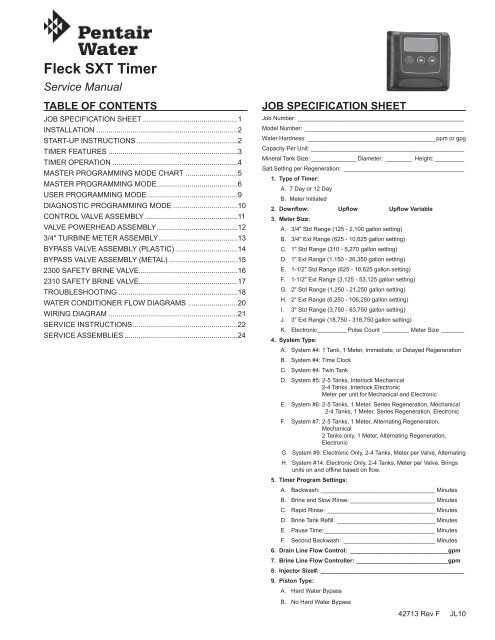
JOB SPECIFICATION SHEET<br />
Job Number:____________________________________________________<br />
Model Number:__________________________________________________<br />
Water Hardness: _______________________________________ ppm or gpg<br />
Capacity Per Unit:________________________________________________<br />
Mineral Tank Size:_______________ Diameter:_ ________ Height:__________<br />
Salt Setting per Regeneration:_ _____________________________________<br />
1. Type of <strong>Timer</strong>:<br />
A. 7 Day or 12 Day<br />
B. Meter Initiated<br />
2. Downflow: Upflow Upflow Variable<br />
3. Meter Size:<br />
A. 3/4" Std Range (125 - 2,100 gallon setting)<br />
B. 3/4" Ext Range (625 - 10,625 gallon setting)<br />
C. 1" Std Range (310 - 5,270 gallon setting)<br />
D. 1" Ext Range (1,150 - 26,350 gallon setting)<br />
E. 1-1/2" Std Range (625 - 10,625 gallon setting)<br />
F. 1-1/2" Ext Range (3,125 - 53,125 gallon setting)<br />
G. 2" Std Range (1,250 - 21,250 gallon setting)<br />
H. 2" Ext Range (6,250 - 106,250 gallon setting)<br />
I. 3" Std Range (3,750 - 63,750 gallon setting)<br />
J. 3" Ext Range (18,750 - 318,750 gallon setting)<br />
K. Electronic_________ Pulse Count_ ________ Meter Size_ _______<br />
4. System Type:<br />
A. System #4: 1 Tank, 1 Meter, Immediate, or Delayed Regeneration<br />
B. System #4: Time Clock<br />
C. System #4: Twin Tank<br />
D. System #5: 2-5 Tanks, Interlock Mechanical<br />
2-4 Tanks, Interlock Electronic<br />
Meter per unit for Mechanical and Electronic<br />
E. System #6: 2-5 Tanks, 1 Meter, Series Regeneration, Mechanical<br />
2-4 Tanks, 1 Meter, Series Regeneration, Electronic<br />
F. System #7: 2-5 Tanks, 1 Meter, Alternating Regeneration,<br />
Mechanical<br />
2 Tanks only, 1 Meter, Alternating Regeneration,<br />
Electronic<br />
G. System #9: Electronic Only, 2-4 Tanks, Meter per Valve, Alternating<br />
H. System #14: Electronic Only, 2-4 Tanks, Meter per Valve. Brings<br />
units on and offline based on flow.<br />
5. <strong>Timer</strong> Program Settings:<br />
A. Backwash:____________________________________ Minutes<br />
B. Brine and Slow Rinse:___________________________ Minutes<br />
C. Rapid Rinse:_ _________________________________ Minutes<br />
D. Brine Tank Refill:_______________________________ Minutes<br />
E. Pause Time:__________________________________ Minutes<br />
F. Second Backwash:_ ____________________________ Minutes<br />
6. Drain Line Flow Control:_ ______________________________gpm<br />
7. Brine Line Flow Controller:_____________________________gpm<br />
8. Injector Size#: ____________________________________________<br />
9. Piston Type:<br />
A. Hard Water Bypass<br />
B. No Hard Water Bypass<br />
42713 Rev F JL10
TIMER FEATURES<br />
Error/<br />
Information<br />
Icon<br />
Parameter<br />
Display<br />
Data<br />
Display<br />
PM<br />
Indicator<br />
Setting the Time of Day<br />
1. Press and hold either the Up or Down buttons until the<br />
programming icon replaces the service icon and the<br />
parameter display reads DO.<br />
2. Adjust the displayed time with the Up and Down buttons.<br />
3. When the desired time is set, press the Extra Cycle button<br />
to resume normal operation. The unit will also return to<br />
normal operation after 5 seconds if no buttons are pressed.<br />
Service<br />
Icon<br />
Programming<br />
Icon<br />
Flow Indicator<br />
x1000 Indicator<br />
Extra Cycle<br />
Button<br />
Up<br />
Button<br />
Figure 1<br />
Down<br />
Button<br />
42637 Rev D<br />
Features of the <strong>SXT</strong>:<br />
• Power backup that continues to keep time and the<br />
passage of days for a minimum of 48 hours in the event<br />
of power failure. During a power outage, the control goes<br />
into a power-saving mode. It does not monitor water<br />
usage during a power failure, but it does store the volume<br />
remaining at the time of power failure.<br />
• Settings for both valve (basic system) and control type<br />
(method used to trigger a regeneration).<br />
• Day-of-the-Week controls.<br />
• While in service, the display alternates between time of<br />
day, volume remaining or days to regeneration, and tank<br />
in service (twin tank systems only).<br />
• The Flow Indicator flashes when outlet flow is detected.<br />
• The Service Icon flashes if a regeneration cycle has been<br />
queued.<br />
• A Regeneration can be triggered immediately by pressing<br />
the Extra Cycle button for five seconds.<br />
• The Parameter Display displays the current Cycle Step<br />
(BW, BF, RR, etc) during regeneration, and the data<br />
display counts down the time remaining for that cycle<br />
step. While the valve is transferring to a new cycle step,<br />
the display will flash. The parameter display will identify<br />
the destination cycle step (BW, BF, RR, etc) and the data<br />
display will read “----”. Once the valve reaches the cycle<br />
step, the display will stop flashing and the data display<br />
will change to the time remaining. During regeneration,<br />
the user can force the control to advance to the next cycle<br />
step immediately by pressing the extra cycle button.<br />
Queueing a Regeneration<br />
1. Press the Extra Cycle button. The service icon will flash to<br />
indicate that a regeneration is queued.<br />
2. To cancel a queued regeneration, press the Extra Cycle<br />
button.<br />
Regenerating Immediately<br />
Press and hold the Extra Cycle button for five seconds.<br />
2 • JL10 <strong>Fleck</strong> <strong>SXT</strong> <strong>Timer</strong>
TIMER OPERATION<br />
Meter Immediate Control<br />
A meter immediate control measures water usage and<br />
regenerates the system as soon as the calculated system<br />
capacity is depleted. The control calculates the system<br />
capacity by dividing the unit capacity (typically expressed in<br />
grains/unit volume) by the feedwater hardness and subtracting<br />
the reserve. Meter Immediate systems generally do not use<br />
a reserve volume. However, in twin tank systems with softwater<br />
regeneration, the reserve capacity should be set to the<br />
volume of water used during regeneration to prevent hard<br />
water break-through. A Meter Immediate control will also start<br />
a regeneration cycle at the programmed regeneration time if<br />
a number of days equal to the regeneration day override pass<br />
before water usage depletes the calculated system capacity.<br />
Meter Delayed Control<br />
A Meter Delayed Control measures water usage and<br />
regenerates the system at the programmed regeneration time<br />
after the calculated system capacity is depleted. As with Meter<br />
Immediate systems, the control calculates the system capacity<br />
by dividing the unit capacity by the feedwater hardness and<br />
subtracting the reserve. The reserve should be set to insure<br />
that the system delivers treated water between the time the<br />
system capacity is depleted and the actual regeneration time. A<br />
Meter Delayed control will also start a regeneration cycle at the<br />
programmed regeneration time if a number of days equal to the<br />
regeneration day override pass before water usage depletes<br />
the calculated system capacity.<br />
Time Clock Delayed Control<br />
A Time Clock Delayed Control regenerates the system on a<br />
timed interval. The control will initiate a regeneration cycle<br />
at the programmed regeneration time when the number of<br />
days since the last regeneration equals the regeneration day<br />
override value.<br />
Day of the Week Control<br />
This control regenerates the system on a weekly schedule.<br />
The schedule is defined in Master Programming by setting<br />
each day to either “off” or “on.” The control will initiates a<br />
regeneration cycle on days that have been set to “on” at the<br />
specified regeneration time.<br />
Control Operation During Regeneration<br />
During regeneration, the control displays a special<br />
regeneration display. In this display, the control shows the<br />
current regeneration step number the valve is advancing to,<br />
or has reached, and the time remaining in that step. The step<br />
number that displays flashes until the valve completes driving<br />
to this regeneration step position. Once all regeneration steps<br />
are complete the valve returns to service and resumes normal<br />
operation.<br />
Pressing the Extra Cycle button during a regeneration cycle<br />
immediately advances the valve to the next cycle step position<br />
and resumes normal step timing.<br />
Manually Initiating a Regeneration<br />
1. When timer is in service, press the Extra Cycle button for 5<br />
seconds on the main screen.<br />
2. The timer advances to Regeneration Cycle Step #1 (rapid<br />
rinse), and begins programmed time count down.<br />
3. Press the Extra Cycle button once to advance valve to<br />
Regeneration Cycle Step #2 (backwash).<br />
4. Press the Extra Cycle button once to advance valve to<br />
Regeneration Cycle Step #3 (brine draw & slow rinse).<br />
5. Press the Extra Cycle button once to advance valve to<br />
Regeneration Cycle Step #4 (brine refill).<br />
6. Press the Extra Cycle button once more to advance the<br />
valve back to in service.<br />
NOTE: If the unit is a filter or upflow, the cycle step<br />
order may change.<br />
NOTE: A queued regeneration can be initiated by<br />
pressing the Extra Cycle button. To clear a<br />
queued regeneration, press the Extra Cycle<br />
button again to cancel. If regeneration occurs<br />
for any reason prior to the delayed regeneration<br />
time, the <strong>manual</strong> regeneration request shall be<br />
cleared.<br />
Control Operation During A Power Failure<br />
The <strong>SXT</strong> includes integral power backup. In the event of power<br />
failure, the control shifts into a power-saving mode. The control<br />
stops monitoring water usage, and the display and motor shut<br />
down, but it continues to keep track of the time and day for a<br />
minimum of 48 hours.<br />
The system configuration settings are stored in a non-volatile<br />
memory and are stored indefinitely with or without line power.<br />
The Time of Day flashes when there has been a power failure.<br />
Press any button to stop the Time of Day from flashing.<br />
If power fails while the unit is in regeneration, the control will<br />
save the current valve position before it shuts down. When<br />
power is restored, the control will resume the regeneration<br />
cycle from the point where power failed. Note that if power fails<br />
during a regeneration cycle, the valve will remain in it’s current<br />
position until power is restored. The valve system should<br />
include all required safety components to prevent overflows<br />
resulting from a power failure during regeneration.<br />
The control will not start a new regeneration cycle without line<br />
power. If the valve misses a scheduled regeneration due to<br />
a power failure, it will queue a regeneration. Once power is<br />
restored, the control will initiate a regeneration cycle the next<br />
time that the Time of Day equals the programmed regeneration<br />
time. Typically, this means that the valve will regenerate one<br />
day after it was originally scheduled. If the treated water<br />
output is important and power interruptions are expected, the<br />
system should be setup with a sufficient reserve capacity to<br />
compensate for regeneration delays.<br />
Control Operation During Programming<br />
The control only enters the Program Mode with the valve in<br />
service. While in the Program Mode, the control continues<br />
to operate normally monitoring water usage and keeping all<br />
displays up to date. Control programming is stored in memory<br />
permanently, eliminating the need for battery backup power.<br />
<strong>Fleck</strong> <strong>SXT</strong> <strong>Timer</strong> JL10 • 3
MASTER PROGRAMMING MODE<br />
CHART<br />
Caution: Before entering Master Programming, please<br />
contact your local professional water dealer.<br />
Master Programming Options<br />
Abbreviation Parameter Option<br />
Options<br />
Abbreviation<br />
GAL Gallons<br />
DF<br />
Display Format<br />
Ltr Liters<br />
dF1b Standard Downflow/Upflow Single Backwash<br />
dF2b Standard Downflow/Upflow Double Backwash<br />
Fltr Filter<br />
VT<br />
Valve Type<br />
UFbd Upflow Brine First<br />
8500 TwinFlo100<strong>SXT</strong><br />
Othr Other<br />
Fd Meter (Flow) Delayed<br />
FI Meter (Flow) Immediate<br />
CT<br />
Control Type<br />
tc Time Clock<br />
dAY Day of Week<br />
1 Single Tank System<br />
NT<br />
Number of Tanks<br />
2 Two Tank System<br />
U1 Tank 1 in Service<br />
TS<br />
Tank in Service<br />
U2<br />
Tank 2 in Service<br />
C Unit Capacity Unit Capacity (Grains)<br />
H Feedwater Hardness Hardness of Inlet Water<br />
RS<br />
Reserve Selection SF Percentage Safety Factor<br />
rc Fixed Reserve Capacity<br />
SF Safety Factor Percentage of the system capacity to be used as a reserve<br />
RC Fixed Reserve Capacity Fixed volume to be used as a reserve<br />
DO Day Override The system’s day override setting<br />
RT Regen Time The time of day the system will regenerate<br />
BW, BD, RR, BF Regen Cycle Step Times<br />
The time duration for each regeneration step. Adjustable from OFF and<br />
0-199 minutes.<br />
NOTE: If “Othr” is chosen under “Valve Type”, then R1, R2, R3,<br />
etc, will be displayed instead<br />
D1, D2, D3, D4, D5,<br />
D6, & D7<br />
Day of Week Settings<br />
Regeneration setting (On or OFF) for each day of the week on day-ofweek<br />
systems<br />
CD Current Day The Current day of the week<br />
t0.7 3/4” Turbine Meter<br />
P0.7 3/4” Paddle Wheel Meter<br />
t1.0 1” Turbine Meter<br />
FM<br />
Flow Meter Type<br />
P1.0 1” Paddle Wheel Meter<br />
t1.5 1.5” Turbine Meter<br />
P1.5 1.5” Paddle Wheel Meter<br />
P2.0 2” Paddle Wheel Meter<br />
Gen Generic or Other Meter<br />
K Meter Pulse Setting Meter pulses per gallon for generic/other flow meter<br />
Notes: Some items may not be shown depending on timer<br />
configuration. The timer will discard any changes<br />
and exit Master Programming Mode if any button is<br />
not pressed for sixty seconds.<br />
4 • JL10 <strong>Fleck</strong> <strong>SXT</strong> <strong>Timer</strong>
MASTER PROGRAMMING MODE<br />
When the Master Programming Mode is entered, all available<br />
option setting displays may be viewed and set as needed.<br />
Depending on current option settings, some parameters cannot<br />
be viewed or set.<br />
Setting the Time of Day<br />
1. Press and hold either the Up or Down buttons until the<br />
programming icon replaces the service icon and the<br />
parameter display reads DO.<br />
2. Adjust the displayed time with the Up and Down buttons.<br />
3. When the desired time is set, press the Extra Cycle button<br />
to resume normal operation. The unit will also return to<br />
normal operation after 5 seconds if no buttons are pressed.<br />
Entering Master Programming Mode<br />
Set the Time Of Day display to 12:01 P.M. Press the Extra<br />
Cycle button (to exit Setting Time of Day mode). Then<br />
press and hold the Up and Down buttons together until the<br />
programming icon replaces the service icon and the Display<br />
Format screen appears.<br />
Exiting Master Programming Mode<br />
Press the Extra Cycle button to accept the displayed settings<br />
and cycle to the next parameter. Press the Extra Cycle<br />
button at the last parameter to save all settings and return to<br />
normal operation. The control will automatically disregard any<br />
programming changes and return to normal operation if it is<br />
left in Master Programming mode for 5 minutes without any<br />
keypad input.<br />
Resets<br />
Soft Reset: Press and hold the Extra Cycle and Down buttons<br />
for 25 seconds while in normal Service mode. This resets all<br />
parameters to the system default values, except the volume<br />
remaining in meter immediate or meter delayed systems and<br />
days since regeneration in the time clock system.<br />
Master Reset: Hold the Extra Cycle button while powering up<br />
the unit. This resets all of the parameters in the unit. Check<br />
and verify the choices selected in Master Programming Mode.<br />
1. Display Format (Display Code DF)<br />
This is the first screen that appears when entering Master<br />
Programming Mode. The Display Format setting specifies<br />
the unit of measure that will be used for volume and how<br />
the control will display the Time of Day. This option setting is<br />
identified by “DF” in the upper left hand corner of the screen.<br />
There are three possible settings:<br />
2. Valve Type (Display Code VT)<br />
Press the Extra Cycle button. Use this display to set the<br />
Valve Type. The Valve Type setting specifies the type of<br />
cycle that the valve follows during regeneration. Note that<br />
some valve types require that the valve be built with specific<br />
subcomponents. Ensure the valve is configured properly before<br />
changing the Valve Type setting. This option setting is identified<br />
by “VT” in the upper left hand corner of the screen. There are 5<br />
possible settings:<br />
Abbreviation<br />
Parameter<br />
dF1b Standard Downflow/Upflow, Single Backwash<br />
dF2b Standard Downflow/Upflow, Double Backwash<br />
Fltr<br />
Filter<br />
UFbd<br />
Upflow Brine First<br />
8500 TwinFlo 100<br />
Othr<br />
Other<br />
3. Control Type (Display Code CT)<br />
Press the Extra Cycle button. Use this display to set the<br />
Control Type. This specifies how the control determines when<br />
to trigger a regeneration. For details on how the various<br />
options function, refer to the “<strong>Timer</strong> Operation” section of this<br />
service <strong>manual</strong>. This option setting is identified by “CT” in the<br />
upper left hand corner of the screen. There are four possible<br />
settings:<br />
Meter Delayed: Fd<br />
Meter Immediate: FI<br />
Time Clock: tc<br />
Day of Week: dAY<br />
4. Number of Tanks (Display Code NT)<br />
Press the Extra Cycle button. Use this display to set the<br />
Number of Tanks in your system. This option setting is<br />
identified by “NT” in the upper left hand corner of the screen.<br />
There are two possible settings:<br />
Single Tank System: 1<br />
Two-Tank System: 2<br />
Display Format Setting Unit of Volume Time Display<br />
GAL U.S. Gallons 12-Hour AM/PM<br />
Ltr Liters 24-Hour<br />
<strong>Fleck</strong> <strong>SXT</strong> <strong>Timer</strong> JL10 • 5
MASTER PROGRAMMING MODE<br />
continued<br />
5. Tank in Service (Display Code TS)<br />
Press the Extra Cycle button. Use this display to set whether<br />
tank one or tank two is in service. This option setting is<br />
identified by “TS” in the upper left hand corner of the screen.<br />
This parameter is only available if the number of tanks has<br />
been set to 2. There are two possible settings:<br />
Tank One in Service: U1<br />
Tank Two in Service: U2<br />
9. Safety Factor (Display Code SF)<br />
Press the Extra Cycle button. Use this display to set the<br />
Safety Factor. This setting specifies what percentage of the<br />
system capacity will be held as a reserve. Since this value is<br />
expressed as a percentage, any change to the unit capacity<br />
or feedwater hardness that changes the calculated system<br />
capacity will result in a corresponding change to the reserve<br />
volume.This option setting is identified by “SF” in the upper left<br />
hand corner of the screen. Use the Up and Down buttons to<br />
adjust the value from 0 to 50% as needed.<br />
6. Unit Capacity (Display Code C)<br />
Press the Extra Cycle button. Use this display to set the Unit<br />
Capacity. This setting specifies the treatment capacity of the<br />
system media. Enter the capacity of the media bed in grains<br />
of hardness when configuring a softener system, and in the<br />
desired volume capacity when configuring a filter system. This<br />
option setting is identified by “C” in the upper left hand corner<br />
of the screen. The Unit Capacity parameter is only available<br />
if the control type has been set to one of the metered options.<br />
Use the Up and Down buttons to adjust the value as needed.<br />
Range: 0-50%<br />
10. Fixed Reserve Capacity (Display Code RC)<br />
Press the Extra Cycle button. Use this display to set the<br />
Reserve Capacity. This setting specifies a fixed volume that will<br />
be held as a reserve. The reserve capacity cannot be set to a<br />
value greater than one-half of the calculated system capacity.<br />
The reserve capacity is a fixed volume and does not change<br />
if the unit capacity or feedwater hardness are changed. This<br />
option setting is identified by “RC” in the upper left-hand corner<br />
of the screen. Use the Up and Down buttons to adjust the<br />
value as needed.<br />
Range: 1-999,900 gallons (100-9,999,000 Liters)<br />
7. Feedwater Hardness (Display Code H)<br />
Press the Extra Cycle button. Use this display to set the<br />
Feedwater Hardness. Enter the feedwater hardness in grains<br />
per unit volume for softener systems, or 1 for filter systems.<br />
This option setting is identified by “H” in the upper left hand<br />
corner of the screen. The feedwater hardness parameter is<br />
only available if the control type has been set to one of the<br />
metered options. Use the Up and Down buttons to adjust the<br />
value as needed.<br />
Range: 0-half the calculated capacity<br />
11. Day Override (Display Code DO)<br />
Press the Extra Cycle button. Use this display to set the Day<br />
Override. This setting specifies the maximum number of days<br />
between regeneration cycles. If the system is set to a timertype<br />
control, the day override setting determines how often<br />
the system will regenerate. A metered system will regenerate<br />
regardless of usage if the days since last regeneration cycle<br />
equal the day override setting. Setting the day override value<br />
to “OFF” disables this function. This option setting is identified<br />
by “DO” in the upper left hand corner of the screen. Use the Up<br />
and Down buttons to adjust the value as needed.<br />
Range: 1-199 hardness<br />
8. Reserve Selection (Display Code RS)<br />
Press the Extra Cycle button. Use this display to set the Safety<br />
Factor. Use this display to select the type of reserve to be used<br />
in your system. This setting is identified by “RS” in the upper<br />
left-hand corner of the screen. The reserve selection parameter<br />
is only available if the control type has been set to one of the<br />
metered options. There are two possible settings.<br />
Range: Off-99 days<br />
FS<br />
rc<br />
Safety Factor<br />
Fixed Reserve Capacity<br />
6 • JL10 <strong>Fleck</strong> <strong>SXT</strong> <strong>Timer</strong>
MASTER PROGRAMMING MODE<br />
continued<br />
12. Regeneration Time<br />
Press the Extra Cycle button. Use this display to set the<br />
Regeneration Time. This setting specifies the time of day the<br />
control will initiate a delayed, <strong>manual</strong>ly queued, or day override<br />
triggered regeneration. This option setting is identified by “RT”<br />
in the upper left hand corner of the screen. Use the Up and<br />
Down buttons to adjust the value as needed.<br />
15. Current Day (Display Code CD)<br />
Press the Extra Cycle button. Use this display to set the current<br />
day on systems that have been configured as Day of Week<br />
controls. This setting is identified by “CD” in the upper left-hand<br />
corner of the screen. Use the Up and Down buttons to select<br />
from Day 1 through Day 7.<br />
13. Regeneration Cycle Step Times<br />
Press the Extra Cycle button. Use this display to set the<br />
Regeneration Cycle Step Times. The different regeneration<br />
cycles are listed in sequence based on the valve type selected<br />
for the system, and are identified by an abbreviation in the<br />
upper left-hand corner of the screen. The abbreviations used<br />
are listed below. If the system has been configured with the<br />
“OTHER” valve type, the regeneration cycles will be identified<br />
as R1, R2, R3, R4, R5, and R6. Each cycle step time can be<br />
set from 0 to 199 minutes. Setting a cycle step time to 0 will<br />
cause the control to skip that step during regeneration, but<br />
keeps the following steps available. Use the Up and Down<br />
buttons to adjust the value as needed. Press the Extra Cycle<br />
button to accept the current setting and move to the next<br />
parameter.<br />
Abbreviation<br />
BD<br />
BF<br />
BW<br />
RR<br />
SV<br />
Cycle Step<br />
Brine Draw<br />
Brine Fill<br />
Backwash<br />
Rapid Rinse<br />
Service<br />
16. Flow Meter Type (Display Code FM)<br />
Press the Extra Cycle button. Use this display to set the type<br />
of flow meter connected to the control. This option setting is<br />
identified by “FM” in the upper left-hand corner of the screen.<br />
Use the Up and Down buttons to select one of the 7 available<br />
settings.<br />
t0.7 <strong>Fleck</strong> 3/4” Turbine Meter<br />
P0.7 <strong>Fleck</strong> 3/4” Paddle Wheel Meter<br />
t1.0 <strong>Fleck</strong> 1” Turbine Meter<br />
P1.0 <strong>Fleck</strong> 1” Paddle Wheel Meter<br />
t1.5 <strong>Fleck</strong> 1 1/2” Turbine Meter<br />
P1.5 <strong>Fleck</strong> 1 1/2” Paddle Wheel Meter<br />
P2.0 <strong>Fleck</strong> 2” Paddle Wheel Meter<br />
GEn<br />
Generic/Other Meter<br />
17. Meter Pulse Setting (Display Code K)<br />
Press the Extra Cycle button. Use this display to specify the<br />
meter pulse setting for a non-standard flow meter. This option<br />
setting is identified by “K” in the upper left-hand corner of<br />
the screen. Use the Up and Down buttons to enter the meter<br />
constant in pulses per unit volume.<br />
Range: 0-199 minutes<br />
14. Day of Week Settings<br />
Press the Extra Cycle button. Use this display to set the<br />
regeneration schedule for a system configured as a Day of<br />
Week control. The different days of the week are identified as<br />
D1, D2, D3, D4, D5, D6, and D7 in the upper left-hand corner<br />
of the display. Set the value to “ON” to schedule a regeneration<br />
or “OFF” to skip regeneration for each day. Use the Up and<br />
Down buttons to adjust the setting as needed. Press the Extra<br />
Cycle button to accept the setting and move to the next day.<br />
Note that the control requires at least one day to be set to<br />
“ON.” If all 7 days are set to “OFF”, the unit will return to Day<br />
One until one or more days are set to “ON.”<br />
18. End of Master Programming Mode<br />
Press the Extra Cycle button to save all settings and exit<br />
Master Programming Mode.<br />
<strong>Fleck</strong> <strong>SXT</strong> <strong>Timer</strong> JL10 • 7
USER PROGRAMMING MODE<br />
User Programming Mode Options<br />
Abbreviation Parameter Description<br />
DO Day Override The timer’s day override setting<br />
RT<br />
H<br />
Regeneration<br />
Time<br />
Feed Water<br />
Hardness<br />
The time of day that the system<br />
will regenerate (meter delayed,<br />
timeclock, and day-of-week<br />
systems)<br />
The hardness of the inlet water<br />
- used to calculate system<br />
capacity for metered systems<br />
RC or SF Reserve Capacity The fixed reserve capacity<br />
CD Current Day The current day of week<br />
6. Press the Extra Cycle button. Use this display to set the<br />
Current Day of the Week. This option setting is identified by<br />
“CD” in the upper left hand corner of the screen.<br />
7. Press the Extra Cycle button to end User Programming<br />
Mode.<br />
NOTE: Some items may not be shown depending on timer<br />
configuration. The timer will discard any changes<br />
and exit User Mode if any button is not pressed for<br />
sixty seconds.<br />
User Programming Mode Steps<br />
1. Press the Up and Down buttons for five seconds while in<br />
service, and the time of day is NOT set to 12:01 PM.<br />
2. Use this display to adjust the Day Override. This option<br />
setting is identified by “DO” in the upper left hand corner of<br />
the screen.<br />
3. Press the Extra Cycle button. Use this display to adjust the<br />
Regeneration Time. This option setting is identified by “RT”<br />
in the upper left hand corner of the screen.<br />
4. Press the Extra Cycle button. Use this display to adjust the<br />
Feed Water Hardness. This option setting is identified by<br />
“H” in the upper left hand corner of the screen.<br />
Range: 1-199 hardness<br />
5. Press the Extra Cycle button. Use this display to adjust the<br />
Fixed Reserve Capacity. This option setting is identified by<br />
“RC” or "SF" in the upper left-hand Corner of the screen.<br />
8 • JL10 <strong>Fleck</strong> <strong>SXT</strong> <strong>Timer</strong>
DIAGNOSTIC PROGRAMMING MODE<br />
Diagnostic Programming Mode Options<br />
Abbreviation Parameter Description<br />
FR Flow Rate Displays the current outlet flow rate<br />
PF<br />
HR<br />
Peak Flow<br />
Rate<br />
Hours in<br />
Service<br />
Displays the highest flow<br />
rate measured since the last<br />
regeneration<br />
Displays the total hours that the unit<br />
has been in service<br />
VU Volume Used Displays the total volume of water<br />
treated by the unit<br />
RC<br />
SV<br />
Reserve<br />
Capacity<br />
Software<br />
Version<br />
Displays the system’s reserve<br />
capacity calculated from the system<br />
capacity, feedwater hardness, and<br />
safety factor<br />
Displays the software version<br />
installed on the controller<br />
NOTE: Some items may not be shown depending on timer<br />
configuration. The timer will exit Diagnostic Mode<br />
after 60 seconds if no buttons are pressed. Press<br />
the Extra Cycle button to exit Diagnostic Mode at<br />
any time.<br />
6. Press the Up button. Use this display to view the Reserve<br />
Capacity. This option setting is identified by “RC” in the<br />
upper left hand corner of the screen.<br />
7. Press the Up button. Use this display to view the Software<br />
Version. This option setting is identified by “SV” in the upper<br />
left hand corner of the screen.<br />
8. Press the Extra Cycle button to end Diagnostic<br />
Programming Mode.<br />
Diagnostic Programming Mode Steps<br />
1. Press the Up and Extra Cycle buttons for five seconds<br />
while in service.<br />
2. Use this display to view the current Flow Rate. This option<br />
setting is identified by “FR” in the upper left hand corner of<br />
the screen.<br />
3. Press the Up button. Use this display to view the Peak Flow<br />
Rate since the last regeneration cycle. This option setting<br />
is identified by “PF” in the upper left hand corner of the<br />
screen.<br />
4. Press the Up button. Use this display to view the Hours<br />
in Service since the last regeneration cycle. This option<br />
setting is identified by “HR” in the upper left hand corner of<br />
the screen.<br />
5. Press the Up button. Use this display to view the Volume<br />
Used since the last regeneration cycle. This option setting<br />
is identified by “VU” in the upper left hand corner of the<br />
screen.<br />
<strong>Fleck</strong> <strong>SXT</strong> <strong>Timer</strong> JL10 • 9
2510/2750/2850S TIMER ASSEMBLY<br />
3 4<br />
1<br />
8<br />
2<br />
7<br />
5<br />
9<br />
9A<br />
9B<br />
9E<br />
9C 9D<br />
42778 Rev E<br />
Item No. QTY Part No. Description<br />
1 ................1 ....... 13881 ................Bracket, Hinge <strong>Timer</strong><br />
3 ................1 ....... 14265 ................Clip, Spring<br />
4 ................1 ....... 27172 ................Stand-off, <strong>Timer</strong>, 2510<strong>SXT</strong>,<br />
2750<strong>SXT</strong><br />
5 ................1 ....... 21363 ................Screw, Hex HD, M4 X 12 MM<br />
7 ................1 ....... 27168 ................Bracket, <strong>Timer</strong>,<br />
2510SE/2750<strong>SXT</strong><br />
8 ................3 ....... 13296 ................Screw, Hex Washer, 6-20 X 1/2<br />
9 ................1 ....... 42778 ................<strong>Timer</strong>, <strong>SXT</strong>, 2510/2750, DF<br />
9A .............1 ....... 19889 ................Housing, Circuit Board<br />
9B .............1 ....... 42196 ................Circuit Board, <strong>SXT</strong><br />
9C .............1 ....... 42635-01 ...........Cover, Front, <strong>SXT</strong>, Square<br />
9D .............1 ....... 42637 ................Label, Display, <strong>SXT</strong><br />
9E .............1 ....... 42864 ................Wire Harness, <strong>SXT</strong><br />
10 • JL10 <strong>Fleck</strong> <strong>SXT</strong> <strong>Timer</strong>
9000/9100/9500 TWIN TANK TIMER<br />
ASSEMBLY<br />
1<br />
5 6<br />
2<br />
7<br />
4<br />
3<br />
7A<br />
7B<br />
8<br />
7C<br />
7D<br />
42777 Rev D<br />
Item No. QTY Part No. Description<br />
1 ................1 ....... 13881 ................Bracket, Hinge <strong>Timer</strong><br />
2 ................2 ....... 11384 ................Screw, Phillips, 6-32 X 1/4<br />
3 ................1 ....... 42732 ................Bracket, <strong>Timer</strong>, 9000<strong>SXT</strong><br />
4 ................2 ....... 13296 ................Screw, Hex Washer Hd, 6-20 X<br />
1/2<br />
5 ................1 ....... 14265 ................Clip, Spring<br />
6 ................1 ....... 42733 ................Stand-off, <strong>Timer</strong>, 9000<strong>SXT</strong><br />
7 ................1 ....... 42777 ................<strong>Timer</strong>, <strong>SXT</strong>, D/F, 9000/9100/9500<br />
7A .............1 ....... 19889 ................Housing, Circuit Board<br />
7B .............1 ....... 42196 ................Circuit Board, <strong>SXT</strong><br />
7C .............1 ....... 42635-01 ...........Cover, Front, <strong>SXT</strong>, Square<br />
7D .............1 ....... 42637 ................Label, Display, <strong>SXT</strong><br />
8 ................1 ....... 19474-01 ...........Harness, <strong>SXT</strong><br />
<strong>Fleck</strong> <strong>SXT</strong> <strong>Timer</strong> JL10 • 11
3/4" PLASTIC TURBINE METER<br />
ASSEMBLY<br />
19797 Rev A<br />
Item No. QTY Part No. Description<br />
1 ................1 ....... 19791-01 ...........Meter Cable Assy, Turbine/<strong>SXT</strong><br />
2 ................2 ....... 19569 ................Clip, Flow Meter<br />
3 ................2 ....... 13314 ................Screw, Slot Ind Hex, 8-18 x .60<br />
12 • JL10 <strong>Fleck</strong> <strong>SXT</strong> <strong>Timer</strong>
METER ASSEMBLY<br />
60086 Rev D<br />
Item No. QTY Part No. Description<br />
1 ................1 ....... 13874 ................Body, Meter, 5600<br />
2 ................1 ....... 14715 ................Gear Assy, Electronic Meter Cap<br />
3 ................1 ....... 41055 ................Plate, Intermediate<br />
4 ................1 ....... 13847 ................O-ring, -137, Std, Meter<br />
5 ................5 ....... 17798 ................Screw, Slot Hex Washer Head<br />
6 ................1 ....... 13821 ................Body, Meter, 5600<br />
7 ................1 ....... 13509 ................Impeller, Meter<br />
8 ................4 ....... 12473 ................Screw, Hex Wsh, 10-24 x 5/8<br />
9 ................4 ....... 13255 ................Clip, Mounting<br />
10 ..............1 ....... 13314 ................Screw, Slot Ind Hex, 8-18 x .60<br />
11 ..............1 ....... 13305 ................O-ring, -119<br />
12 ..............1 ....... 14613 ................Flow Straightener<br />
<strong>Fleck</strong> <strong>SXT</strong> <strong>Timer</strong> JL10 • 13
3/4" BRASS PADDLE METER<br />
ASSEMBLY<br />
60618 Rev B<br />
Item No. QTY Part No. Description<br />
1 ................1 ....... 11206 ................Gasket, Fitting<br />
2 ................1 ....... 13942 ................Retainer, Nut<br />
3 ................1 ....... 11207 ................Nut, Special, Quick Connect<br />
4 ................1 ....... 13906 ................Body, Meter, 3/4"<br />
5 ................1 ....... 13509 ................Impeller, Meter<br />
............................ 13509-01 ...........Impeller, Celcon<br />
6 ................1 ....... 13847 ................O-ring, -137 Std/560CD, Meter<br />
7 ................1 ....... 14716 ................Meter Cap Assy, ET/NT<br />
8 ................1 ....... 12473 ................Screw, Hex Wsh, 10-24 x 5/8<br />
Not Shown<br />
........ 19121-08 ...........Meter Cable Assy, NT, 35" w/<br />
Connector<br />
........ 19121-09 ...........Meter Cable Assy, NT, 99.5" w/<br />
Connector<br />
........ 19121-10 ...........Meter Cable Assy, NT, 303.5" w/<br />
Connector<br />
14 • JL10 <strong>Fleck</strong> <strong>SXT</strong> <strong>Timer</strong>
1" BRASS PADDLE METER ASSEMBLY<br />
60027 Rev D<br />
Item No. QTY Part No. Description<br />
1 ................1 ....... 14959 ................Body, Meter, 2750<br />
2 ................1 ....... 13882 ................Post, Meter Impeller<br />
3 ................1 ....... 13509 ................Impeller, Meter<br />
4 ................1 ....... 13847 ................O-ring, -137, Std/560CD, Meter<br />
5 ................1 ....... 14716 ................Meter Cap Assy, ET/NT<br />
6 ................4 ....... 12112 ................Screw, Hex Hd Mach, 10-24 x<br />
1/2<br />
7 ................1 ....... 14960 ................Flow Straightener, 1"<br />
8 ................1 ....... 13287 ................O-ring, -123<br />
9 ................1 ....... 14961 ................Fitting, 1" Quick Connect<br />
10 ..............1 ....... 14962 ................Nut, 1" Meter, Quick Connect<br />
<strong>Fleck</strong> <strong>SXT</strong> <strong>Timer</strong> JL10 • 15
INLINE PLASTIC TURBINE METER<br />
ASSEMBLY<br />
61560 Rev D<br />
Item No. QTY Part No. Description<br />
1 ................1 ....... 17542 ................Flow Straightener<br />
2 ................2 ....... 40576 ................Clip, H, Plastic, 7000<br />
3 ................1 ....... 40577 ................Turbine Meter Assy, 7000<br />
4 ................1 ....... 41555 ................Body, Remote Meter<br />
5 ................2 ....... 40951 ................O-ring, -220<br />
6 ................2 ....... 40563 ................Connector, 1" NPT, 7000<br />
7 ................2 ....... 40563-10 ...........Connector, 1" BSP, 7000<br />
8 ................2 ....... 40565 ................Connector, 1-1/4" NPT, 7000<br />
9 ................2 ....... 40565-10 ...........Connector, 1-1/4" BSP, 7000<br />
10 ..............2 ....... 41242 ................Connector, 1" & 1-1/4" Sweat<br />
11 ..............2 ....... 41243 ................Connector, 1-1/4 & 1-1/2" Sweat<br />
12 ..............2 ....... 41596 ................Connector, Brass, 1" NPT<br />
13 ..............2 ....... 41596-10 ...........Connector, Brass, 1" BSP<br />
14 ..............2 ....... 41597 ................Connector, Brass, 1-1/2" NPT<br />
15 ..............2 ....... 41597-10 ...........Connector, Brass, 1-1/2" BSP<br />
16 • JL10 <strong>Fleck</strong> <strong>SXT</strong> <strong>Timer</strong>
1-1/2" BRASS PADDLE METER<br />
ASSEMBLY<br />
60614 Rev B<br />
Item No. QTY Part No. Description<br />
1 ................1 ....... 17569 ................Body, Meter, 2850/9500<br />
2 ................1 ....... 13882 ................Post, Meter Impeller<br />
3 ................1 ....... 13509 ................Impeller, Meter<br />
4 ................1 ....... 13847 ................O-ring, -137, Std/560CD, Meter<br />
5 ................1 ....... 14716 ................Meter Cap Assy, NT<br />
6 ................4 ....... 12112 ................Screw, Hex Hd Mach, 10-24 x<br />
1/2<br />
7 ................1 ....... 17542 ................Flow Straightener, 1-1/2"<br />
8 ................1 ....... 12733 ................O-ring, -132<br />
9 ................1 ....... 17544 ................Fitting, 1-1/2" Quick Connect<br />
10 ..............1 ....... 17543 ................Nut, 1-1/2", Quick Connect<br />
<strong>Fleck</strong> <strong>SXT</strong> <strong>Timer</strong> JL10 • 17
3/4", 1" or 1-1/2" PADDLE WHEEL<br />
METER CAP ASSEMBLY<br />
Item No. QTY Part No. Description<br />
1 ................1 ....... 14716 ................Meter Cap Assy, NT<br />
2 ................1 ....... 19121-01 ...........Meter Cable Assy, <strong>SXT</strong>, Paddle<br />
6700XTR<br />
3 ................1 ....... 13847 ................O-ring, -137, Std/560CD, Meter<br />
4 ................1 ....... 17798 ................Screw, Slot Hex Wsh Hd<br />
18 • JL10 <strong>Fleck</strong> <strong>SXT</strong> <strong>Timer</strong>
TROUBLESHOOTING<br />
Error Codes<br />
NOTE: Error codes appear on the In Service display.<br />
Error Code Error Type Cause Reset and Recovery<br />
0 Cam Sense<br />
Error<br />
The valve drive took longer than<br />
6 minutes to advance to the next<br />
regeneration position<br />
Unplug the unit and examine the powerhead. Verify that all cam switches are<br />
connected to the circuit board and functioning properly. Verify that the motor<br />
and drive train components are in good condition and assembled properly.<br />
Check the valve and verify that the piston travels freely. Replace/reassemble<br />
the various components as necessary.<br />
1 Cycle Step<br />
Error<br />
2 Regen<br />
Failure<br />
3 Memory<br />
Error<br />
UD<br />
Upper Drive<br />
Sync<br />
The control experienced an<br />
unexpected cycle input<br />
The system has not regenerated<br />
for more than 99 days (or 7 days<br />
if the Control Type has been set to<br />
Day-of-Week)<br />
Control board memory failure<br />
Power failure install programming<br />
change<br />
Plug the unit back in and observe its behavior. The unit should cycle to<br />
the next valve position and stop. If the error re-occurs, unplug the unit and<br />
contact technical support.<br />
Unplug the unit and examine the powerhead. Verify that all cam switches<br />
are connected to the circuit board and functioning properly. Enter Master<br />
Programming mode and verify that the valve type and system type are set<br />
correctly with regard to the unit itself.<br />
Step the unit through a <strong>manual</strong> regeneration and verify that it functions<br />
correctly. If the error re-occurs unplug the unit and contact technical support.<br />
Perform a Manual Regeneration to reset the error code.<br />
If the system is metered, verify that it is measuring flow by running service<br />
water and watching for the flow indicator on the display. If the unit does not<br />
measure flow, verify that the meter cable is connected properly and that the<br />
meter is functioning properly.<br />
Enter a Master Programming Mode and verify that the unit is configured<br />
properly. As appropriate for the valve configuration, check that the correct<br />
system capacity has been selected, that the day override is set properly,<br />
and that meter is identified correctly. If the unit is configured as a Day-of-<br />
Week system, verify that at least one day is set ON. Correct the settings as<br />
necessary.<br />
Perform a Master Reset and reconfigure the system via Master Programming<br />
Mode. After reconfiguring the system, step the valve through a <strong>manual</strong><br />
regeneration. If the error re-occurs unplug the unit and contact technical<br />
support.<br />
Valve will automatically recover.<br />
<strong>Fleck</strong> <strong>SXT</strong> <strong>Timer</strong> JL10 • 19
2510<strong>SXT</strong> WIRING DIAGRAM<br />
HCAM<br />
SCAM<br />
SW1<br />
C<br />
N.O.<br />
N.C.<br />
C<br />
SW2<br />
N.O.<br />
N.C.<br />
VDM<br />
H/S<br />
P2<br />
P1<br />
PWR VDO METER<br />
H N N N.O. H - - S<br />
TM<br />
PURPLE<br />
ORANGE<br />
WHITE<br />
GREEN<br />
BLUE<br />
WHITE<br />
YEL<br />
WT/BLK<br />
S<br />
+<br />
BLACK<br />
ORANGE<br />
BLACK<br />
PURPLE<br />
BLACK<br />
BLUE<br />
WT/BLK<br />
YELLOW<br />
BLACK<br />
RED<br />
NOTE:<br />
1.<br />
2.<br />
T1<br />
BACKPLATE<br />
GROUND<br />
SCREW<br />
3.<br />
DEPENDING ON APPLICATION, VALVE STEP CAM APPEARANCE WILL VARY.<br />
REGARDLESS OF CAM TYPE USED, WIRING TO SWITCHES SW1 AND SW2<br />
WILL REMAIN AS SHOWN.<br />
VALVE SHOWN IN SERVICE POSITION.<br />
CB1<br />
50/60 HZ<br />
GREEN/YELLOW<br />
BLACK (BROWN)<br />
WHITE (BLUE)<br />
CB1 - <strong>SXT</strong> TIMER<br />
T1 - 24VAC TRANSFORMER<br />
K1 - 24VAC VALVE DRIVE RELAY<br />
TM - 3/4" TURBINE FLOW METER (OPTIONAL)<br />
VDM - VALVE DRIVE MOTOR<br />
SW1 - VALVE HOMING SWITCH<br />
SW2 - VALVE STEP SWITCH<br />
HCAM - VALVE HOMING CAM<br />
SCAM - VALVE STEP CAM<br />
42741 Rev B<br />
20 • JL10 <strong>Fleck</strong> <strong>SXT</strong> <strong>Timer</strong>
2750<strong>SXT</strong>/2850<strong>SXT</strong> WIRING DIAGRAM<br />
SW2<br />
C<br />
C<br />
N.O.<br />
N.C.<br />
N.O.<br />
N.C.<br />
VDM<br />
HCAM<br />
SW1<br />
SCAM<br />
H/S<br />
P2<br />
P1<br />
PWR VDO METER<br />
H N N N.O. H - - S<br />
1.0"<br />
PWM<br />
BLACK<br />
ORANGE<br />
BLACK<br />
PURPLE<br />
ORANGE<br />
WHITE<br />
GREEN<br />
YEL<br />
WT/BLK<br />
CB1<br />
50/60 HZ<br />
S<br />
+<br />
PURPLE<br />
BLACK<br />
BLUE<br />
WT/BLK<br />
YELLOW<br />
BLACK<br />
RED<br />
NOTE:<br />
1. DEPENDING ON APPLICATION, VALVE STEP CAM APPEARANCE<br />
WILL VARY.<br />
2.<br />
3.<br />
T1<br />
BACKPLATE<br />
GROUND<br />
SCREW<br />
REGARDLESS OF CAM TYPE USED, WIRING TO SWITCHES SW1<br />
AND SW2 WILL REMAIN AS SHOWN.<br />
VALVE SHOWN IN SERVICE POSITION.<br />
GREEN/YELLOW<br />
BLUE<br />
BLACK (BROWN)<br />
WHITE<br />
WHITE (BLUE)<br />
CB1 - <strong>SXT</strong> TIMER<br />
T1 - 24VAC TRANSFORMER<br />
K1 - 24VAC VALVE DRIVE RELAY<br />
PWM - 1.0" OR 1.5" PADDLE WHEEL FLOW METER (OPTIONAL)<br />
VDM - VALVE DRIVE MOTOR<br />
SW1 - VALVE HOMING SWITCH<br />
SW2 - VALVE STEP SWITCH<br />
HCAM - VALVE HOMING CAM<br />
SCAM - VALVE STEP CAM<br />
42742 Rev B<br />
<strong>Fleck</strong> <strong>SXT</strong> <strong>Timer</strong> JL10 • 21
9000<strong>SXT</strong>/9100<strong>SXT</strong>/9500<strong>SXT</strong> WIRING<br />
DIAGRAM<br />
42743 Rev A<br />
22 • JL10 <strong>Fleck</strong> <strong>SXT</strong> <strong>Timer</strong>
SERVICE ASSEMBLIES<br />
Meter<br />
60086-50 ....................Meter Assy, 3/4", Electronic<br />
2510/6600/6700<br />
60613..........................Meter Assy, 2750 Electronic 1"<br />
60613-20 ....................Meter Assy, 2750, Electronic 1" BSP/<br />
Metric<br />
60613NP .....................Meter Assy, 2750, Electronic 1" Nickel<br />
Plated<br />
60614..........................Meter Assy, 2850/9500, Electronic 1-1/2"<br />
Meter<br />
60614NP .....................Meter Assy, 2850/9500, Electronic 1-1/2"<br />
Meter, NP<br />
60618..........................Meter Assy, Electronic, 3/4"<br />
60619-20 ....................Meter Assy, 1-1/2" Electronic BSP/Metric<br />
60626..........................Meter Assy, Turbine, Electronic 3/4" with<br />
Clips and Screws<br />
60626-01 ....................Meter Assy, Turbine, 3/4" w/Clips,<br />
Screws, Mtr/Cable<br />
61560-01 ....................Meter Assy, In-Line, w/1" NPT Plastic<br />
Connector<br />
61560-02 ....................Meter Assy, In-Line, w/1" BSP Plastic<br />
Connector<br />
61560-07 ....................Meter Assy, In-Line, w/1" NPT Brass<br />
Connector<br />
61560-08 ....................Meter Assy, In-Line, w/1" BSP Brass<br />
Connector<br />
61560-05 ....................Meter Assy, In-Line, w/1" I.D. & 1-1/4"<br />
O.D. Sweat Connector<br />
61560-09 ....................Meter Assy, In-Line, w/ 1-1/2" NPT<br />
Brass Connector<br />
61560-10 ....................Meter Assy, In-Line, w/ 1-1/2" BSP<br />
Brass Connector<br />
<strong>Fleck</strong> <strong>SXT</strong> <strong>Timer</strong> JL10 • 23
© 2010 Pentair Residential Filtration, LLC 42713 Rev F JL10