product installation instructions - Ron Francis Wiring
product installation instructions - Ron Francis Wiring
product installation instructions - Ron Francis Wiring

Create successful ePaper yourself
Turn your PDF publications into a flip-book with our unique Google optimized e-Paper software.
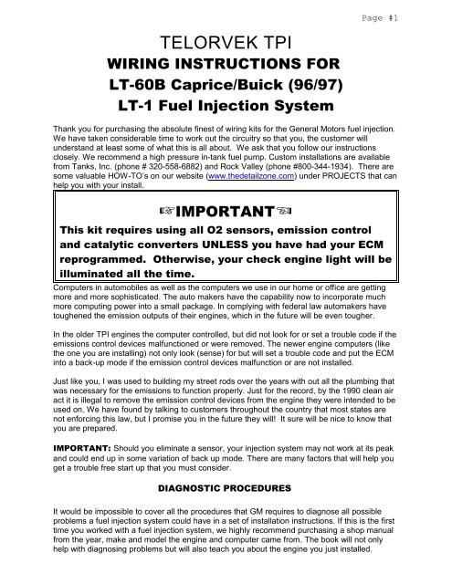
Page #1<br />
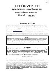
TELORVEK TPI<br />
WIRING INSTRUCTIONS FOR<br />
LT-60B Caprice/Buick (96/97)<br />
LT-1 Fuel Injection System<br />
Thank you for purchasing the absolute finest of wiring kits for the General Motors fuel injection.<br />
We have taken considerable time to work out the circuitry so that you, the customer will<br />
understand at least some of what this is all about. We ask that you follow our <strong>instructions</strong><br />
closely. We recommend a high pressure in-tank fuel pump. Custom <strong>installation</strong>s are available<br />
from Tanks, Inc. (phone # 320-558-6882) and Rock Valley (phone #800-344-1934). There are<br />
some valuable HOW-TO’s on our website (www.thedetailzone.com) under PROJECTS that can<br />
help you with your install.<br />
IMPORTANT<br />
This kit requires using all O2 sensors, emission control<br />
and catalytic converters UNLESS you have had your ECM<br />
reprogrammed. Otherwise, your check engine light will be<br />
illuminated all the time.<br />
Computers in automobiles as well as the computers we use in our home or office are getting<br />
more and more sophisticated. The auto makers have the capability now to incorporate much<br />
more computing power into a small package. In complying with federal law automakers have<br />
toughened the emission outputs of their engines, which in the future will be even tougher.<br />
In the older TPI engines the computer controlled, but did not look for or set a trouble code if the<br />
emissions control devices malfunctioned or were removed. The newer engine computers (like<br />
the one you are installing) not only look (sense) for but will set a trouble code and put the ECM<br />
into a back-up mode if the emission control devices malfunction or are not installed.<br />
Just like you, I was used to building my street rods over the years with out all the plumbing that<br />
was necessary for the emissions to function properly. Just for the record, by the 1990 clean air<br />
act it is illegal to remove the emission control devices from the engine they were intended to be<br />
used on. We have found by talking to customers throughout the country that most states are<br />
not enforcing this law, but I promise you in the future they will! It sure will be nice to know that<br />
you are prepared.<br />
IMPORTANT: Should you eliminate a sensor, your injection system may not work at its peak<br />
and could end up in some variation of back up mode. There are many factors that will help you<br />
get a trouble free start up that you must consider.<br />
DIAGNOSTIC PROCEDURES<br />
It would be impossible to cover all the procedures that GM requires to diagnose all possible<br />
problems a fuel injection system could have in a set of <strong>installation</strong> <strong>instructions</strong>. If this is the first<br />
time you worked with a fuel injection system, we highly recommend purchasing a shop manual<br />
from the year, make and model the engine and computer came from. The book will not only<br />
help with diagnosing problems but will also teach you about the engine you just installed.
Page #2<br />
WARNING!<br />
After the kit <strong>installation</strong> is complete and it is necessary to diagnose a<br />
starting or drive ability problem, follow the procedures recommended in<br />
the shop manual. All voltage tests must be preformed using a HIGH<br />
impedance, digital voltmeter. DO NOT use a test light on this system!<br />
DAMAGE WILL BE DONE to the engine computer if a test light is used on<br />
this system.<br />
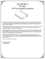
ENGINE CONTROL COMPUTER (ECM) "NEW" (GM PART #16214399) In 1994 the<br />
prom (mem-cal) is now part of the ECM and can not be removed. GM now programs the ECM<br />
for the vehicle it is being used in. In the past you were able to purchase the ECM and then<br />
purchase a prom (mem-cal) to install in the computer which tells the ECM the type of vehicle,<br />
engine size, transmission etc. After purchasing the ECM it MUST BE programmed for the<br />
engine it is being used on. It will be necessary to provide the dealership with a "VIN" number<br />
from a similar in order for them to program the computer.<br />
ELECTRONIC SPARK CONTROL MODULE (Knock Sensor Module) The ECM<br />
requires this module (GM PART LT-1 #16214671, 4.3 L99 #16214691) to be installed in the<br />
computer to function properly. NOTE: A new ECM WILL NOT function WITHOUT<br />
first being programmed and having a knock sensor module installed.<br />
ENGINE CONTROL COMPUTER (ECM) "USED" If you purchased the engine and<br />
computer used it must be used in a application as it was in the vehicle it was removed from.<br />
You will need all stock parts and sensors. The back page of the <strong>instructions</strong> is a list of optional<br />
accessories we offer and some of the General Motors part numbers you may need.
Page #3<br />
The Detail Zone fuel injection wire harnesses are “ALL” designed to follow<br />
the electronic circuitry of the vehicle your engine was removed from!<br />
Following this simple procedure allows our fuel injection harness customers<br />
to have their vehicles diagnosed by “ANY” GM dealer or reputable repair<br />
facility familiar with diagnosing fuel injection electronic systems.<br />
The Detail Zone does not re-engineer electronic circuitry that a vehicle<br />
manufacturer has spent millions of dollars on testing and designing. Our<br />
goal is to allow an “easy”, “neat”, “pain free” <strong>installation</strong> through quality<br />
<strong>installation</strong> <strong>instructions</strong> and a state of the art wiring kit.<br />
If your vehicle experiences starting or runability problems, 99% of the time<br />
it is some sort of mechanical, NOT A WIRING PROBLEM. Fuel injection<br />
engines still run similar to carbureted engines, the difference being that the<br />
engine computer receives “inputs” from various sensors throughout the<br />
engine. The computer then uses this information to calibrate fuel delivery<br />
and engine timing.<br />
Diagnosing a NO SPARK situation is the same on a computer controlled fuel<br />
injection engine as it is on a carbureted engine. Spark control, even though<br />
it may be done slightly different depending on engine year and make, is still<br />
essentially the same. A rotor is turned allowing spark to be provided to the<br />
plugs, the same as in a carbureted engine.<br />
Thank you for purchasing our <strong>product</strong>s!
Page #4<br />
STARTING INSTALLATION<br />
Since there are so many individual circuits to complete, we recommend that you connect them<br />
in the order that we prescribe. Disconnect the battery before starting and do not reconnect until<br />
instructed.<br />
TELORVEK PANEL LOCATION: (BEFORE DRILLING ANY HOLES) The location of<br />
the TELORVEK panel and engine control computer (ECM) can be any where you choose<br />
INSIDE the vehicle. They should be mounted in an accessible location, under the dash, under<br />
the seat or in the trunk are good. A lot of wires will be connected to the panel so the more<br />
accessible the panel the easier the wire connections will go. After the Telorvek panel <strong>installation</strong><br />
is complete, only the fuses need to be readily available.<br />
If mounting the panel under the dash or seat, leave enough extra wire so it can be pulled down<br />
from under the dash or from under the seat after all the connections are made. The reason for<br />
this, the panel can be used as a BREAKOUT BOX for diagnosing (trouble shooting)<br />
problems in the future. Some diagnostic procedures require taking volt readings on wires to find<br />
a problem. It is a lot easier to sit in a seat then bending over a fender.<br />
IMPORTANT: Check to be sure you have all the bags required for the <strong>installation</strong>. Each bag<br />
contains at least one sensor connection and approximately 20 feet of wire to reach the<br />
TELORVEK panel. We suggest opening bag #20 (mass air flow sensor) first. Plug the<br />
connector into the sensor and run the wires back to the TELORVEK panel. If they reach, then<br />
all the other sensor connections will also, because the MAF sensor is always mounted in front<br />
of the engine.<br />
We have packaged three sizes of terminal forks. The red terminals are for the 18 gauge wires<br />
and the blue are for 16-14 gauge wires and yellow are for 10-12 gauge wires. Use the red forks<br />
when installing terminals on the wires unless other wise directed.<br />
Always put the first terminal under a screw with the fat wire side down as in the<br />
drawing. Install any second terminals just the opposite as this will allow the screw<br />
to hold squarely and tight. The insulation from one terminal should not interfere<br />
with the one next to it.<br />
Use a crimping tool that is designed for insulated terminals. If the tool punctures the insulation<br />
(plastic) or damages it in any way, you are using the wrong tool. The proper tool will only<br />
"flatten" the plastic and if the handles are squeezed completely, the proper crimp has been<br />
made. Get in the habit of test pulling at each terminal as you crimp it to the wire.<br />
Any sensor that is difficult to hook-up should not be eliminated. All sensors are important if you<br />
desire your conversion to run as good as a factory engine. Eliminating any part of this kit WILL<br />
cause some portion of the EFI to work improperly.<br />
The Detail Zone has made every effort to assure a quality <strong>product</strong> and can<br />
assure you that this system works well in your application. Once you have<br />
confirmed proper <strong>installation</strong>, any trouble you experience will be a defective<br />
part or seat of the pants repair. Your unit can be tested at any General<br />
Motors Dealership with no difficulty.
Page #5<br />
Numbered terminal block cover strip reference.<br />
The drawing below is for your reference on the correct positioning of the Telorvek fuel injection<br />
panel terminal block cover strips.<br />
When connecting wires to the panel be sure the numbered terminals match the drawing below.<br />
Bag #20 MASS AIR FLOW SENSOR (MAF): On a factory <strong>installation</strong>, this sensor is<br />
mounted in the intake air duct between the air cleaner and plenum. Plug the three gang black<br />
connector into the sensor and run the wires back to the panel. Connect the yellow MAF A->6 to<br />
#6 , black MAF B->26 to #26 and the orange wire MAF C->4 to #4.<br />
BAG #21 INTAKE AIR TEMPERATURE SENSOR (IAT): Install this sensor in the duct<br />
work between the Air Cleaner and the Plenum. Plug the gray connector in to the sensor and<br />
run the wires back to the panel. Connect the black wire IAT A->7 to #7 and the tan wire IAT B-<br />
>8 to #8.<br />
Bag #22 MAP SENSOR: After installing the MAP (Manifold Air Pressure) sensor on top of<br />
the plenum in the holes provided by GM make sure that the nipple from the sensor is sealed<br />
were it goes through the plenum. Plug the green connector into the sensor and run the wires<br />
back to the panel. Connect the black wire MAP A->7 to #7, lt green wire MAP B->9 to #9 and<br />
the gray wire MAP C->10 to #10.<br />
Bag #23 ENGINE COOLANT TEMPERATURE SENSOR: The sensor is located off to<br />
one side of the water pump. Plug the connector into the sensor and run the wires back to the<br />
panel. Connect the black wire ECT A->12 to #12 and the yellow wire ECT B->11 to #11.<br />
Bag #24 THROTTLE POSITION SENSOR (TPS): The TPS sensor is located on the<br />
right side of the throttle body. Plug the connector into the sensor and run the wires back to the<br />
panel. Connect the gray wire TPS A->14 to #14, black wire TPS B->12 to #12 and the dk blue<br />
wire TPS C->13 to #13.<br />
Bag #25 ELECTRONIC SPARK TIMING (Distributor): The LT-1 engine is normally<br />
supplied with an assembly/diagnostic test connection harness (about 2 feet long) running from<br />
the distributor to the middle of the right valve cover. Our harness is equipped with this<br />
connector. If you have the factory GM harness in place, discard our short assembly/diagnostic<br />
harness and plug directly into the GM harness.
Page #6<br />
IMPORTANT: Over the history of the LT-1 engine two different distributor<br />
connectors were used, one short (supplied in the kit) and one long (2 1/8<br />
inch long not available to aftermarket). If you are not reusing the factory<br />
assembly/diagnostic harness, check the hole depth of the distributor<br />
connection and compare it to the harness supplied in the kit. DO NOT<br />
JUST PLUG IT IN! Both the short and long connectors are the same<br />
diameter. If you plug the short connector into the distributor that requires<br />
the long connector, the connection seems secure however the contacts in<br />
the distributor have not made contact with the terminals in the connector.<br />
This prevents the engine from starting. The long connector distributor<br />
harness is available through GM under part number 12130319.<br />
After making the distributor connection run the wires to the panel. Connect the black wire DIST<br />
A->15 to #15, the purple wire DIST B->16 to #16, the red wire DIST C->17 to #17 and the pink<br />
wire DIST D->18 to #18.<br />
Bag #26A IGNITION COIL & IGNITION COIL MODULE: The ignition coil is located on<br />
the front of the engine. Plug in the three gang connector with the orange and green wires into<br />
the coil and run the orange wire back to the panel. Connect the orange IGN COIL A->5 to #5<br />
using a yellow terminal. Also supplied is a wire for a tach. Connect the purple wire 95->TACH<br />
to terminal #95 and run it to the tach.<br />
The ignition coil module is located on the front of the engine right next to the coil. Plug in the<br />
four gang connector and run the wires back to the panel. Connect the white wire COIL DR B-<br />
>19 to #19, orange COIL DR A->5 to #5 and the black wire COIL DR C->25 to #25.<br />
Bag #26C CRANK SHAFT POSITION SENSOR: Plug in the connector into the sensor<br />
located by the lower crank pulley and run the wires back to the panel. Connect the yellow wire<br />
CRK SHAFT C->30 to #30, orange CRK SHAFT A->1 to #1 and pink CRK SHAFT B->18 to<br />
#18.<br />
Bag #27 IDLE AIR CONTROL (IAC): The IAC is located on the right side of the throttle body.<br />
Plug the four gang connector into the IAC and run the wires back to the panel.<br />
NOTE <br />
This connector has two light blue and two light green wires. READ the<br />
printing on the wires carefully making sure the wires are being connected<br />
to the correct terminals.<br />
Connect the wires to the panel as follows: lt green IAC A->20 to #20, lt green IAC B->21 to #21,<br />
lt blue IAC C->22 to #22 and lt blue IAC D->23 to #23.
Page #7<br />
Bag #28 INJECTORS: In 1994 GM has started to fire the injectors sequentially (one at a<br />
time) unlike in the past when the injectors where fired one bank (four) at a time. According to<br />
GM this did not improve horse power but was done for better emissions at low RPM'S. The<br />
injector wiring is in two sections, one for the left side injectors and one for the right side<br />
injectors. Note the color of wires running from the injector connectors. The left injector harness<br />
has pink, black, purple, white, red wires and the right injector harness has pink, lt green, lt blue,<br />
yellow and dk blue wires. Follow the paragraphs below on their connections:<br />
LEFT INJECTOR CONNECTIONS: Starting from the front of the engine and working<br />
towards the fire wall, plug the injectors in as follows: injector #1 has pink & black, injector #3<br />
has pink & purple, injector #5 has pink & white and injector #7 has pink & red wires.<br />
RIGHT INJECTOR CONNECTIONS: Starting from the front of the engine and working<br />
towards the fire wall, plug the injectors in as follows: injector #2 has pink & lt green, injector #4<br />
has pink & lt blue, injector #6 has pink & yellow and injector #8 has pink & dk blue.<br />
After all the injectors are plugged in run all the wires back to the TELORVEK panel. Note the<br />
injector harness has two pink wires. READ the printing on the wires<br />
carefully before connecting them. Using the blue terminals, connect the pink wire INJ<br />
1->41 to #41 and the other pink wire INJ 2->46 to #46. Using the red terminals, connect the<br />
rest of the injector harness wires as follows: black INJ 1->42 to #42, purple INJ 3->43 to #43,<br />
white INJ 5->44 to #44, red INJ 7->45 to #45, lt green INJ 2->47 to #47, lt blue INJ 4->48 to<br />
#48, yellow INJ 6->49 to #49 and dk blue INJ 8->50 to #50.<br />
Bag #29A OXYGEN SENSOR (4): GM now uses heated O2 sensors. These sensors help<br />
the ECM go into closed loop faster. This area of the vehicle is hot so keep the wires away from<br />
the exhaust. Four sensors are required per engine. Install the left and right front O2<br />
sensors in each exhaust manifold or in the header collector as close to the<br />
block as possible. The left and right rear O2 sensors mount behind the<br />
catalytic converters in each exhaust pipe. These sensors monitor the status of the<br />
converters and WILL set a trouble code if a faulty converter is detected or a converter is not<br />
used at all. NOTE: The O2 sensors do not send a signal to the ECM until they reach 600<br />
degrees. Mounting them in header collectors may take longer for them to heat up causing the<br />
ECM to stay in OPEN LOOP longer than normal. If you must install an adapter, use The Detail<br />
Zone part # OS-30.<br />
LEFT FRONT O2: The four gang connector with the orange, black, tan and lt blue wires<br />
running from it plugs into the left front oxygen sensor.<br />
RIGHT FRONT O2: The other four gang connector with the orange, black, tan and purple<br />
wires running from it plugs into the right front oxygen sensor.<br />
LEFT REAR O2: The four gang connector with the orange, black, dk green and lt green wires<br />
running from it plugs into the left rear oxygen sensor.
Page #8<br />
RIGHT REAR O2: The other four gang connector with the orange, black, brown and yellow<br />
wires running from it plugs into the right rear oxygen sensor.<br />
Run all the wires back to the panel and connect the black wires LF O2 C->24, and the RT O2<br />
C->24 to #24. Connect the other two black wires RT REAR O2 C->29 and the LF REAR O2 C-<br />
>29 to #29. Connect the tan LF O2 A->51 to #51, the other tan RT O2 A->53 to #53, lt blue LF<br />
O2 B->52 to #52, purple RT O2 B->54 to #54, yellow RT REAR O2 A->91 to #91, brown RT<br />
REAR O2 B->92 to #92, dk green LF REAR O2 A->93 to #93 and the lt green LF REAR O2 B-<br />
>94 to #94. Using the blue terminals connect the two orange wires LF O2 D->3 and RT O2 D-<br />
>3 to #3 and the other two orange wires RT REAR O2 D->31 and LF REAR O2 D->31 to #31.<br />
Bag #30B KNOCK SENSOR WIRING (2): There are two knock sensors located on each<br />
side of the engine block screwed into the block drain holes. These sensors will inform the<br />
computer of detonation and readjust the timing accordingly. The knock sensor must be used<br />
because it advances and retards the timing. Plug the connector with the lt blue plugs into the<br />
left knock sensor and the connector with the dk blue wire plugs into the right knock sensor.<br />
Run the wires to the panel and connect the lt blue to #58 and the dk blue to #55.<br />
Transmission <strong>Wiring</strong><br />
The 4L60-E automatic transmission is a computer controlled, electronic shift transmission. In<br />
order to follow the GM color codes some of the wire colors have been duplicated. Look at the<br />
printing on the wire carefully before connecting the wires to the panel.<br />
4L60-E Automatic Transmission <strong>Wiring</strong><br />
(<strong>Wiring</strong> Bags #31 & #32C)<br />
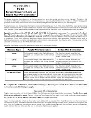
Bag #31 BRAKE SIGNAL (TCC CUT OUT RELAY): In order for the transmission<br />
and torque converter clutch to operate properly a signal must be sent to the ECM to tell it<br />
when the brakes are applied. Mount the relay within thirty inches of the TELORVEK panel.<br />
Run the orange wire TCC CUT OUT->36 to #36, lt blue wire TCC CUT OUT->37 to #37 and<br />
the black wire TCC CUT OUT->28 to #28. The long single purple TCC REL->BRK SW runs<br />
to the cold side of the brake switch (hot only when the brakes are applied).<br />
Bag #32C AUTOMATIC 4L60-E TRANSMISSION: Un-coil the large harness and<br />
plug the connector into the transmission. Run the wires to the TELORVEK panel.<br />
NOTE <br />
Due to the amount of wires necessary to operate the 4L60-E<br />
transmission and to follow GM color codes, some wire colors<br />
had to be duplicated. READ the printing on the wires<br />
carefully before connecting them to the TELORVEK panel.<br />
Connect the wires to the TELORVEK panel as follows: lt green TRANS A->65 to #65, yellow<br />
TRANS B->66 to #66, red TRANS C->67 to #67, lt blue TRANS D->68 to #68, orange<br />
TRANS E->34 to #34, yellow TRANS L->69 to #69, black TRANS M->70 to #70, pink<br />
TRANS N->71 to #71, red TRANS P->72 to #72, dk blue TRANS R->73 to #73, white<br />
TRANS S->74 to #74, lt green TRANS U->84 to #84 and the tan TRANS T->75 to #75.
Page #9<br />
Bag #33 SPEED SENSOR: A VSS signal input is needed on all General Motors TPI<br />
engines. If the ECM does not see that input a CODE WILL SET. The VSS input helps control<br />
transmission shifts, some of the EGR and IAC functions. Plug the connector into the sensor<br />
and run the wires to the TELORVEK panel. Connect the purple VSS A->76 to #76 and VSS B-<br />
>77 to #77.<br />
ELECTRIC SPEEDOMETER CONNECTION: Terminal #78 on the Telorvek panel is for<br />
the dash mounted electric speedometer. This terminal will generate 4000 pulses per mile.<br />
Wire and calibrate the speedometer following the <strong>instructions</strong> that came with your<br />
speedometer.<br />
Bag #34 FUEL PUMP: The fuel pump relay is located in the cover of the TELORVEK panel and<br />
is pre-wired. A relay must be installed in the connector (GM part #14100455) or the pump WILL<br />
NOT operate. Connect the tan 56->FUEL PUMP wire to #56 on the panel and run it to the fuel<br />
pump. The tan wire then connects to the positive terminal on the pump and the black FUEL<br />
PUMP GRND wire connects to the negative side of the pump and then to a good ground. A<br />
pump that is capable of producing a minimum of 45 PSI must be used.<br />
Bag #35 PRIMARY & SECONDARY FAN RELAYS: Allowing the engine computer to<br />
control these fans works far better than any other control such as wired direct or with a toggle<br />
switch. Let the computer control the engine temperature as it should for best performance.<br />
NOTE: DO NOT LOWER THE THERMOSTAT TEMPERATURE, DOING SO WILL<br />
CAUSE THE ENGINE TO RUN RICH.<br />
The primary and secondary fan relays are located in the cover of the TELORVEK panel and are<br />
pre-wired. Connect the lt blue 79->PRIME RAD FAN to #79 and the purple 80->2ND RAD FAN<br />
to #80 and run both wires to the fans. Connect the lt blue wire to the primary fan and the purple<br />
to the secondary fan. Both fans must be grounded.<br />
WARNING!!<br />
Don't forget to install the primary and secondary relays in the connectors<br />
located in the cover of the TELORVEK panel. The fans WILL NOT operate<br />
unless the relays are installed. Use GM part #14100455 in both<br />
connectors.<br />
Bag #36 PARK/NEUTRAL RELAY: This system was developed to allow a regular park /<br />
neutral switch tell the computer when the vehicle is in park, neutral or drive. Since the signals<br />
are different from normal neutral switches, we have made this small circuit that will plug into a<br />
stock GM neutral switch or splice to just about any two wire neutral switch. The signal input<br />
controls the idle air control (IAC), vehicle speed sensor diagnostics (VSS) and exhaust gas<br />
recirculating: (EGR).<br />
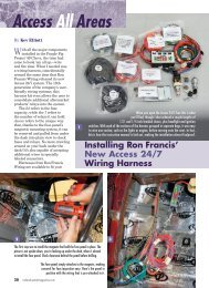
If you are using <strong>Ron</strong> <strong>Francis</strong> Wire Works <strong>Wiring</strong> kit, this is a simple, color coded plug-in to GM<br />
Neutral Safety Switches. The regular car wiring that normally runs to the neutral safety now<br />
plugs into the P/N relay kit with the blue and purple wires in the black connector. The plug with<br />
the blue and black wires running from the relay is connected to the original neutral safety<br />
switch. Run the black wire with the ring terminal to a good ground. The orange wire PN RELAY-<br />
>81 is run to the TELORVEK panel and connects to #81.
Page #10<br />
NOTE: Using any other standard neutral switch requires removing the plug and splicing. Either<br />
color wire can be used on either terminal. The black plug with the Lt Blue and Black wires is<br />
connected into your neutral safety switch. If the connector on the wires doesn't fit your<br />
application, remove it and connect the wires to the neutral safety switch directly.<br />
<br />
<br />
The blue wire in the plug must be connected to the 12 volt supply from the ignition<br />
switch. This wire becomes hot (12 Volts) when you turn the key to crank.<br />
The purple wire is connected to the wire that runs to the starter solenoid.<br />
Run the orange wire to the TELORVEK panel and connect it to #81.<br />
Don't forget to install a relay (GM part #14100455).<br />
Bag #37C SERVICE ENGINE SOON LIGHT (S.E.S) and DATA LINK<br />
CONNECTOR. (DLC): The DLC is the diagnostic link for computerized testing at your local<br />
GM dealer or a hand held scanner. Please consider a very accessible location for this important<br />
part. Mount the connector in the desired location and run the wires back to the panel. Connect<br />
the black wire DLC 4->27 to #27, the white wire DLC 11->115 to #115, the purple DLC 2->110<br />
to #110, the red DLC 16->38 to #38 and the tan wire DLC 9->99 to #99.<br />
The S.E.S light can be any two wire un-grounded 12 volt lamp located on the dash board or<br />
where ever desired. Connect the pink 35->SES LT to #35 and the brown 40->SES LT to #40.<br />
Run the wires to the SES LT and make the connection. Connecting a S.E.S light on the dash is<br />
not necessary, the yellow L.E.D light on top of the TELORVEK panel performs the same<br />
function.<br />
Bag #38A EMISSION BAG: The EGR solenoid is mounted on the left side of the manifold<br />
and the Canister Purge solenoid and Evaporative Emissions Vacuum Switch is on the right side<br />
of the manifold. If you desire a clean look on the manifold, relocate these items and mount<br />
them under the dash. They must be plugged in or trouble codes will set.<br />
EXHAUST GAS RECIRCULATION: The black connector with pink and gray wires is for<br />
the EGR solenoid. Plug in the connector to the EGR solenoid and run the wires to the panel.<br />
Connect the pink wire EGR SOL A->2 to #2 and the gray wire EGR B->101 to #101<br />
CANISTER PURGE SOLENOID: Plug the red connector with the pink and dk green wires<br />
into the canister purge solenoid and run the wires to the panel. Connect the pink wire PURGE<br />
SOL A->2 to #2 and the dk green PURGE SOL B->102 TO #102.<br />
EVAPORATIVE EMISSIONS VACUUM SWITCH: Plug in the connector and run the<br />
wires back to the panel. Connect the pink wire EVAP SW B->114 to #114 and the black EVAP<br />
SW A->28 to #28.<br />
AIR PUMP/SECONDARY AIR INJECTION BLEED VALVE SWITCH: The air pump is<br />
controlled by the ECM through a relay located in the cover of the TELORVEK panel. A relay<br />
(GM part #14100455 must be installed in the connector or a trouble code will set. The three<br />
gang connector plugs into the air pump. The two gang connector plugs into the bleed valve<br />
switch. Ground the black wire running from the air pump connector and the bleed valve switch.<br />
Using the blue terminal connect the red wire AIR PUMP A->57 to #57 on the TELORVEK panel.
Page #11<br />
Bag #39: Contained in this bag is the wiring for the engine oil level (EOL) sensor, low oil<br />
indicator light, torque converter temperature (TCC TEMP) sensor, power steering pressure<br />
switch (PS SW) and the engine oil change indicator light (OIL CHNG LT). Wire in these items<br />
as designated below.<br />
LOW OIL & ENGINE OIL CHANGE INDICATOR LIGHTS: Two un-grounded, two wire<br />
lights are required for these connections. Connect the pink wires (32->LOW OIL LT) & (32-<br />
>OIL CHANGE LT) to #32 on the panel and run them to the indicator lights. Connect the pink<br />
low oil light wire to one of the wires running from the low oil indicator light and the other pink oil<br />
change light wire to one of the wires running from the oil change indicator light. Connect the<br />
brown wire (109->LOW OIL LT) to #109 and connect it to the other wire running from the low oil<br />
indicator light. Connect the gray wire (106->CHNG OIL LT) to #106 on the panel and connect it<br />
to the other wire running from the change oil light.<br />
ENGINE OIL LEVEL SENSOR (EOL): The EOL sensor is located in the oil pan. Plug in<br />
the connector and ground the black wire (EOL A->GRND) to a good ground. Run the brown<br />
wire (EOL B->105) to #105.<br />
POWER STEERING SWITCH (PS SW): The PS SW is located in the power steering line.<br />
This switch senses when the pressure gets high (such as when the vehicle is in a parking<br />
maneuver) and raises the idle speed to compensate for the additional load. Plug the connector<br />
into the sensor and ground the black wire (PS SW B->GRND) to a good ground. Connect the<br />
orange wire (PS SW A->104) to #104 on the panel.<br />
TRANSMISSION FLUID TEMPERATURE SENSOR (TCC TEMP): The ECM uses the<br />
TCC TEMP to determine torque converter apply and release schedules and shift quality. Plug<br />
the connector into the sensor and ground the black wire (TCC TEMP B->GRND) to a good<br />
ground. Connect the white wire (TCC TEMP A->103) to #103 on the panel.<br />
OTHER HARNESS CONNECTIONS<br />
A/C REQUEST: Terminal #82<br />
A/C STATUS CONNECTION: Terminal #83<br />
A/C EVAPORATOR TEMPERATURE: Terminal #87<br />
A/C Relay clutch Control: Terminal #107<br />
A/C Pressure Signal: Terminal #108
Page #12<br />
FINISHING UP<br />
The ECM accepts four connectors. The TELORVEK panel has four ECM connectors running<br />
from it with different color plugs. Stamped in the case of the ECM next to the four harness<br />
connections is the color harness plug that plugs in to that slot. Plug the connectors into the<br />
computer making sure the connector locks snap into the computer case.<br />
Three connections remain, battery hot, ignition and battery ground. These three wires are<br />
running out of the TELORVEK panel along with the wires to the computer. Un-coil them and<br />
wire as follows:<br />
BATTERY CONNECTION: The red wire out of the plug connects to a battery (hot all the<br />
time) source. Run this wire to the positive battery post if the TELORVEK panel and battery are<br />
mounted in the rear of the vehicle or to the starter solenoid if the panel is mounted towards the<br />
front of the vehicle. If your vehicle is equipped with a master disconnect, connect this wire to the<br />
hot side of the switch.<br />
IGNITION CONNECTION: The orange wire is connected to a keyed ignition source (hot<br />
with the key in run and crank).<br />
NOTE: After you wired in the ignition connection, check it with a test light,<br />
make sure this wire remains hot with the key in the run position and crank<br />
position.<br />
BATTERY GROUND: The Black ground wire from the plug runs direct to the battery. Do not<br />
consider grounding the battery to the frame and then the engine to the frame. Run the battery<br />
ground directly to the engine.<br />
You have now completed the kit <strong>installation</strong>. You may have noted empty terminals on the<br />
Telorvek panel that do not have any wire connections to them. The Detail Zone runs all<br />
computer connections out of the computer plug(s) even if they are not used in aftermarket<br />
applications.<br />
STARTING THE ENGINE<br />
You have now made all of the connections necessary to TRY to start your car. If you try now,<br />
you will be disappointed since you did not hook up the battery. You can do so now. If you turn<br />
the key on but do not crank engine, you will hear the fuel pump for about 2 to 4 seconds before<br />
it stops. This will indicate the pump is ready. During normal operating it is best if you do not<br />
wait until the pump stops as this is not an indication that the pressure is up. There is no need to<br />
"pump" the throttle to start a fuel injected car.<br />
CRITICAL! After the motor is running check the MAP sensor to make sure<br />
there is not any vacuum leaks!
Page #13<br />
Telorvek Panel Fuse Designation, Size and Relay Center Layout<br />
Fuse Designation & Size<br />
The harness has a total of eight fuses. Shown below is a diagram of what each fuse protects.<br />
Top, Front View Of Fuse Blocks<br />
Ignition Feed<br />
Fuse Row #1<br />
Battery Feed<br />
Fuse Row #2<br />
Fuse<br />
Designation<br />
Fuse Size<br />
Block #1<br />
Fuse<br />
Designation<br />
Size<br />
Fuse<br />
Block #2<br />
MAF,O2 LF & RT EGR, C/P<br />
VSS<br />
15 AMP FUEL PUMP RELAY,<br />
ECM<br />
15 AMP<br />
S.E.S LT, PRIMARY & SECONDARY FAN<br />
RELAY, TCC CUT OUT RELAY,<br />
4L60-E TRANSMISSION<br />
INJECTORS<br />
1,3,5,7<br />
INJECTORS<br />
2,4,6,8<br />
15 AMP PRIMARY FAN RELAY 30 AMP<br />
10 AMP SECONDARY FAN RELAY 30 AMP<br />
10 AMP AIR PUMP 20 AMP<br />
FUEL PUMP<br />
RELAY<br />
PRIMARY FAN<br />
RELAY<br />
SECONDARY FAN<br />
RELAY<br />
AIR PUMP<br />
RELAY<br />
RELAY CENTER: In the cover of the TELORVEK panel are four relays the ECM uses to control<br />
fuel pump, primary & secondary cooling fans and the air pump. The ECM can not handle heavy<br />
load items and it requires a relay to handle the load and the ECM then controls the relay. The<br />
harness has a total of six relays, four in the cover of the TELORVEK panel and two that are<br />
mounted remotely. All relays in the harness require GM part # 14100455.<br />
WARNING: All relays must be installed in the connectors. Eliminating any<br />
of them will cause damage to the engine.
Page #14<br />
TROUBLE CODE DEFINITION<br />
The ECM looks for certain parameters from each sensor it controls. If it sees one out of<br />
specification it will set and store a trouble code. Not all codes will light the service engine soon<br />
light. There is two types of trouble codes:<br />
HARD CODE: A hard code will light the S.E.S light and in most cases (not all) put the ECM<br />
into a back-up (open loop) mode. When this happens the timing remains fixed (will not advance<br />
or retard), both cooling fans will turn on and the engine will run only taking the input from the<br />
TPS sensor. This usually causes a rich condition as well.<br />
SOFT CODE: A soft code will not light the S.E.S light. This type of code will set, store and<br />
can only be read by connecting a scanner to the DLC connector. This type of code WILL NOT<br />
put the computer into a back-up mode or cause any running problems.<br />
NOTE: In order to read any trouble codes it will be necessary to connect a scan tool to the<br />
DLC connector. This service can be performed at any GM dealer or repair facility in your area.<br />
You can not put 1996 and newer engines in diagnostic mode by jumping wires together in the<br />
DLC connector like could be done in the past, a scan tool must be used.
Page #15<br />
LT-1 TROUBLE CODES<br />
PO100 MAF Insufficient Signal Activity<br />
PO101 MAF System Performance<br />
PO102 MAF Circuit Low Frequency<br />
PO103 MAF Circuit High Frequency<br />
PO106 MAP System Performance<br />
PO107 MAP Circuit Low Performance<br />
PO108 MAP Circuit High Performance<br />
PO112 IAT Circuit Low Voltage<br />
PO113 IAT Circuit High Voltage<br />
PO117 ECT Circuit Low Voltage<br />
PO118 ECT Circuit High Voltage<br />
PO121 TPS Insufficient Signal Activity<br />
PO122 TPS Circuit Low Voltage<br />
PO123 TPS Circuit High Voltage<br />
PO125 ECT Excessive Time to Closed Loop<br />
PO131 O2 LF FRT Low Voltage<br />
PO132 O2 LF FRT High Voltage<br />
PO133 O2 LF FRT Slow Response<br />
PO134 O2 LF FRT Insufficient Signal Activity<br />
PO135 O2 LF FRT Heater Circuit<br />
PO137 O2 LF REAR Low Voltage<br />
PO138 O2 LF REAR High Voltage<br />
PO140 O2 LF REAR Insufficient Signal Activity<br />
PO141 O2 LF REAR Heater Circuit<br />
PO151 O2 RT FRT Low Voltage<br />
PO152 O2 RT FRT High Voltage<br />
PO153 O2 LF FRT Slow Response<br />
PO154 O2 LF FRT Insufficient Signal Activity<br />
PO155 O2 LF FRT Heater Circuit<br />
PO157 O2 RT REAR Low Voltage<br />
PO158 O2 LF REAR High Voltage<br />
PO160 O2 LF REAR Insufficient Signal Activity<br />
PO161 O2 LF REAR Heater Circuit<br />
PO171 Left Fuel Trim System Lean<br />
PO172 Left Fuel Trim System Rich<br />
PO174 Right Fuel Trim System Lean<br />
PO175 Right Fuel Trim System Rich<br />
PO200 Injector Control Circuit<br />
PO300 Engine Misfire Detected<br />
PO323 Distributor Low Circuit Intermittent<br />
PO325 Knock Sensor Module<br />
PO332 Knock Sensor Circuit Low/High Voltage<br />
PO335 Crankshaft Position Circuit<br />
PO336 Crankshaft Position Circuit Performance<br />
PO372 Distributor High Circuit<br />
PO400 EGR System<br />
PO403 EGR Solenoid Control Circuit<br />
PO410 Secondary Air Injection System<br />
PO412 Secondary Air Injection System Control<br />
Circuit<br />
PO420 Left Catalytic Converter System<br />
PO430 Right Catalytic Converter System<br />
PO441 EVAP No Flow During Purge<br />
PO443 EVAP Purge Control Circuit<br />
PO500 VSS Circuit (Manual Transmission Only)<br />
PO502 VSS Circuit Low Input<br />
PO506 ISC Low Valve Responding<br />
PO507 ISC High Valve Responding<br />
PO530 A/C Refrigerant Pressure<br />
PO531 A/C Refrigerant Pressure Circuit Performance<br />
PO560 System Voltage Malfunction<br />
PO562 System Voltage Low<br />
PO563 System Voltage High<br />
PO601 PCM Memory<br />
PO602 PCM Not Programmed<br />
PO712 Transmission Fluid Temperature High<br />
PO713 Transmission Fluid Temperature Low<br />
PO719 TCC Brake Switch Circuit Low<br />
PO724 TCC Brake Switch Circuit High<br />
PO742 TCC Stuck On<br />
PO748 Pressure Control Solenoid<br />
PO751 1-2 Shift Performance Solenoid<br />
PO753 1-2 Shift Solenoid Electrical<br />
PO756 2-3 Shift Solenoid Performance<br />
PO758 2-3 Shift Solenoid Electrical<br />
P1107 MAP Circuit Intermittent Low Voltage<br />
P1111 IAT Circuit Intermittent High Voltage<br />
P1112 IAT Circuit Intermittent Low Voltage<br />
P1114 ECT Circuit Intermittent Low Voltage<br />
P1115 ECT Circuit Intermittent High Voltage<br />
P1121 TPS Circuit Intermittent High Voltage<br />
P1122 TPS Circuit Intermittent Low Voltage<br />
P1133 Left Front O2 Insufficient Switching<br />
P1134 Left Front Transition Time Ratio<br />
P1153 Right Front O2 Insufficient Switching<br />
P1154 Right Front O2 Transition Time Ratio<br />
P1171 Fuel System Lean During Acceleration<br />
P1222 Injector Control Circuit Intermittent<br />
P1351 Ignition Control Circuit High Voltage<br />
P1361 Ignition Control Circuit Low Voltage<br />
P1371 Distributor Ignition Low Resolution Circuit<br />
P1380 Rough Road Data Unusable<br />
P1381 Misfire Detected<br />
P1415 Secondary Air Injection Left Side<br />
P1416 Secondary Air Injection Right Side<br />
P1441 EVAP Flow During Non-Purge<br />
P1508 ISC System Low<br />
P1509 ISC System High<br />
P1532 A/C Evaporator Temp Circuit Low<br />
P1533 A/C Evaporator Temp Circuit High<br />
P1539 A/C Clutch Status Circuit High<br />
P1543 A/C System Performance<br />
P1545 A/C Clutch Relay Control Circuit<br />
P1546 A/C Clutch Status Control Circuit<br />
P1572 Traction Control System<br />
P1626 Theft Deterrent System<br />
P1641 Fan Relay One Control Circuit<br />
P1642 Fan Relay Two Control Circuit<br />
P1643 Engine Speed Output Circuit<br />
P1652 VSS Output Circuit<br />
P1657 Skip Shift System Control Circuit<br />
P1661 S.E.S Light Control Circuit<br />
P1667 Reverse Inhibit Solenoid Control Circuit<br />
P1810 Pressure Sw Assembly Circuit Malfunction<br />
P1812 Transmission Fluid Temp High<br />
P1860 TCC PWM Solenoid Circuit Electrical<br />
P1864 TCC Solenoid Circuit Electrical<br />
P1870 Transmission Component Slipping<br />
P1886 2-3 Control Solenoid Circuit Electrical
Page #16<br />
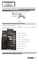
LT-1 Cooling Systems<br />
General Motors has Installed quite an elaborate recovery system to handle their new reverse<br />
cooling system. This system is in place to handle AIR POCKETS that may stop coolant flow<br />
through the entire motor. EXTRA care should be taken to bleed (burp) all the air out of the<br />
motor. There is a bleed valve on the thermostat housing for this purpose. Bleed this valve after<br />
the engine thermostat has opened. Repeat after some usage.<br />
Care should be taken to be sure the air bleed line from the back of the engine is correctly<br />
plumbed. If not done exactly like the Camaro, You may need an extra connection in the top of<br />
the radiator. Install a water temperature gauge and keep a close eye on it during testing and the<br />
first 500 miles.<br />
Optional Accessories<br />
GM Part # The Detail Zone Part #<br />
Electronic Control Module 16214399 EC-67<br />
Electronic Control Module (LT-1) 16214671<br />
(Knock Sensor Module)<br />
Electronic Control Module (L99) 16214691<br />
(Knock Sensor Module)<br />
Oxygen Sensor (heated) 2 req. 25312184 OS-55<br />
Fuel Pump Relay 14100455 RL-5<br />
Cooling Fan Relay (2) 14100455 RL-5<br />
Park Neutral Relay 14100455 RL-5<br />
Air Blower Relay 14100455 RL-5<br />
TCC Cut Out Relay 14100455 RL-5<br />
Copyright Infringement<br />
The Detail Zone has taken the extra effort to produce a quality, easy to<br />
understand <strong>instructions</strong>. We will aggressively prosecute any other harness<br />
supplier who attempts to copy this material!!<br />
Copyright 1992-1994 The Detail Zone