product installation instructions - Ron Francis Wiring
product installation instructions - Ron Francis Wiring
product installation instructions - Ron Francis Wiring

You also want an ePaper? Increase the reach of your titles
YUMPU automatically turns print PDFs into web optimized ePapers that Google loves.
Page #6<br />
IMPORTANT: Over the history of the LT-1 engine two different distributor<br />
connectors were used, one short (supplied in the kit) and one long (2 1/8<br />
inch long not available to aftermarket). If you are not reusing the factory<br />
assembly/diagnostic harness, check the hole depth of the distributor<br />
connection and compare it to the harness supplied in the kit. DO NOT<br />
JUST PLUG IT IN! Both the short and long connectors are the same<br />
diameter. If you plug the short connector into the distributor that requires<br />
the long connector, the connection seems secure however the contacts in<br />
the distributor have not made contact with the terminals in the connector.<br />
This prevents the engine from starting. The long connector distributor<br />
harness is available through GM under part number 12130319.<br />
After making the distributor connection run the wires to the panel. Connect the black wire DIST<br />
A->15 to #15, the purple wire DIST B->16 to #16, the red wire DIST C->17 to #17 and the pink<br />
wire DIST D->18 to #18.<br />
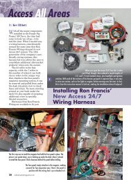
Bag #26A IGNITION COIL & IGNITION COIL MODULE: The ignition coil is located on<br />
the front of the engine. Plug in the three gang connector with the orange and green wires into<br />
the coil and run the orange wire back to the panel. Connect the orange IGN COIL A->5 to #5<br />
using a yellow terminal. Also supplied is a wire for a tach. Connect the purple wire 95->TACH<br />
to terminal #95 and run it to the tach.<br />
The ignition coil module is located on the front of the engine right next to the coil. Plug in the<br />
four gang connector and run the wires back to the panel. Connect the white wire COIL DR B-<br />
>19 to #19, orange COIL DR A->5 to #5 and the black wire COIL DR C->25 to #25.<br />
Bag #26C CRANK SHAFT POSITION SENSOR: Plug in the connector into the sensor<br />
located by the lower crank pulley and run the wires back to the panel. Connect the yellow wire<br />
CRK SHAFT C->30 to #30, orange CRK SHAFT A->1 to #1 and pink CRK SHAFT B->18 to<br />
#18.<br />
Bag #27 IDLE AIR CONTROL (IAC): The IAC is located on the right side of the throttle body.<br />
Plug the four gang connector into the IAC and run the wires back to the panel.<br />
NOTE <br />
This connector has two light blue and two light green wires. READ the<br />
printing on the wires carefully making sure the wires are being connected<br />
to the correct terminals.<br />
Connect the wires to the panel as follows: lt green IAC A->20 to #20, lt green IAC B->21 to #21,<br />
lt blue IAC C->22 to #22 and lt blue IAC D->23 to #23.