product installation instructions - Ron Francis Wiring
product installation instructions - Ron Francis Wiring
product installation instructions - Ron Francis Wiring

You also want an ePaper? Increase the reach of your titles
YUMPU automatically turns print PDFs into web optimized ePapers that Google loves.
Page #11<br />
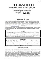
Bag #39: Contained in this bag is the wiring for the engine oil level (EOL) sensor, low oil<br />
indicator light, torque converter temperature (TCC TEMP) sensor, power steering pressure<br />
switch (PS SW) and the engine oil change indicator light (OIL CHNG LT). Wire in these items<br />
as designated below.<br />
LOW OIL & ENGINE OIL CHANGE INDICATOR LIGHTS: Two un-grounded, two wire<br />
lights are required for these connections. Connect the pink wires (32->LOW OIL LT) & (32-<br />
>OIL CHANGE LT) to #32 on the panel and run them to the indicator lights. Connect the pink<br />
low oil light wire to one of the wires running from the low oil indicator light and the other pink oil<br />
change light wire to one of the wires running from the oil change indicator light. Connect the<br />
brown wire (109->LOW OIL LT) to #109 and connect it to the other wire running from the low oil<br />
indicator light. Connect the gray wire (106->CHNG OIL LT) to #106 on the panel and connect it<br />
to the other wire running from the change oil light.<br />
ENGINE OIL LEVEL SENSOR (EOL): The EOL sensor is located in the oil pan. Plug in<br />
the connector and ground the black wire (EOL A->GRND) to a good ground. Run the brown<br />
wire (EOL B->105) to #105.<br />
POWER STEERING SWITCH (PS SW): The PS SW is located in the power steering line.<br />
This switch senses when the pressure gets high (such as when the vehicle is in a parking<br />
maneuver) and raises the idle speed to compensate for the additional load. Plug the connector<br />
into the sensor and ground the black wire (PS SW B->GRND) to a good ground. Connect the<br />
orange wire (PS SW A->104) to #104 on the panel.<br />
TRANSMISSION FLUID TEMPERATURE SENSOR (TCC TEMP): The ECM uses the<br />
TCC TEMP to determine torque converter apply and release schedules and shift quality. Plug<br />
the connector into the sensor and ground the black wire (TCC TEMP B->GRND) to a good<br />
ground. Connect the white wire (TCC TEMP A->103) to #103 on the panel.<br />
OTHER HARNESS CONNECTIONS<br />
A/C REQUEST: Terminal #82<br />
A/C STATUS CONNECTION: Terminal #83<br />
A/C EVAPORATOR TEMPERATURE: Terminal #87<br />
A/C Relay clutch Control: Terminal #107<br />
A/C Pressure Signal: Terminal #108