product installation instructions - Ron Francis Wiring
product installation instructions - Ron Francis Wiring
product installation instructions - Ron Francis Wiring

Create successful ePaper yourself
Turn your PDF publications into a flip-book with our unique Google optimized e-Paper software.
Page #5<br />
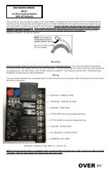
Numbered terminal block cover strip reference.<br />
The drawing below is for your reference on the correct positioning of the Telorvek fuel injection<br />
panel terminal block cover strips.<br />
When connecting wires to the panel be sure the numbered terminals match the drawing below.<br />
Bag #20 MASS AIR FLOW SENSOR (MAF): On a factory <strong>installation</strong>, this sensor is<br />
mounted in the intake air duct between the air cleaner and plenum. Plug the three gang black<br />
connector into the sensor and run the wires back to the panel. Connect the yellow MAF A->6 to<br />
#6 , black MAF B->26 to #26 and the orange wire MAF C->4 to #4.<br />
BAG #21 INTAKE AIR TEMPERATURE SENSOR (IAT): Install this sensor in the duct<br />
work between the Air Cleaner and the Plenum. Plug the gray connector in to the sensor and<br />
run the wires back to the panel. Connect the black wire IAT A->7 to #7 and the tan wire IAT B-<br />
>8 to #8.<br />
Bag #22 MAP SENSOR: After installing the MAP (Manifold Air Pressure) sensor on top of<br />
the plenum in the holes provided by GM make sure that the nipple from the sensor is sealed<br />
were it goes through the plenum. Plug the green connector into the sensor and run the wires<br />
back to the panel. Connect the black wire MAP A->7 to #7, lt green wire MAP B->9 to #9 and<br />
the gray wire MAP C->10 to #10.<br />
Bag #23 ENGINE COOLANT TEMPERATURE SENSOR: The sensor is located off to<br />
one side of the water pump. Plug the connector into the sensor and run the wires back to the<br />
panel. Connect the black wire ECT A->12 to #12 and the yellow wire ECT B->11 to #11.<br />
Bag #24 THROTTLE POSITION SENSOR (TPS): The TPS sensor is located on the<br />
right side of the throttle body. Plug the connector into the sensor and run the wires back to the<br />
panel. Connect the gray wire TPS A->14 to #14, black wire TPS B->12 to #12 and the dk blue<br />
wire TPS C->13 to #13.<br />
Bag #25 ELECTRONIC SPARK TIMING (Distributor): The LT-1 engine is normally<br />
supplied with an assembly/diagnostic test connection harness (about 2 feet long) running from<br />
the distributor to the middle of the right valve cover. Our harness is equipped with this<br />
connector. If you have the factory GM harness in place, discard our short assembly/diagnostic<br />
harness and plug directly into the GM harness.