The design of Padma Multipurpose Bridge - Bangladesh Group of ...
The design of Padma Multipurpose Bridge - Bangladesh Group of ...
The design of Padma Multipurpose Bridge - Bangladesh Group of ...

Create successful ePaper yourself
Turn your PDF publications into a flip-book with our unique Google optimized e-Paper software.
IABSE-JSCE Joint Conference on Advances in <strong>Bridge</strong> Engineering-II, August 8-10, 2010, Dhaka, <strong>Bangladesh</strong>. ISBN: 978-984-33-1893-0<br />
Amin, Okui, Bhuiyan (eds.)<br />
www.iabse-bd.org<br />
<strong>The</strong> <strong>design</strong> <strong>of</strong> <strong>Padma</strong> <strong>Multipurpose</strong> <strong>Bridge</strong> – challenges and solutions in<br />
<strong>design</strong> <strong>of</strong> the river spans<br />
S.H.R. Sham & M.J. Tapley<br />
AECOM Asia Company Ltd., Shatin, New Territories, Hong Kong<br />
ABSTRACT: At 6.15km in length the <strong>Padma</strong> <strong>Bridge</strong> will be a landmark structure in <strong>Bangladesh</strong> and one <strong>of</strong><br />
the great river crossings <strong>of</strong> the world. In <strong>design</strong>ing the bridge, consultant AECOM, has faced many major<br />
engineering challenges, particularly from the local environment. During the monsoon season the <strong>Padma</strong><br />
River can become a fast flowing river, susceptible to deep scour, requiring deep piled foundations. <strong>The</strong><br />
bridge site is also in an area <strong>of</strong> considerable seismic activity, leading to significant seismic loads being applied<br />
to the structure. To <strong>design</strong> the bridge, advanced computational analysis and engineering solutions have<br />
been employed, in order that the bridge will be able to meet the challenges <strong>of</strong> nature during its long life.<br />
1 INTRODUCTION<br />
1.1 General<br />
<strong>Padma</strong> <strong>Multipurpose</strong> <strong>Bridge</strong> will be a landmark feature in <strong>Bangladesh</strong> when completed. <strong>The</strong> <strong>Padma</strong> River is<br />
one <strong>of</strong> the world’s great rivers, with an overall width in excess <strong>of</strong> 6km at the crossing point. <strong>The</strong> <strong>design</strong> <strong>of</strong> a<br />
bridge has been a major challenge with the river changing in nature dramatically during the monsoon season,<br />
when the flow rate and major fluctuations in river bed level threatening to undermine any bridge piers. <strong>The</strong><br />
bridge is also to be constructed in a region <strong>of</strong> strong seismic activity, which when combined with the deep<br />
scour leads to a very onerous <strong>design</strong> condition.<br />
<strong>The</strong> <strong>Bangladesh</strong> <strong>Bridge</strong> Authority appointed AECOM as Design Consultant for the project. AECOM carried<br />
out a rigorous review <strong>of</strong> previous studies carried out on the bridge, before investigating in detail a series<br />
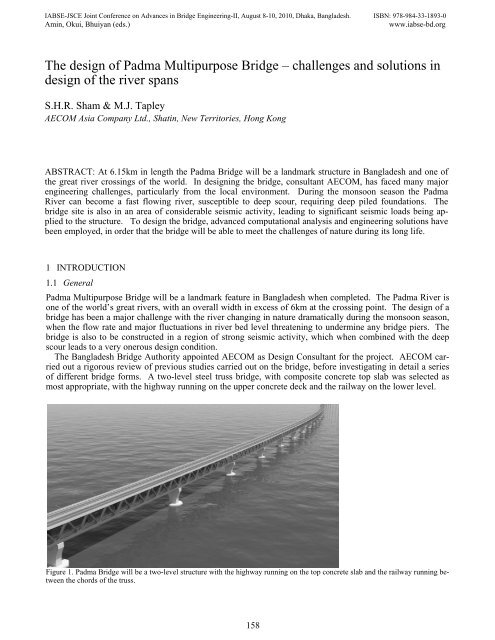
<strong>of</strong> different bridge forms. A two-level steel truss bridge, with composite concrete top slab was selected as<br />
most appropriate, with the highway running on the upper concrete deck and the railway on the lower level.<br />
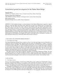
Figure 1. <strong>Padma</strong> <strong>Bridge</strong> will be a two-level structure with the highway running on the top concrete slab and the railway running between<br />
the chords <strong>of</strong> the truss.<br />
158
1.2 <strong>Multipurpose</strong> bridge<br />
<strong>Padma</strong> <strong>Bridge</strong> is a multipurpose structure carrying a highway, railway and utilities, including a gas pipeline<br />
and telecommunications cables. <strong>The</strong> two level structure <strong>of</strong> the bridge enables the road, railway and utilities to<br />
be arranged in a logical manner with good access for maintenance and inspection. <strong>The</strong> bridge is also provided<br />
with emergency access points in order to facilitate evacuation <strong>of</strong> a train on the bridge (Tapley, Sham &<br />
Holmberg, 2010).<br />
2 DESIGN CRITERIA<br />
2.1 Selection <strong>of</strong> suitable <strong>design</strong> codes<br />
Detailed investigations were carried out to determine the most suitable set <strong>of</strong> codes for <strong>design</strong>ing the bridge.<br />
<strong>The</strong> three options available were:<br />
<strong>The</strong> British bridge <strong>design</strong> code BS 5400<br />
<strong>The</strong> American code AASHTO LRFD <strong>Bridge</strong> Design Specifications<br />
<strong>The</strong> recently released Eurocodes<br />
BS 5400 was selected as it was felt that the highway loading criteria most closely corresponded to the situation<br />
expected in <strong>Bangladesh</strong>. Trucks are <strong>of</strong>ten heavily loaded, matching the load patterns predicted within the<br />
British standard. Eurocodes have been calibrated to give similar results to BS 5400, but some <strong>of</strong> the principles<br />
therein have not been studied in detail for such a major project outside <strong>of</strong> Europe and consequently were<br />
deemed unsuitable for the project, before a detailed study <strong>of</strong> the application <strong>of</strong> Eurocode in <strong>Bangladesh</strong> has<br />
been completed.<br />
<strong>The</strong> railway crossing the bridge will connect to the Indian National Railways and hence railway loading has<br />
been based the codes adopted on that system. More particularly the bridge has been <strong>design</strong>ed to be part <strong>of</strong> a<br />
Dedicated Freight Corridor (DFC), which implies an even higher loading than usual with a load <strong>of</strong> 32.5 tonne<br />
per axle.<br />
2.2 Seismic <strong>design</strong> criteria<br />
<strong>Padma</strong> <strong>Bridge</strong> will be constructed in an area <strong>of</strong> high seismic activity and consequently earthquakes are a critical<br />
consideration in the <strong>design</strong>. <strong>Bangladesh</strong> University <strong>of</strong> Engineering and Technology (BUET) has carried<br />
out a detailed study <strong>of</strong> the seismic hazard at the site to determine suitable seismic parameters for use in the<br />
<strong>design</strong>. Two levels <strong>of</strong> seismic hazard have been adopted:<br />
Operating Level Earthquake (OLE) has a return period <strong>of</strong> 100 years a 65% probability <strong>of</strong> being exceeded<br />
during that period. In such an earthquake the bridge will experience a peak ground acceleration<br />
<strong>of</strong> 0.052g and shall remain operational for all traffic after such an event.<br />
Contingency Level Earthquake (CLE) has a return period <strong>of</strong> 475 years with a 20% probability <strong>of</strong> being<br />
exceeded during the life <strong>of</strong> the bridge (100 years). <strong>The</strong> peak ground acceleration for such an event is<br />
0.144g in the dense sand at -120mPD. Any damage sustained from such an earthquake shall be easily<br />
detectable and capable <strong>of</strong> repair without demolition or component replacement.<br />
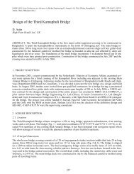
Figure 2. Response Spectra for CLE have been derived from the site specific study conducted by Pr<strong>of</strong>essor Ansary and also the<br />
Highway <strong>Bridge</strong> Design Specification Part V: Seismic Design by the Japan Road Association<br />
159
For such a major river crossing a step-by-step nonlinear time history analysis has been undertaken based on<br />
five AASHTO spectrum-compatible acceleration time histories representing the earthquake loading at the elevation<br />
<strong>of</strong> -120 m PD (refer to Figure 2).<br />
2.3 Foundation scour<br />
<strong>The</strong> other critical <strong>design</strong> criterion for the bridge has been scour. <strong>The</strong>re are large fluctuations in the volume <strong>of</strong><br />
water flowing along <strong>Padma</strong> River, having an impact both on the course <strong>of</strong> the river and the depth <strong>of</strong> river,<br />
particularly when bridge piers cause blockage to the flow. As a consequence extensive river training works<br />
will be required around the bridge (McLean, Neill & Oberhagemann, 2010) and the bridge piers have to be<br />
<strong>design</strong>ed for potentially severe scour conditions.<br />
Scour can essentially be divided into two parts:<br />
General scour – due to the action <strong>of</strong> the river and independent <strong>of</strong> any bridge constructed in the river;<br />
and<br />
Local scour – due to an obstruction to the flow such as a bridge pier.<br />
General scour has been studied by reviewing the data from the river over the last 40 years. River depth<br />
measurements have been taken on a regular basis and give a good indication <strong>of</strong> how the river changes during<br />
the monsoon season. For local scour model tests have been carried by sub consultant Northwest Hydraulic<br />
Consultants at its test facilities in Canada. Various foundation configurations have been studied, with the<br />
scour varying by over 7m depending on the piling configuration.<br />
For a 100-year return period, the riverbed level has been determined to be -46.7m PWD near the river bank<br />
and -35.0mPWD towards the centre <strong>of</strong> the river. From the experimentation carried out in Canada, local scour<br />
is estimated to deepen the scour by a further 15m for a raking pile arrangement, or 20m for fifteen vertical<br />
piles.<br />
2.4 Combining loads and environmental effects<br />
<strong>The</strong> load combinations given in BS 5400 Part 2 have generally been followed, but this code does not adequately<br />
cover how to combine seismic loading, ship impact and scour <strong>of</strong> the foundations. In particular the effect<br />
<strong>of</strong> scour has been given special consideration as the nature <strong>of</strong> the <strong>Padma</strong> River is unique. Scour can occur<br />
over prolonged periods and when infill <strong>of</strong> scour holes later occurs, the material that fills the holes is loose<br />
and remains uncompacted for a long period after the event. <strong>The</strong> loose material will be susceptible to liquefaction<br />
and therefore cannot be relied upon during a seismic event.<br />
With the liquefaction <strong>of</strong> the compacted fill material being a serious concern, scour with a 100-year return period<br />
has been adopted to be combined with loading from a seismic event. In the case <strong>of</strong> ship impact, liquefaction<br />
<strong>of</strong> the infill material is not considered a problem, and therefore a lesser return period <strong>of</strong> 10 years for<br />
scour has been adopted. Suitable partial safety factors have been selected to reflect the probability <strong>of</strong> occurrence<br />
<strong>of</strong> the events.<br />
3 SCHEME OPTIONS<br />
3.1 General<br />
In previous studies for the bridge a number <strong>of</strong> options for the bridge form had been examined, with the final<br />
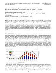
choice being a single-level extradosed bridge with spans <strong>of</strong> 180m. AECOM undertook detailed investigation<br />
<strong>of</strong> this bridge form by extensive finite element modelling, the model from which is shown in Figure 3. An extradosed<br />
bridge is a concrete box girder bridge, which uses stay cables to supplement the box girder thus reducing<br />
the structural depth. <strong>The</strong> railway however has very tight tolerances on displacement and rotation, and<br />
in order to meet these tolerances the girder would need to be stiffened, reducing the benefit <strong>of</strong> the stay cables<br />
and increasing the weight <strong>of</strong> the deck. With poor ground conditions and onerous loading combinations, it was<br />
critical to minimize the loads to the foundations, as the foundation costs would form a large proportion <strong>of</strong> the<br />
overall cost <strong>of</strong> the bridge. Consequently the extradosed bridge was not the preferred option.<br />
160
Figure 3. MIDAS model <strong>of</strong> an extradosed bridge<br />
3.2 Alternative bridge forms for two-level bridge<br />
Alternative concrete deck forms were investigated. Three examples are shown in Table 1, an extradosed concrete<br />
truss bridge, a concrete girder bridge and a steel truss bridge. In all cases a two-level structure was<br />
adopted as there are significant advantages over the single level structure:<br />
- Separate highway and railway envelopes enable improved operation, inspection and emergency<br />
evacuation procedures for the bridge.<br />
- <strong>The</strong> maximum permissible gradient on the railway is 0.5%, requiring long lengths <strong>of</strong> approach<br />
viaduct for the railway to descend to ground level. By reducing the structural depth beneath the<br />
railway (in a two level structure the railway runs inside the structural section), the length <strong>of</strong> the<br />
railway approach viaducts can be minimized.<br />
- Construction cost – a two-level structure is more efficient, with a much reduced overall width <strong>of</strong><br />
the structure.<br />
Table 1. Comparison <strong>of</strong> Alternative <strong>Bridge</strong> Forms<br />
<strong>Bridge</strong> Form Advantages Disadvantages<br />
Extradosed<br />
Truss <strong>Bridge</strong><br />
Concrete<br />
Truss structure enables<br />
significant weight savings<br />
over box girder solutions.<br />
Use <strong>of</strong> stay cables increases<br />
potential span<br />
lengths.<br />
Truss connection details<br />
would be difficult to<br />
construct leading to a<br />
longer construction period<br />
and additional cost.<br />
Heavier than steel deck<br />
solutions.<br />
Twin Box Girder with<br />
the Railway Carried by<br />
an In Situ Concrete Slab<br />
Spanning between the<br />
Boxes<br />
Steel Truss <strong>Bridge</strong> with<br />
Composite Concrete Top<br />
Slab<br />
Straightforward erection<br />
method, similar to other<br />
major bridges in <strong>Bangladesh</strong>.<br />
Steel truss is the lightest<br />
option, leading to a reduced<br />
number <strong>of</strong> piles<br />
and lowest overall cost.<br />
Truss is rigid and does<br />
not deflect excessively<br />
under rail loading.<br />
Heavy girder leads to increased<br />
demand on the<br />
foundations and shorter<br />
span lengths.<br />
Increased cost for foundations<br />
and deck due to<br />
additional weight<br />
Completely enclosed<br />
railway is a potential<br />
safety hazard.<br />
Steelwork will require<br />
repainting at regular intervals<br />
161
Analytical models were developed for each <strong>of</strong> the bridge forms to determine member sizes and in particular<br />
the weight <strong>of</strong> the superstructure. <strong>The</strong> steel truss bridge was found to be the most efficient with the lightest<br />
deck. Further studies were conducted on this option to determine the optimum span length. Overall deck<br />
weight and foundation loads were compared for three span lengths: 120m, 150m and 180m. From this data a<br />
construction cost was estimated for each span length with the optimum span length found to be 150m.<br />
<strong>The</strong> conclusion <strong>of</strong> the studies carried out on bridge deck, was that the steel truss bridge with a concrete top<br />
slab acting compositely with the truss, would be the most economic and suitable bridge form for the bridge.<br />
3.3 Foundation form<br />
In conjunction with these studies, further analysis has been carried out on the optimum form for the foundations<br />
(Sham, Yu & De Silva,2010). Two types <strong>of</strong> pile were investigated:<br />
- Large diameter (3m) raking steel tubular piles and<br />
- Large diameter cast in situ concrete bored piles<br />
<strong>The</strong> raking piles were found to be more efficient in resisting lateral loads resulting from earthquake motions.<br />
<strong>The</strong> lateral loads are resisted as axial forces in the steel piles. For the concrete bored piles the lateral<br />
loads are resisted by the flexural capacity <strong>of</strong> the piles. <strong>The</strong> very large bending moments generated by a seismic<br />
event dictated that insufficient flexural capacity could be generated by reinforcement alone, a permanent<br />
steel casing would required to enhance the capacity down to 10m below the riverbed level, which for a 100-<br />
year scour event would be -61mPWD. It would also be necessary to have more than fifteen 3.0m diameter<br />
vertical concrete piles, compared to eight raking steel tubular piles. <strong>The</strong> large number <strong>of</strong> piles increased the<br />
weight <strong>of</strong> the pile cap and also the local scour. All <strong>of</strong> these factors had an adverse effect on the cost and constructability<br />
<strong>of</strong> the foundations and hence the preferred solution was recommended to the raking steel tubular<br />
piles.<br />
4 METHODOLOGY OF SEISMIC DESIGN<br />
4.1 Analytical method and model<br />
A 3-dimensional non-linear time history dynamic analysis has been performed for the Main <strong>Bridge</strong> to determine<br />
the impact on the structure <strong>of</strong> seismic action. For the plan alignment <strong>of</strong> the main bridge, the subtended<br />
angle is less than 18 degree (the radius is 3000m and one module <strong>of</strong> the Main <strong>Bridge</strong> is 900m) and consequently<br />
the structure may be modelled as a straight line in plan.<br />
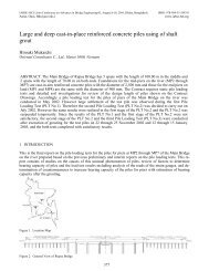
<strong>The</strong> behaviour <strong>of</strong> the bridge is complex due to its height (120m when the effects <strong>of</strong> scour are considered)<br />
and the large mass <strong>of</strong> the superstructure, pile caps and piles. A three dimensional non-linear time history dynamic<br />
analysis, using a modified Penzien model, has been adopted for carrying out the <strong>design</strong>. This model is<br />
divided into two parts, the structure and the free field soil. <strong>The</strong> interactions between the structure and the free<br />
field are simulated by lateral spring links. In order to determine the equivalent shear modulus and effective<br />
damping ratio between each layer <strong>of</strong> the soil, free field analysis has been carried out beforehand by program<br />
SHAKE. Subsequently, a 3-dimensional dynamic analysis has been carried out using the equivalent shear<br />
modulus and effective damping as input data.<br />
Figure 4. Modified Penzien Model and Results for Raking Pile Foundations<br />
162
<strong>The</strong> ground motions shown in Figure 2 were applied to the model to simulate the earthquake case and loads<br />
were generated in the piles and substructure accordingly. Other load combinations were considered such as<br />
ship impact and wind, although generally these effects were not found to be critical for the substructure, the<br />
seismic load combination dictated the <strong>design</strong>.<br />
A further global model was developed to investigate the global behaviour <strong>of</strong> the bridge. <strong>The</strong> bridge is divided<br />
into six span modules, each span <strong>of</strong> 150m. <strong>The</strong> global model examined an individual six span module<br />
and applied different levels <strong>of</strong> scour at each pier. A scour hole may form around an individual pier, or it can<br />
form around two or more piers. <strong>The</strong> global model looked at various combinations <strong>of</strong> scour on piers, in order<br />
to determine the critical axial load, shear and bending on the foundations <strong>of</strong> any particular pier.<br />
4.2 Seismic isolation<br />
Initial studies <strong>of</strong> the bridge were based on the deck being supported <strong>of</strong>f its piers by traditional sliding bearings,<br />
with the point fixity being the central pier <strong>of</strong> the six-span module. To avoid the fixed pier being heavily<br />
loaded during a seismic event by a longitudinal translation, shock transmission units (STUs) were provided at<br />
the free piers to ensure even load distribution between the piers. <strong>The</strong> loads applied to the piers were however<br />
still large and therefore as part <strong>of</strong> a Value Engineering process, alternative forms <strong>of</strong> articulation were examined.<br />
Isolation bearings have been used worldwide to mitigate seismic response by isolating structures from<br />
seismic input. Isolation bearings can accommodate thermal movements with minimum resistance, but will<br />
engage under seismic excitations. In this strategy, all primary structural members will remain elastic without<br />
any damage (or plastic hinging).<br />
Isolation bearings comprise the following key elements: an element that provides rigidity under service<br />
loads and provides lateral flexibility beyond service loads, an element that provides self-centring capability<br />
and an element that provides energy dissipation. <strong>The</strong>se key elements have to be properly <strong>design</strong>ed and fine<br />
tuned to achieve an optimal seismic behaviour.<br />
Analyses indicate that seismic forces can be greatly reduced by replacing the conventional pot bearings<br />
with isolation bearings. Friction pendulum bearings use the characteristics <strong>of</strong> a pendulum to lengthen the<br />
natural period <strong>of</strong> the isolated structure so as to reduce the input <strong>of</strong> earthquake forces. <strong>The</strong> damping effect due<br />
to sliding mechanism also helps mitigating earthquake response. Since earthquake induced displacements occur<br />
primarily in the bearings, lateral loads and shaking movements transmitted to the structure are greatly reduced.<br />
<strong>The</strong> reduced seismic loading generated at the top <strong>of</strong> the piers, leads to significantly reduced pile loads.<br />
With the conventional scheme <strong>of</strong> bearings and STUs, eight raking steel piles were required for each pier, with<br />
seismic isolation this number <strong>of</strong> piles can be reduced to six, leading to a saving in foundation cost <strong>of</strong> greater<br />
than 20%.<br />
Figure 5. Foundation arrangement for the seismic isolation scheme: six raking steel piles<br />
163
Figure 6. Typical cross section <strong>of</strong> the main bridge<br />
<strong>The</strong> impact <strong>of</strong> the seismic isolation scheme is not however limited to the substructure, the reduced seismic<br />
loading leads to reduction in section sizes for truss members, with an overall saving in truss steelwork <strong>of</strong><br />
greater than 4%.<br />
5 STRUCTURAL ANALYSIS OF SUPERSTRUCTURE<br />
5.1 <strong>Bridge</strong> deck cross section<br />
Figure 6 shows the typical bridge deck cross section. <strong>The</strong> highway runs along the concrete top slab, which is<br />
<strong>design</strong>ed to act compositely with the steel truss for live load effects. <strong>The</strong> railway runs between the truss<br />
planes at the lower level. It also runs on a concrete slab, the slab being supported by four steel beams, located<br />
beneath the wheels. <strong>The</strong> slab shown is structural and it will include fixings to connect to the track slab. <strong>The</strong><br />
cross section also shows the intended locations <strong>of</strong> utilities such as a high pressure gas pipeline and telecommunications<br />
ducts. Walkways will also be provided to each side <strong>of</strong> the railway for inspection and maintenance<br />
purposes and also emergency evacuation routes.<br />
<strong>The</strong> top chord, bottom chord and diagonal members <strong>of</strong> the main truss are in the form <strong>of</strong> hollow steel boxes.<br />
Plate thicknesses <strong>of</strong> the boxes vary depending on the location <strong>of</strong> the member. For thin plate thicknesses, longitudinal<br />
stiffeners are present to increase the efficiency <strong>of</strong> the section in resisting compressive stress. Box<br />
sections are also adopted for other members including the lower cross beams and upper cross beams. <strong>The</strong><br />
concrete roadway slab is reinforced concrete in the transverse direction, and is a prestressed concrete structure<br />
in the longitudinal direction. <strong>The</strong> longitudinal prestress will be carried out before the composite connection<br />
is established such that no additional stresses will be generated in the steel truss members. <strong>The</strong> railway<br />
concrete slab is reinforced concrete with no prestress. For all steel members except railway slab beams, the<br />
steel grade shall be S420M for plate thickness up to 40mm and S420ML for plate thickness over 40 mm. For<br />
railway slab beams, the steel grade shall be S355M.<br />
5.2 Global model<br />
Global models were developed using the analysis package MIDAS for the superstructure. <strong>The</strong>re were three<br />
models each representing different stages in the construction <strong>of</strong> the bridge:<br />
- An initial model <strong>of</strong> a simply supported span <strong>of</strong> the truss without concrete top slab, representing the<br />
stage when a single span <strong>of</strong> the truss is lifted into place (see Figure 7).<br />
164
Figure 7. Deck erection is anticipated to be by lifting and placing individual spans<br />
- A second model <strong>of</strong> a complete continuous module <strong>of</strong> the bridge without the concrete top slab, representing<br />
the stage when the steel trusses are connected together but prior to the placing <strong>of</strong> the concrete<br />
slab (see Figure 8).<br />
- A final stage model <strong>of</strong> a complete bridge module including concrete deck slab.<br />
Figure 8. Placement <strong>of</strong> the deck slab will take place after completion <strong>of</strong> the steel truss for a six-span module<br />
<strong>The</strong> bridge is modelled for the tightest bridge curvature, a radius <strong>of</strong> 3000m. Although the deck is curved the<br />
trusses are straight over each span, angular changes for deck curvature concentrated at the support points.<br />
Figure 9. Extract <strong>of</strong> analytical model <strong>of</strong> superstructure<br />
At each pier location, the truss is supported on elastic springs. Only translation stiffness is present and there<br />
is no rotational restraint as the truss is supported on seismic isolation devices. <strong>The</strong> stiffness <strong>of</strong> these elastic<br />
springs represents the stiffness <strong>of</strong> the pile group. Figure 9 shows part <strong>of</strong> the global model and the location <strong>of</strong><br />
the support springs. <strong>The</strong> spring values are derived in a separate pile group analysis and are given in Table 2.<br />
Table 2. Spring stiffness for analytical model <strong>of</strong> superstructure<br />
Stiffness Spring Constant<br />
(scour @ -20 mPD)<br />
Spring Constant<br />
(scour @ -62 mPD)<br />
Transverse 52 kN/mm 33 kN/mm<br />
Longitudinal 19 kN/mm 12 kN/mm<br />
Vertical<br />
1700 kN/mm<br />
Spring support<br />
Two further models were used in the analysis <strong>of</strong> the superstructure.<br />
- Plate element model. <strong>The</strong> concrete top slab includes longitudinal prestressing tendons to ensure there is<br />
no significant cracking <strong>of</strong> the slab over the piers when acting compositely with steel truss. A plate<br />
element model was developed to investigate the stresses in the slab, with the steelwork and slab mem-<br />
165
ers being modelled discretely. <strong>The</strong> model was also used to investigate the effects <strong>of</strong> shrinkage and<br />
creep <strong>of</strong> the concrete and also the effect <strong>of</strong> transverse wind acting on the slab.<br />
- Concrete Slab Solid Element Model. In order to investigate the effect <strong>of</strong> highway loading on the concrete<br />
deck slab, a separate model <strong>of</strong> solid elements was developed to determine the critical bending moments<br />
and shears in the slab. To limit the overall thickness <strong>of</strong> the slab, transverse ribs at 2m centres<br />
are provided to enhance the transverse bending capacity <strong>of</strong> the deck. Figure 10 shows the solid element<br />
model.<br />
Figure 10. Solid element model <strong>of</strong> the deck slab with 45 units <strong>of</strong> HB vehicle load applied<br />
5.3 Railway deck<br />
<strong>The</strong> railway will be supported by four steel beams acting compositely with a concrete deck slab. A special<br />
model was prepared, composed <strong>of</strong> four longitudinal composite sections, connected by transverse members<br />
and cross beam at each end. <strong>The</strong> composite sections are steel universal beams. <strong>The</strong> width <strong>of</strong> concrete slab is<br />
1295mm and height <strong>of</strong> 200 mm. For the steel girder, the adopted steel section is UB - 914 x 419 x 388.<br />
Figure 11. Modelling <strong>of</strong> railway track slab and its connection to the cross girders between the truss lower chords<br />
Beam end releases are added at the connection point <strong>of</strong> composite decks and cross beams, so that no hogging<br />
moment is induced at these points on the composite decks and to simulate a shear connection between the<br />
deck and cross beams (see Figure 11). Three different types <strong>of</strong> railway live load have been applied on the<br />
composite deck section (railway deck) to simulate different wheel patterns. Since the bridge is curved on<br />
plan, there exists a maximum transverse <strong>of</strong>fset <strong>of</strong> 500 mm between the railway alignment and composite deck<br />
centreline at the tightest radius. Consequently for each load type, two cases are considered: one for the railway<br />
load applied along the deck centreline, and the other for the railway load when shifted transversely by<br />
500 mm.<br />
6 CONCLUSIONS<br />
<strong>The</strong> <strong>Padma</strong> <strong>Multipurpose</strong> <strong>Bridge</strong> will stand as a landmark structure in <strong>Bangladesh</strong>, not only providing a vital<br />
communications link, but also signalling another milestone engineering solution in a region <strong>of</strong> extreme environmental<br />
hazards. <strong>The</strong> combination <strong>of</strong> deep scour and regular seismic activity has required <strong>design</strong> consultant<br />
AECOM to apply state-<strong>of</strong>-the-art bridge technologies to robustly integrate bridge <strong>design</strong> with construction<br />
to ensure the bridge will not only serve the <strong>Bangladesh</strong> people <strong>of</strong> today, but also many generations to come.<br />
7 ACKNOWLEDGMENTS<br />
This paper is submitted with the permission <strong>of</strong> the <strong>Bangladesh</strong> <strong>Bridge</strong> Authority, the Government <strong>of</strong> the<br />
<strong>Bangladesh</strong>.<br />
166
REFERENCES<br />
McLean, D., Neill, C. & Oberhagemann, K. 2010. Design <strong>of</strong> River Training Works for <strong>Padma</strong> <strong>Multipurpose</strong> <strong>Bridge</strong>, <strong>Bangladesh</strong>.<br />
Proc. IABSE – JSCE Conference, Dhaka, 10-12 August 2010<br />
Sham, S.H.R., Yu & De Silva, S. 2010. Foundation Design Methodology for <strong>Padma</strong> Main <strong>Bridge</strong>. Proc. IABSE – JSCE Conference,<br />
Dhaka, 10-12 August 2010<br />
Tapley, M.J., Sham, S.H.R. & Holmberg, R.A. 2010. Developing the Operations and Maintenance Strategy for the <strong>Padma</strong> <strong>Multipurpose</strong><br />
<strong>Bridge</strong>. Proc. IABSE-JSCE Conference, Dhaka, 10-12 August2010<br />
167