Recent technology of prestressed concrete bridges in Japan Hiroshi ...
Recent technology of prestressed concrete bridges in Japan Hiroshi ...
Recent technology of prestressed concrete bridges in Japan Hiroshi ...

Create successful ePaper yourself
Turn your PDF publications into a flip-book with our unique Google optimized e-Paper software.
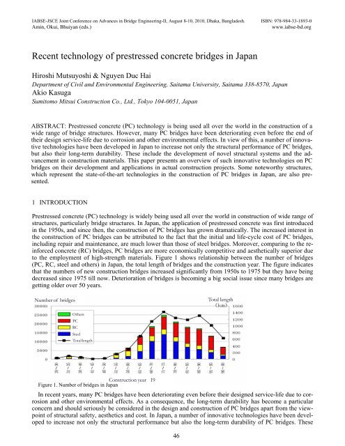
IABSE-JSCE Jo<strong>in</strong>t Conference on Advances <strong>in</strong> Bridge Eng<strong>in</strong>eer<strong>in</strong>g-II, August 8-10, 2010, Dhaka, Bangladesh. ISBN: 978-984-33-1893-0Am<strong>in</strong>, Okui, Bhuiyan (eds.)www.iabse-bd.org<strong>Recent</strong> <strong>technology</strong> <strong>of</strong> <strong>prestressed</strong> <strong>concrete</strong> <strong>bridges</strong> <strong>in</strong> <strong>Japan</strong><strong>Hiroshi</strong> Mutsuyoshi & Nguyen Duc HaiDepartment <strong>of</strong> Civil and Environmental Eng<strong>in</strong>eer<strong>in</strong>g, Saitama University, Saitama 338-8570, <strong>Japan</strong>Akio KasugaSumitomo Mitsui Construction Co., Ltd., Tokyo 104-0051, <strong>Japan</strong>ABSTRACT: Prestressed <strong>concrete</strong> (PC) <strong>technology</strong> is be<strong>in</strong>g used all over the world <strong>in</strong> the construction <strong>of</strong> awide range <strong>of</strong> bridge structures. However, many PC <strong>bridges</strong> have been deteriorat<strong>in</strong>g even before the end <strong>of</strong>their design service-life due to corrosion and other environmental effects. In view <strong>of</strong> this, a number <strong>of</strong> <strong>in</strong>novativetechnologies have been developed <strong>in</strong> <strong>Japan</strong> to <strong>in</strong>crease not only the structural performance <strong>of</strong> PC <strong>bridges</strong>,but also their long-term durability. These <strong>in</strong>clude the development <strong>of</strong> novel structural systems and the advancement<strong>in</strong> construction materials. This paper presents an overview <strong>of</strong> such <strong>in</strong>novative technologies on PC<strong>bridges</strong> on their development and applications <strong>in</strong> actual construction projects. Some noteworthy structures,which represent the state-<strong>of</strong>-the-art technologies <strong>in</strong> the construction <strong>of</strong> PC <strong>bridges</strong> <strong>in</strong> <strong>Japan</strong>, are also presented.1 INTRODUCTIONPrestressed <strong>concrete</strong> (PC) <strong>technology</strong> is widely be<strong>in</strong>g used all over the world <strong>in</strong> construction <strong>of</strong> wide range <strong>of</strong>structures, particularly bridge structures. In <strong>Japan</strong>, the application <strong>of</strong> <strong>prestressed</strong> <strong>concrete</strong> was first <strong>in</strong>troduced<strong>in</strong> the 1950s, and s<strong>in</strong>ce then, the construction <strong>of</strong> PC <strong>bridges</strong> has grown dramatically. The <strong>in</strong>creased <strong>in</strong>terest <strong>in</strong>the construction <strong>of</strong> PC <strong>bridges</strong> can be attributed to the fact that the <strong>in</strong>itial and life-cycle cost <strong>of</strong> PC <strong>bridges</strong>,<strong>in</strong>clud<strong>in</strong>g repair and ma<strong>in</strong>tenance, are much lower than those <strong>of</strong> steel <strong>bridges</strong>. Moreover, compar<strong>in</strong>g to the re<strong>in</strong>forced<strong>concrete</strong> (RC) <strong>bridges</strong>, PC <strong>bridges</strong> are more economically competitive and aesthetically superior dueto the employment <strong>of</strong> high-strength materials. Figure 1 shows relationship between the number <strong>of</strong> <strong>bridges</strong>(PC, RC, steel and others) <strong>in</strong> <strong>Japan</strong>, the total length <strong>of</strong> <strong>bridges</strong> and the construction year. The figure <strong>in</strong>dicatesthat the numbers <strong>of</strong> new construction <strong>bridges</strong> <strong>in</strong>creased significantly from 1950s to 1975 but they have be<strong>in</strong>gdecreased s<strong>in</strong>ce 1975 till now. Deterioration <strong>of</strong> <strong>bridges</strong> is becom<strong>in</strong>g a big social issue s<strong>in</strong>ce many <strong>bridges</strong> aregett<strong>in</strong>g older over 50 years.Number <strong>of</strong> <strong>bridges</strong>Total lengthOthersPCRCSteelTotal lengthConstruction year 19 Figure 1. Number <strong>of</strong> <strong>bridges</strong> <strong>in</strong> <strong>Japan</strong>In recent years, many PC <strong>bridges</strong> have been deteriorat<strong>in</strong>g even before their designed service-life due to corrosionand other environmental effects. As a consequence, the long-term durability has become a particularconcern and should seriously be considered <strong>in</strong> the design and construction <strong>of</strong> PC <strong>bridges</strong> apart from the viewpo<strong>in</strong>t<strong>of</strong> structural safety, aesthetics and cost. In <strong>Japan</strong>, a number <strong>of</strong> <strong>in</strong>novative technologies have been developedto <strong>in</strong>crease not only the structural performance but also the long-term durability <strong>of</strong> PC <strong>bridges</strong>. These46
<strong>in</strong>clude the development <strong>of</strong> novel structural system such as external prestress<strong>in</strong>g, highly eccentric externaltendons and extradosed prestress<strong>in</strong>g.This paper presents an overview <strong>of</strong> such <strong>in</strong>novative technologies <strong>of</strong> PC <strong>bridges</strong> <strong>in</strong>clud<strong>in</strong>g a brief detail <strong>of</strong>their development and background as well as their applications <strong>in</strong> actual construction projects. In addition,some noteworthy structures, which represent the state-<strong>of</strong>-the-art technologies <strong>in</strong> the construction <strong>of</strong> PC<strong>bridges</strong> <strong>in</strong> <strong>Japan</strong> are also presented.2 DEVELOPMENT OF NOVEL STRUCTURAL SYSTEMS IN PC BRIDGESExternal prestress<strong>in</strong>g technique is widely be<strong>in</strong>g used <strong>in</strong> the construction <strong>in</strong>dustry. Externally <strong>prestressed</strong> PC<strong>bridges</strong> are designed with prestress<strong>in</strong>g tendons placed outside the <strong>concrete</strong> section, but still rema<strong>in</strong><strong>in</strong>g with<strong>in</strong>the bounds <strong>of</strong> the cross section <strong>of</strong> girder (Figure 2). The concept <strong>of</strong> external prestress<strong>in</strong>g has become <strong>in</strong>creas<strong>in</strong>glypopular <strong>in</strong> the constructions <strong>of</strong> medium- and long-span <strong>bridges</strong> due to its several advantages such as reducedweb thickness, possibility to control and adjust tendon forces, and ease <strong>of</strong> <strong>in</strong>spection <strong>of</strong> tendons dur<strong>in</strong>gconstruction. The <strong>Japan</strong> Highway Public Corporation (abbreviated for JH; it is changed to three highwaycompanies at present), which governed most <strong>of</strong> the highway <strong>bridges</strong> <strong>in</strong> <strong>Japan</strong>, has actively adopted the concept<strong>of</strong> fully external tendons for box girder <strong>bridges</strong> (Figure 2) s<strong>in</strong>ce 1999 due to the improved durability performancecompared to that <strong>of</strong> <strong>in</strong>ternally grouted tendons. It is <strong>of</strong> importance to note that, recently, a new construction<strong>of</strong> PC <strong>bridges</strong> with <strong>in</strong>ternally grouted tendons has been forbidden by the JH due to the bad quality <strong>of</strong>grout<strong>in</strong>g <strong>of</strong> <strong>in</strong>ternal tendons <strong>in</strong> some exist<strong>in</strong>g PC <strong>bridges</strong> [1]. For the better performance <strong>of</strong> the externally <strong>prestressed</strong><strong>concrete</strong> <strong>bridges</strong>, various new technologies have recently been developed <strong>in</strong> <strong>Japan</strong>.External Tendons(a) Ord<strong>in</strong>ary external tendonDeviator BlocksDiaphragm Anchorage(b) Highly eccentric external tendonFigure 2. Typical layout <strong>of</strong> an external PC box girderbidFigure 3. Ord<strong>in</strong>ary vs. highly eccentric external tendon2.1 PC Bridges with highly eccentric external tendonsAlthough externally <strong>prestressed</strong> PC <strong>bridges</strong> are well recognized to have several advantages, however, theyhave lower flexural strength compared to that <strong>of</strong> <strong>bridges</strong> with <strong>in</strong>ternally bonded tendons [2]. This is due to thesmaller tendon eccentricity, which is limited by the bounds <strong>of</strong> <strong>concrete</strong> section <strong>of</strong> girder (i.e., at the bottomslab <strong>in</strong> case <strong>of</strong> box-girder <strong>bridges</strong>) as well as the reduction <strong>in</strong> tendon eccentricity at the ultimate flexural failure(so-called second-order effect). One possible method <strong>of</strong> enhanc<strong>in</strong>g the flexural strength <strong>of</strong> externally PCstructures is to make the tendons highly eccentricity (Figure 3). This k<strong>in</strong>d <strong>of</strong> construction is possible onlywhen external prestress<strong>in</strong>g is used, s<strong>in</strong>ce this allows the tendons to be placed outside the <strong>concrete</strong> section <strong>of</strong>girder. In this concept, the compressive forces are taken by <strong>concrete</strong> and the tensile forces by external tendons,thus tak<strong>in</strong>g advantages <strong>of</strong> both materials effectively [3].Figure 4. Load<strong>in</strong>g test <strong>of</strong> s<strong>in</strong>gle span girder with highlyeccentric external tendons47Figure 5. L<strong>in</strong>ear transformation <strong>of</strong> tendon layout
There has been extensive research conducted at Saitama University both analytically and experimentally tostudy the fundamental behavior <strong>of</strong> girders with highly eccentric external tendons [4, 5, 6]. From the test results<strong>of</strong> s<strong>in</strong>gle-span beams (Figure 4), it was found that by <strong>in</strong>creas<strong>in</strong>g tendon eccentricity, the flexural strengthcan be significantly improved or, conversely, the amount <strong>of</strong> prestress<strong>in</strong>g reduced; the result is more economicalstructures. By extend<strong>in</strong>g the concept <strong>of</strong> highly eccentric external tendons to cont<strong>in</strong>uous girders, the structuralperformance can be further improved. In addition, the girders consist<strong>in</strong>g <strong>of</strong> l<strong>in</strong>early transformed tendonpr<strong>of</strong>ile were found to have the same overall flexural behavior (Figure 5). This gives the designer to take advantage<strong>of</strong> arrang<strong>in</strong>g the external tendon layout freely, depend<strong>in</strong>g on the site conditions.To verify the application <strong>of</strong> this concept to the segmental construction method, the behavior <strong>of</strong> segmentalgirders with highly eccentric external tendons was also <strong>in</strong>vestigated and found to be nearly the same as that <strong>of</strong>monolithically cast girders. Hence, this gives considerable flexibility <strong>in</strong> select<strong>in</strong>g the method <strong>of</strong> constructionwhen design<strong>in</strong>g the <strong>bridges</strong> with highly eccentric external tendons. One <strong>of</strong> the concerns raised for this type <strong>of</strong>structure was the shear capacity as the girder height is considerably reduced. It was verified, however, fromthe experiment on shear characteristic <strong>of</strong> model specimens that the shear capacity <strong>of</strong> the girder with highlyeccentric external tendons is much higher than that <strong>of</strong> the conventional girders due to the large <strong>in</strong>crease <strong>of</strong>tensile force <strong>in</strong> external tendons.The world’s first application <strong>of</strong> the prestress<strong>in</strong>g with highly eccentric external tendon to a cont<strong>in</strong>uous-spangirder was <strong>in</strong> the construction <strong>of</strong> the Boukei Bridge <strong>in</strong> Hokkaido, <strong>Japan</strong>. Consider<strong>in</strong>g the site conditions, thebridge was designed with a two-span cont<strong>in</strong>uous and unsymmetrical girder hav<strong>in</strong>g a total length <strong>of</strong> 57 m asshown <strong>in</strong> Figure 6. The effective width <strong>of</strong> the bridge varies from 3.0 m at the abutments to 6.0 m at the centralpier. A completed view <strong>of</strong> the bridge is shown <strong>in</strong> Figure 7.Figure 6. Layout diagram and dimension <strong>of</strong> the Boukei BridgeFigure 7. View <strong>of</strong> the completed Boukei BridgeFigure 8. Schematic view <strong>of</strong> layout <strong>of</strong> external tendonThe characteristic <strong>of</strong> this <strong>in</strong>novative bridge is that the external tendon layout takes the similar shape <strong>of</strong> thebend<strong>in</strong>g moment diagram as shown <strong>in</strong> Figure 8. The structure was designed to form a pseudo truss, with thema<strong>in</strong> girder made <strong>of</strong> <strong>concrete</strong> as compression chords, the external tendons as tension chords, and the steel deviatorsas diagonal members. This allowed the girder height to be reduced significantly, thus mak<strong>in</strong>g thebridge lightweight. The external tendons are placed below the girder <strong>in</strong> the midspan region by means <strong>of</strong> steelstruts, the function <strong>of</strong> which is similar to a truss. At the <strong>in</strong>termediate support region, it is placed above thebridge deck and covered with a f<strong>in</strong>-shaped <strong>concrete</strong> web member. The comb<strong>in</strong>ation <strong>of</strong> the subtended tendonsand the f<strong>in</strong>-shaped <strong>concrete</strong> web makes this bridge a unique one with aesthetically pleas<strong>in</strong>g appearance.Although hav<strong>in</strong>g several advantages, PC <strong>bridges</strong> with highly eccentric external tendons should be carefullydesigned and constructed concern<strong>in</strong>g the follow<strong>in</strong>g important po<strong>in</strong>ts. S<strong>in</strong>ce the ma<strong>in</strong> girder, struts and highlyeccentric external tendons form a truss <strong>in</strong> this type <strong>of</strong> structure, construction precision <strong>of</strong> <strong>in</strong>dividual membershas a significant <strong>in</strong>fluence on the structure. For this, it is necessary to give special consideration to the tech-48
niques and procedures for construct<strong>in</strong>g the falsework, formwork and external tendons. Moreover, the vibrationcharacteristics under service load may be <strong>of</strong> concern due to the smaller stiffness <strong>of</strong> the ma<strong>in</strong> girdercaused by the reduction <strong>in</strong> girder height. Nevertheless, the authors believe that this new concept <strong>of</strong> prestress<strong>in</strong>gwould pave way to a wider use <strong>of</strong> external prestress<strong>in</strong>g <strong>technology</strong> <strong>in</strong> the construction <strong>in</strong>dustry, lead<strong>in</strong>g toimproved structural performance as well as cost effective PC <strong>bridges</strong>. The research is <strong>in</strong> progress regard<strong>in</strong>gthe possibility <strong>of</strong> apply<strong>in</strong>g these k<strong>in</strong>d <strong>of</strong> structures to highway <strong>bridges</strong> us<strong>in</strong>g precast segmental construction.2.2 Extradosed PC BridgesAn extradosed prestress<strong>in</strong>g concept, which was first proposed by Mathivat <strong>in</strong> France [7], is a new type <strong>of</strong>structural system <strong>in</strong> which the tendons are <strong>in</strong>stalled outside and above the ma<strong>in</strong> girder and deviated by shorttowers located at supports. Consider<strong>in</strong>g its def<strong>in</strong>ition, this type <strong>of</strong> bridge is placed between cable-stayed<strong>bridges</strong> and ord<strong>in</strong>ary girder <strong>bridges</strong> with <strong>in</strong>ternal or external tendons.Extradosed PC <strong>bridges</strong> have several positive characteristics. The girder height may be lower than that <strong>of</strong>ord<strong>in</strong>ary girder <strong>bridges</strong>, thus reduc<strong>in</strong>g self-weight <strong>of</strong> structures. As shown <strong>in</strong> Figure 9, the ratio <strong>of</strong> the girderheight to the span length (H/L) <strong>in</strong> extradosed <strong>bridges</strong> ranges between 1/15 and 1/35, while it is approximately1/15~1/17 for box-girder <strong>bridges</strong>. Compar<strong>in</strong>g to cable-stayed <strong>bridges</strong>, the height <strong>of</strong> the ma<strong>in</strong> tower <strong>in</strong> extradosed<strong>bridges</strong> is lower; hence, a reduction <strong>in</strong> labor costs <strong>of</strong> construction can be achieved.Because <strong>of</strong> a lower ma<strong>in</strong> tower <strong>in</strong> extradosed <strong>bridges</strong>, vertical loads are partly resisted by ma<strong>in</strong> girders andstress variations <strong>in</strong> stay cables produced by live loads are smaller than those <strong>in</strong> cable-stayed <strong>bridges</strong>. This isquite similar to the behavior <strong>of</strong> box-girder <strong>bridges</strong>, where the ma<strong>in</strong> girder itself has a decisive <strong>in</strong>fluence on thestructure rigidity and live loads produce only limited stress variations <strong>in</strong> tendons. Based on these facts, the <strong>Japan</strong>Road Association [8] has recommended that the safety factor for the stayed cables <strong>in</strong> extradosed <strong>bridges</strong>under design loads shall be taken as 1.67 (0.6 fpu; fpu = tensile strength <strong>of</strong> tendons), which is same as that fortendons <strong>in</strong> ord<strong>in</strong>ary girder <strong>bridges</strong>. For cable-stayed <strong>bridges</strong>, this value is specified to be 2.5 (0.4 fpu).The major difference among box-girder, extradosed and cable-stayed <strong>bridges</strong> can be further revealed bycompar<strong>in</strong>g the relationship between materials used with span lengths. In box-girder <strong>bridges</strong>, the average <strong>concrete</strong>thickness <strong>in</strong>creases with the span length, s<strong>in</strong>ce the girder height is a function <strong>of</strong> the span length. On theother hand, <strong>in</strong> cable-stayed <strong>bridges</strong>, there is almost no <strong>in</strong>crease <strong>in</strong> the average depth <strong>of</strong> <strong>concrete</strong> because thegirder height is generally designed to be 2.0~2.5 m, regardless <strong>of</strong> the span length. It is <strong>in</strong>terest<strong>in</strong>g to note thatextradosed <strong>bridges</strong> are placed between these two types, and the rate <strong>of</strong> <strong>in</strong>crease is also thought to be midwaybetween the rates <strong>of</strong> the other two types <strong>of</strong> <strong>bridges</strong>.Similarly, with <strong>in</strong>creas<strong>in</strong>g span length, the quantity <strong>of</strong> prestress<strong>in</strong>g tendons <strong>in</strong> box-girder <strong>bridges</strong> shows amore <strong>in</strong>crease than that <strong>in</strong> cable-stayed <strong>bridges</strong>, whereas extradosed <strong>bridges</strong> yield the <strong>in</strong>termediate value betweenthe other two types.From the above discussion, it can be concluded that an extradosed bridge is similar <strong>in</strong> construction and appearanceto a cable-stayed bridge. In the light <strong>of</strong> structural properties, however, an extradosed bridge is closedto ord<strong>in</strong>ary PC girder <strong>bridges</strong>, and the design specifications may be considered to be the same for both types<strong>of</strong> <strong>bridges</strong>.hLHTHTTTs<strong>in</strong>θθTcosθH/L ≈ 1/15 ∼ 1/17h ≈ L/15H/L ≈ 1/15 ∼ 1/35External prestress<strong>in</strong>gExtradosed prestress<strong>in</strong>gThHCable-stayed bridgeTh = L/5H = 2.0 ∼ 2.5 mT Ts<strong>in</strong>θθTcosθFigure 9. Comparison among externally box-girder, extradosed and cable-stayed PC <strong>bridges</strong>49
2.3 Difference between cable-stayed <strong>bridges</strong> and extradosed <strong>bridges</strong>The differences between cable-stayed <strong>bridges</strong> and extradosed <strong>bridges</strong> have be<strong>in</strong>g debated by numerousresearchers. Both types <strong>of</strong> these <strong>bridges</strong> have structures that use stay cables as re<strong>in</strong>forcements. However, <strong>in</strong>case <strong>of</strong> extradosed <strong>bridges</strong> it is neccessary to provide a structural rationale rather than simply assum<strong>in</strong>g anallowable stress <strong>of</strong> 0.6fpu <strong>in</strong> design <strong>of</strong> the <strong>bridges</strong>. In this po<strong>in</strong>t, attention focuses on the distribution ratio <strong>of</strong>vertical load carried by the girders and the stay cables. Figure 10 shows the relationship between thedistribution ratio <strong>of</strong> vertical load (β) and maximum stress change <strong>of</strong> stay cable due to design live load (∆σ L )<strong>of</strong> various cable-stayed <strong>bridges</strong> and extradosed <strong>bridges</strong> constructed <strong>in</strong> <strong>Japan</strong>. As shown <strong>in</strong> the figure, it isdifficult to clearly dist<strong>in</strong>guish between extradosed <strong>bridges</strong> and cable-stayed <strong>bridges</strong> <strong>in</strong> terms <strong>of</strong> structuralmechanics s<strong>in</strong>ce many <strong>of</strong> the cable-stayed <strong>bridges</strong> are very similar to extradosed <strong>bridges</strong>. In design<strong>in</strong>g staycables, stress change due to design live loads provides an effective <strong>in</strong>dex that can be easily determ<strong>in</strong>edthrough the design process.Strand SystemEstimationDistribution Ratio <strong>of</strong> Vertical Load β (%)Figure 10. Distribution ratio <strong>of</strong> verticalload and stress change <strong>of</strong> stay cableFigure 11. Allowable tensile stress andstress change <strong>of</strong> stay cable2.4 Approximated design method for stay cablesThe fatigue limit state is usually critical <strong>in</strong> the design <strong>of</strong> stay cables. When bridge structures re<strong>in</strong>forced by staycables, the design <strong>of</strong> stay cables would be structural rationale by focus<strong>in</strong>g on the stress change <strong>in</strong> the staycables rather than def<strong>in</strong><strong>in</strong>g whether <strong>bridges</strong> are cable-stayed or extradosed by assum<strong>in</strong>g allowable stress forthe stay cables. This would make it possible to design each stay cable separately and enable the allowablestress to be set <strong>in</strong>dividually for each stay cable. Unlike suspension <strong>bridges</strong>, the stress change <strong>in</strong> a cable-stayedbridge will differ depend<strong>in</strong>g on the stay cables and it is not rational to def<strong>in</strong>e the allowable stress us<strong>in</strong>g a s<strong>in</strong>glevalue <strong>of</strong> 0.4fpu. This is reflected <strong>in</strong> the "Specifications for Design and Construction <strong>of</strong> Cable-Stayed PCBridges and Extradosed Bridges" [9]. The specification allows two k<strong>in</strong>ds <strong>of</strong> design method. Method A is normalfatigue design us<strong>in</strong>g fatigue load and design lifetime <strong>of</strong> a bridge. However, it is usually difficult to estimatethe amount <strong>of</strong> future traffic and heavy trucks, especially <strong>in</strong> local roads. In that case, method B us<strong>in</strong>gstress change <strong>in</strong> stay cables due to design vehicular live loads is <strong>in</strong>troduced. Figure 11 shows the relationshipbetween the allowable tensile stress <strong>of</strong> stay cable for highway <strong>bridges</strong> and the stress change due to live load∆σ L regulated <strong>in</strong> the specifications. The difference <strong>in</strong> fatigue strength between prefabricated wire type andstrand type is considered. By us<strong>in</strong>g prior experience <strong>in</strong> <strong>Japan</strong> with cable-stayed, extradosed and similar<strong>bridges</strong> hav<strong>in</strong>g spans <strong>of</strong> up to about 250 m, method B is def<strong>in</strong>ed so as to ensure adequate safety <strong>in</strong> comparisonwith <strong>bridges</strong> designed us<strong>in</strong>g method A.Fatigue design was performed for the estimation l<strong>in</strong>e <strong>of</strong> stress range for two million cycles (∆σ 2E6 ) <strong>in</strong>clud<strong>in</strong>gsecondary flexural bend<strong>in</strong>g due to girder deflection (determ<strong>in</strong>ed accord<strong>in</strong>g to design conditions on a designservice life <strong>of</strong> 50 years and average daily traffic <strong>of</strong> 70,000 mix<strong>in</strong>g 50% trucks) by us<strong>in</strong>g the structuralmodels <strong>of</strong> the Odawara Blueway bridge, the Tsukuhara bridge, and the Ibi River bridge as shown <strong>in</strong> Figure10. Based on the calculations the stress change due to fatigue load is about 1/3 <strong>of</strong> that due to design live loadsand the stress level due to secondary flexural bend<strong>in</strong>g is the same as that due to axial forces <strong>of</strong> stay cables. It isnoted that the estimation l<strong>in</strong>e <strong>of</strong> ∆σ 2E6 is assumed to be 2(1/3)(Max∆σ L ). The safety marg<strong>in</strong> <strong>of</strong> method B canbe confirmed by compar<strong>in</strong>g ∆σ 2Ε6 with fatigue strength (f scrd ) divided by a safety factor (γ b ).In the stay cables designed by method B, ∆σ L is determ<strong>in</strong>ed to require a safety factor <strong>of</strong> about 2.0 for ∆σ 2E6with respect to f scrd /γ b , <strong>in</strong> order to take <strong>in</strong>to consideration the fact that the method <strong>in</strong>cludes more uncerta<strong>in</strong>ties50
than method A, and <strong>in</strong> order that the safety <strong>of</strong> stay cables does not vary greatly from that <strong>of</strong> cable-stayed andextradosed <strong>bridges</strong> constructed to date. In the most <strong>of</strong> extradosed <strong>bridges</strong> and some cable-stayed <strong>bridges</strong>, thetensile stress <strong>of</strong> 0.6fpu can be used because stress changes are low (20 to 50N/mm 2 ). Moreover the most rationalpo<strong>in</strong>t <strong>of</strong> this specification is that we can choose the tensile stress <strong>in</strong> each stay cable from 0.4fpu to0.6fpu cont<strong>in</strong>uously. This is based on the concept that one value <strong>of</strong> tensile stress <strong>in</strong> one bridge is not structurallyrational.2.5 Application <strong>of</strong> extradosed prestress<strong>in</strong>gNowadays, a great number <strong>of</strong> PC <strong>bridges</strong> us<strong>in</strong>g extradosed prestress<strong>in</strong>g are be<strong>in</strong>g constructed <strong>in</strong> <strong>Japan</strong>.Attempts are also be<strong>in</strong>g made to apply this structural concept to other <strong>in</strong>novated technologies, such ascorrugated steel web, precast segmental construction, and comb<strong>in</strong>ed structures with steel girders.Figure 12 shows the Odawara Blue-Way Bridge, which is the first extradosed PC box girder bridge <strong>in</strong> theworld and was completed <strong>in</strong> 1994. This bridge was designed with a three-span cont<strong>in</strong>uous box-girder withextradosed prestress<strong>in</strong>g, hav<strong>in</strong>g a middle span length <strong>of</strong> 122 m, a tower height (h) <strong>of</strong> 10.5 m, and a girderheight at supports (H) <strong>of</strong> 3.5 m. The ratios <strong>of</strong> h/L and H/L are approximately 1/12 and 1/35, respectively.Figure 13 shows the prospective view <strong>of</strong> the Sh<strong>in</strong>-Meisei bridge on Nagoya Expressway No. 3 cross<strong>in</strong>g theclass-1 Shonai River <strong>in</strong> western Nagoya. From both aesthetic and economic viewpo<strong>in</strong>ts, the bridge wasdesigned with a three-span cont<strong>in</strong>uous rigid-frame structure with extradosed prestress<strong>in</strong>g, which is to becomea landmark <strong>of</strong> Nagoya's western threshold. The length <strong>of</strong> the middle span (L) is 122 m, a tower height (h) <strong>of</strong>16.5 m, and a girder height at supports (H) <strong>of</strong> 3.5 m, giv<strong>in</strong>g the ratios <strong>of</strong> h/L and H/L <strong>of</strong> 1/7.4 and 1/35,respectivelyFigure 12. Odawara Blue Way Bridge(3-span cont<strong>in</strong>uous extradosed PC bridge)Figure 13. Sh<strong>in</strong> Meisei Bridge (prospective view)(3-span cont<strong>in</strong>uous extradosed PC bridge)2.6 Corrugated steel web and its application to <strong>bridges</strong>In PC <strong>bridges</strong> with corrugated steel webs, light-weight corrugated steel plates are used <strong>in</strong>stead <strong>of</strong> <strong>concrete</strong>webs. The corrugated steel plate webs are capable <strong>of</strong> withstand<strong>in</strong>g shear forces without absorb<strong>in</strong>g unwantedaxial stresses due to prestress<strong>in</strong>g, thus enabl<strong>in</strong>g efficient prestress<strong>in</strong>g <strong>of</strong> top and bottom <strong>concrete</strong> deck slabs,thus result<strong>in</strong>g <strong>in</strong> an “accordion effect” (Figure 14). Moreover, the corrugated webs also provide high shearbuckl<strong>in</strong>g resistance. Use <strong>of</strong> light-weight corrugated steel plates for webs causes a reduction <strong>of</strong> self weight <strong>of</strong>about 25% <strong>of</strong> ma<strong>in</strong> girders. Therefore, this enables the use <strong>of</strong> longer spans and reduction <strong>of</strong> construction cost.The weight <strong>of</strong> a segment to be cantilevered dur<strong>in</strong>g erection can also be reduced, thus longer erection segmentscan be adopted and construction period can be shortened. This also elim<strong>in</strong>ates assembly <strong>of</strong> re<strong>in</strong>forcement, cablearrangement and <strong>concrete</strong> placement for <strong>concrete</strong> webs. Thus, sav<strong>in</strong>g <strong>of</strong> construction manpower, qualityenhancement and improvement <strong>of</strong> durability are expected. In addition, replac<strong>in</strong>g the damaged deck slabs iseasier than that <strong>in</strong> ord<strong>in</strong>ary PC <strong>bridges</strong>.<strong>Recent</strong>ly, the use <strong>of</strong> corrugated steel web has been applied to a variety <strong>of</strong> new constructions <strong>of</strong> PC <strong>bridges</strong><strong>in</strong> <strong>Japan</strong> (Figure 15). In addition to the rigid or box girder <strong>bridges</strong>, the concept <strong>of</strong> corrugated steel web wasalso successfully adopted <strong>in</strong> the constructions <strong>of</strong> extradosed and cable-stayed PC <strong>bridges</strong>.51
Upper <strong>concrete</strong> slabCorrugated steel webCorrugated steel webLower <strong>concrete</strong> slabExternal tendonsFigure 14. Typical section <strong>of</strong> PC bridge with corrugated webFigure 15. G<strong>in</strong>zanmiyuki Bridge with corrugated webus<strong>in</strong>g atmospheric corrosion resist<strong>in</strong>g steel3 APPLICATION OF INNOVATIVE TECHNOLOGIES IN PC BRIDGESThe state <strong>of</strong> art technologies described <strong>in</strong> this paper with regards to the structural system and construction materialshave already been implemented <strong>in</strong> PC <strong>bridges</strong> <strong>in</strong> <strong>Japan</strong>. Some <strong>of</strong> the noteworthy structures, which representthe state-<strong>of</strong>-the-art technologies <strong>in</strong> the construction <strong>of</strong> PC <strong>bridges</strong> <strong>in</strong> <strong>Japan</strong> are presented here.3.1 Kiso and Ibi River BridgesThe Kiso River and the Ibi River Bridges were constructed as a part <strong>of</strong> the New Meish<strong>in</strong> Expressway that willconnect Nagoya and Kobe. The 1,145m long Kiso River Bridge (Figure 16) and the 1,379m long Ibi RiverBridge (Figure 17) are located approximately 1,300m apart, cross<strong>in</strong>g the two major rivers. The total width <strong>of</strong>both <strong>bridges</strong> is 33m, accommodat<strong>in</strong>g 6 traffic lanes. The center and the side spans are over 270 m and 150 m,respectively.The extradosed PC bridge type and steel composite girders were selected to cope with such long spans, tak<strong>in</strong>geconomy, construction time and workability <strong>in</strong>to consideration. This is the most unique feature <strong>of</strong> these<strong>bridges</strong>, mak<strong>in</strong>g them the world's first extradosed <strong>bridges</strong> with a composite structure. Steel girders were used<strong>in</strong> the central sections <strong>of</strong> approximately 100 m to reduce the weight <strong>of</strong> superstructure, while high-strength<strong>concrete</strong> girders were used for the rema<strong>in</strong><strong>in</strong>g sections. Further reduction <strong>of</strong> the dead load is achieved by plac<strong>in</strong>gsome <strong>of</strong> the tendons externally <strong>in</strong>side the box girder section, which makes th<strong>in</strong> webs possible.The precast segment method is employed for the <strong>concrete</strong> sections <strong>of</strong> the girders. Each segment withweight <strong>of</strong> 300 to 400 ton is precast us<strong>in</strong>g high strength <strong>concrete</strong> <strong>of</strong> 60N/mm 2 by the short l<strong>in</strong>e match cast<strong>in</strong>gmethod <strong>in</strong> the fabrication yard located about 10 to 15 km away from the project sites. The segments for thema<strong>in</strong> girders are transported to the sites by ship and placed <strong>in</strong>to position by large temporary facilities, such aserection noses and erection trusses except the pier head tables, each <strong>of</strong> which was divided <strong>in</strong>to three and <strong>in</strong>stalledby a 600 ton float<strong>in</strong>g crane. The steel girder sections, which weigh about 2000 ton each, are fabricated<strong>in</strong> a factory and transported to the sites and then erected at one time by reaction girders attached to both ends<strong>of</strong> the <strong>concrete</strong> girders after completion <strong>of</strong> the <strong>concrete</strong> segments <strong>in</strong>stallation.The construction <strong>of</strong> the Kiso and Ibi River Bridges has demonstrated that the concept <strong>of</strong> extradosedprestress<strong>in</strong>g could be successfully applied to long-span <strong>bridges</strong> hav<strong>in</strong>g composite structures. Based on thecreation <strong>of</strong> standards and experience up to now, the extradosed PC <strong>bridges</strong>, streaml<strong>in</strong>ed <strong>in</strong> terms <strong>of</strong> both structuralproperties and economic considerations, will undoubtedly cont<strong>in</strong>ue to develop <strong>in</strong> the future.Figure 16. Kiso River Bridge52Figure 17. Ibi River Bridge
3.2 Shibakawa ViaductThe Shibakawa Viaduct was constructed under the New Tomei Expressway project about 160 km west <strong>of</strong> Tokyo(Figure 18). The structure was designed as two separate <strong>bridges</strong> consist<strong>in</strong>g <strong>of</strong> the <strong>in</strong>bound and outboundl<strong>in</strong>es us<strong>in</strong>g cont<strong>in</strong>uous PC box-girder <strong>bridges</strong> with struts constructed by the cantilever method (Figure 19).The ma<strong>in</strong> characteristic <strong>of</strong> the Shibakawa Viaduct is the use <strong>of</strong> <strong>in</strong>cl<strong>in</strong>ed struts with box-girder <strong>bridges</strong> (Figure19). In the Shibakawa Viaduct, which has high piers <strong>of</strong> over 80 m, the construction costs <strong>of</strong> piers and foundationsare relatively large compared to the total construction costs. By adopt<strong>in</strong>g the <strong>in</strong>cl<strong>in</strong>ed struts to supportthe cantilever slabs, the dead load <strong>of</strong> the superstructure was reduced to approximately 80% and the volume <strong>of</strong><strong>concrete</strong> that was used for the bridge piers and foundations was reduced to approximately 50%, thus lead<strong>in</strong>gto a significant reduction <strong>in</strong> the total construction costs.Figure 18. Shibakawa Viaduct(Cont<strong>in</strong>uous PC box girder with <strong>in</strong>cl<strong>in</strong>ed struts)Figure 19. PC box girder with <strong>in</strong>cl<strong>in</strong>ed struts3.3 Shiosai BridgeThe Shiosai Bridge <strong>in</strong> Shizuoka, <strong>Japan</strong>, is a <strong>prestressed</strong> <strong>concrete</strong> four-span stress-ribbon bridge with roadwayslab decks, which forms a so-called <strong>in</strong>verted suspension bridge as shown <strong>in</strong> Figure 20 [10]. The bridge, forcyclists and pedestrians, was completed <strong>in</strong> 1995. The superstructure consists <strong>of</strong> roadway slab decks, columnswhich support the slab decks, and stress ribbons form<strong>in</strong>g the lower cord. The bridge length is 232 m, the clearwidth is 3.0 m, and the span lengths are 55, 61, 61 and 55 m.In this structure, loads are transferred via the slab decks <strong>in</strong>to the columns, which are supported by the stressribbons that <strong>in</strong> turn are supported by the piers and abutments. Overall stiffness was <strong>in</strong>creased us<strong>in</strong>g elasticconnections with horizontal neoprene bear<strong>in</strong>gs, which were <strong>in</strong>stalled between the ends <strong>of</strong> the roadway slabsand the abutments. Most <strong>of</strong> the superstructures were precast us<strong>in</strong>g lightweight <strong>concrete</strong>, <strong>in</strong> order to m<strong>in</strong>imizethe horizontal forces act<strong>in</strong>g on the abutments, thus mak<strong>in</strong>g the structure more economical. To ensure corrosionprotection, epoxy-coated prestress<strong>in</strong>g strands were used for bear<strong>in</strong>g cables and prestress<strong>in</strong>g cables for thestress ribbon.Figure 20. Shiosai Bridge (4-span cont<strong>in</strong>uous stress-ribbon PC bridge)3.4 Rittoh BridgeRittoh Bridge located <strong>in</strong> the southern edge <strong>of</strong> Lake Biwa, about midway between Otsu Junction and Shigarai53
Interchange on the New Meish<strong>in</strong> Expressway was constructed utiliz<strong>in</strong>g several <strong>in</strong>novative construction technologies.It is the first extradosed PC bridge with corrugated steel web whose ma<strong>in</strong> girder has a three-celledcross section, mak<strong>in</strong>g it suitable for a bilaterally suspended structure with a wide roadway.Figure. 21 Rittoh Bridge (Extradosed PC bridge with corrugated steel web)The bridge consists <strong>of</strong> four-span and five-span cont<strong>in</strong>uous rigid-frame structure with total span length <strong>of</strong>495m and 555m, respectively (Figure 21). Due to construction restrictions, the erection <strong>of</strong> supports at the sidespan portions was impossible. Hence, an <strong>in</strong>novative <strong>technology</strong> was used for the construction <strong>of</strong> side spanclosures by first <strong>in</strong>stall<strong>in</strong>g a corrugated steel web as <strong>in</strong>tegrated steel girders, and then apply<strong>in</strong>g the load <strong>of</strong> thema<strong>in</strong> deck <strong>concrete</strong> to the corrugated steel web girder. This construction method made it possible to constructside spans without the need for large-scale erection equipment, result<strong>in</strong>g <strong>in</strong> significant cost sav<strong>in</strong>gs.The most significant aspect <strong>of</strong> this bridge is the use <strong>of</strong> a composite structure for the cable anchorage. In thisbridge steel diaphragm structure is used for the extradosed cable anchorage at the ma<strong>in</strong> girder <strong>in</strong>stead <strong>of</strong> theconventional <strong>concrete</strong> diaphragm which significantly reduced the dead weight. The extradosed cables are directlyattached to the steel diaphragm. The horizontal component <strong>of</strong> force from the extradosed cables istransmitted to the <strong>concrete</strong> beh<strong>in</strong>d the steel diaphragm, while the vertical component <strong>of</strong> force is transmitteddirectly to the steel diaphragm.4 CONCLUSIONS<strong>Recent</strong> techniques <strong>in</strong> design and construction <strong>of</strong> PC <strong>bridges</strong> <strong>in</strong> <strong>Japan</strong> were presented <strong>in</strong> this paper, with emphasison their background and development as well as their applications <strong>in</strong> actual structures. Not only to improvethe structural properties <strong>in</strong> terms <strong>of</strong> safety, aesthetic and economical aspects, such <strong>in</strong>novated technologieswere developed to enhance the long-term durability, which is becom<strong>in</strong>g one <strong>of</strong> the serious problems <strong>in</strong><strong>concrete</strong> structures nowadays.In light <strong>of</strong> new structural systems, external prestress<strong>in</strong>g with highly eccentric tendons and extradosed prestress<strong>in</strong>gare excellent examples <strong>of</strong> a wider use <strong>of</strong> external prestress<strong>in</strong>g <strong>technology</strong> to achieve a PC bridgewith improved structural performance as well as cost-effective outlook. The corrugated steel webs, whichtake advantages <strong>of</strong> steel and <strong>concrete</strong>, have proved to be one <strong>of</strong> promis<strong>in</strong>g solutions that can reduce the selfweight<strong>of</strong> ma<strong>in</strong> girders, thereby enabl<strong>in</strong>g the use <strong>of</strong> longer spans and reduction <strong>of</strong> construction cost.ACKNOWLEDGMENTSThe authors wish to acknowledge the members <strong>of</strong> the <strong>in</strong>ternational committee <strong>of</strong> <strong>Japan</strong> Prestressed ConcreteEng<strong>in</strong>eer<strong>in</strong>g Association (JPCEA) for provid<strong>in</strong>g valuable <strong>in</strong>formation. The authors would also like to extendtheir gratitude to Nippon Expressway Company (NEXCO).54
REFERENCES1 Mutsuyoshi, H., Present Situation <strong>of</strong> Durability <strong>of</strong> Post-Tensioned PC Bridges <strong>in</strong> <strong>Japan</strong>, fib Bullet<strong>in</strong> 15: Durability <strong>of</strong> posttension<strong>in</strong>gtendons, Proceed<strong>in</strong>gs <strong>of</strong> a workshop held at Ghent University, November 2001:75-88.2 Virlogeux, M.P., Non-l<strong>in</strong>ear Analysis <strong>of</strong> Externally Prestressed Structures, Proceed<strong>in</strong>gs <strong>of</strong> FIP Symposium, 319-340, 1988, Israel.3 Mutsuyoshi, H., State-<strong>of</strong>-the-Art Report on External Prestressed Concrete Bridge with Large Eccentricity, Concrete Journal,2000:38(12):10-16. (<strong>in</strong> <strong>Japan</strong>ese)4 Arav<strong>in</strong>than, T., Mutsuyoshi, H., Hamada, Y., and Watanabe, M., Experimental Investigation on the Flexural Behavior <strong>of</strong> TwoSpan Cont<strong>in</strong>uous Beams with Large Eccentricities, Transactions <strong>of</strong> JCI, 1999:21:321-326.5 Arav<strong>in</strong>than, T., Matsui, T., Hamada, Y. & Sh<strong>in</strong>ozaki, H. Structural analysis <strong>of</strong> Torisaki River Park Bridge – An <strong>in</strong>novative PCbridge with large eccentric external tendons. Proc. <strong>of</strong> 11th Symposium on Development <strong>in</strong> Prestressed Concrete, 2001:59-54.6 Witchukreangkrai, E., Mutsuyoshi, H., Arav<strong>in</strong>than, T., and Watanabe, M., Analysis <strong>of</strong> The Flexural Behavior <strong>of</strong> Externally PrestressedConcrete Beams with Large Eccentricities, Transactions <strong>of</strong> JCI, 2000:22:319-324.7 Mathivat., J., <strong>Recent</strong> Development <strong>in</strong> Prestressed Concrete Bridges, FIP Note, pp. 15-21, Feb. 1988.8 <strong>Japan</strong> Road Association, <strong>Japan</strong> Specification <strong>of</strong> Highway Bridges-Part I Common Part, Part II Steel Bridges, Part III ConcreteBridges, 2002 (<strong>in</strong> <strong>Japan</strong>ese).9 Specifications for Design and Construction <strong>of</strong> Prestressed Concrete Cable-Stayed Bridges and Extradosed Bridges, <strong>Japan</strong> PrestressedConcrete Eng<strong>in</strong>eer<strong>in</strong>g Association, 2009 (<strong>in</strong> <strong>Japan</strong>ese).10 Mochizuki, K., Kondoh, S., and Saito, K., Construction <strong>of</strong> Four-Span Stress Ribbon Bridge with Roadway Slab Decks, Proceed<strong>in</strong>gs<strong>of</strong> FIP Symposium on Post-Tensioned Concrete Structures, London, 161-168.1996, UK.55