Souvenir - Bangladesh Group of IABSE
Souvenir - Bangladesh Group of IABSE
Souvenir - Bangladesh Group of IABSE

You also want an ePaper? Increase the reach of your titles
YUMPU automatically turns print PDFs into web optimized ePapers that Google loves.
Japan-<strong>Bangladesh</strong> Joint Seminar on<br />
Advances in Bridge Engineering<br />
Civil Engineering Division<br />
Institution <strong>of</strong> Engineers, <strong>Bangladesh</strong><br />
."7<br />
-:JSCE fi~± *~~<br />
~PAN<br />
SOCIETY OF CIVIL ENGINEERS<br />
Committee <strong>of</strong> Steel Structures<br />
Japan Society <strong>of</strong> Civil Engineers<br />
Jamuna Multipurpose Bridge Authority<br />
Government <strong>of</strong> the Peoples I Republic <strong>of</strong><br />
. <strong>Bangladesh</strong><br />
Roads and Highways Department<br />
Government <strong>of</strong> the Peoples I Republic <strong>of</strong><br />
<strong>Bangladesh</strong>
Civil Engineering Division, The Institution <strong>of</strong> Engineers, <strong>Bangladesh</strong>.<br />
Roads and Highways Department, Government <strong>of</strong> the Peoples' Republic <strong>of</strong> <strong>Bangladesh</strong>.<br />
Pr<strong>of</strong>essor A.M.M. Safiullah<br />
Department <strong>of</strong> Civil Engineering<br />
<strong>Bangladesh</strong> University <strong>of</strong> Engineering and Technology, Dhaka 1000, <strong>Bangladesh</strong>.<br />
Md. Idrish Miah<br />
Additional Chief Engineer (Bridge Management Wing)<br />
Roads and Highways Department, <strong>Bangladesh</strong>.<br />
Dr. A.EM. Saiful Arnin<br />
Department <strong>of</strong> Civil Engineering<br />
<strong>Bangladesh</strong> University <strong>of</strong> Engineering and Technology, Dhaka 1000, <strong>Bangladesh</strong>.<br />
Copyright © The Institution <strong>of</strong> Engineers, <strong>Bangladesh</strong> and Roads and Highways Department, Government <strong>of</strong><br />
the Peoples' Republic <strong>of</strong> <strong>Bangladesh</strong>. This publication or any part <strong>of</strong> it can be reproduced in any form with due<br />
acknowledgement.<br />
Left: The Akashi Kaikyo Bridge (AKB) is a three-span, two-hinged stiffening girder system suspension bridge that<br />
spans the Akashi Strait between Maiko, Tarumi-ward in Kobe, and Matsuho, on Awaji Island. After various<br />
investigations including aerodynamic tests on large scale three dimensional prototypes, actual construction <strong>of</strong> the<br />
bridge began in May 1988, and took a total <strong>of</strong>ten years. The AKB was opened to traffic on April 5, 1998. The AKB<br />
become the longest suspension bridges in the world, surpassing the Humber Bridge (England, 1,410 meter center<br />
span) by 581 meters. Although in primary design the AKB was 3,910 meters long overall, with a center span <strong>of</strong> 1,990<br />
meters, it was extended 1 meter by the Great Hanshin Earthquake (January 17, 1995). Source: Honshu-Shikoku<br />
Bridge Authority, Japan.<br />
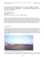
Right: The photo depicts one <strong>of</strong> the known oldest bridges <strong>of</strong> <strong>Bangladesh</strong>. It is a masonry bridge built in the 17th<br />
century during Mughal period over the Mir Kadim Canal, Munshigonj, Dhaka Division. The bridge has a center arch<br />
<strong>of</strong> 4.3m span and 8.5m in height above the bed <strong>of</strong> the canal with two side arches <strong>of</strong>2.2m span each and 5.2m high. The<br />
piers are 1.8m thick. The wings are straight back and the whole length <strong>of</strong> the bridge is 52.7m. Source: Dani, A.H.<br />
(1961). Muslim Architecture in Bengal, Asiatic Society <strong>of</strong> Pakistan Publication No.7, Dacca. Courtesy: Engr.<br />
Emdadul Huq, Retd. Additional Chief Engineer, Public Work Department, <strong>Bangladesh</strong>. Photo: Dr. Engr. A.F.M.<br />
Saiful Amin, BUET.<br />
JSCE~~±*~~<br />
?3APAN SOCIETY OF CNIL ENGINEERS
Barrister Nazmul Huda<br />
Minister<br />
Ministry <strong>of</strong> Communications<br />
Message<br />
It gives me immense pleasure to know that the Civil Engineering Division<br />
<strong>of</strong> the Institution <strong>of</strong> Engineers, <strong>Bangladesh</strong> and the Japan Society <strong>of</strong> Civil<br />
Engineers are jointly organizing a seminar on Advances in Bridge<br />
Engineering in association with the Roads and Highways Department and<br />
Jamuna Multipurpose Bridge Authority.<br />
The adaptation <strong>of</strong> modem technology in the field <strong>of</strong> Bridge Engineering to<br />
keep pace with the developed world is <strong>of</strong> utmost importance. The<br />
participation <strong>of</strong> civil engineers and academicians in the seminar will surely<br />
enhance the quality and standard <strong>of</strong> our bridges. The participation <strong>of</strong> Japan<br />
Society <strong>of</strong> Civil Engineers in this seminar is a milestone for our<br />
technological development and will build a good collaboration between<br />
the engineers <strong>of</strong>the two countries.<br />
I wish Japan-<strong>Bangladesh</strong> Joint Seminar on Advances In Bridge<br />
Engineering a great success.<br />
.;;<br />
JSCE~~±*~~<br />
&-JAPAN SOCIETY OF CIVIL ENGINEERS
Pr<strong>of</strong>essor Jamilur Reza Choudhury<br />
Convenor, Steering Committee<br />
(Past President, Institution <strong>of</strong> Engineers, <strong>Bangladesh</strong>)<br />
Message<br />
I am very happy to note that the Civil Engineering Division <strong>of</strong> the Institution <strong>of</strong><br />
Engineers, <strong>Bangladesh</strong> is organizing a seminar on Advances in Bridge Engineering<br />
jointly with Committee <strong>of</strong> Steel Structures, Japan Society <strong>of</strong> Civil Engineers. This is<br />
for the first time that ajoint Japan-<strong>Bangladesh</strong> seminar is being organized in the field<br />
<strong>of</strong> Bridge Engineering.<br />
The support <strong>of</strong> the two major government agencies involved in construction <strong>of</strong><br />
bridges in <strong>Bangladesh</strong>, viz. Roads and Highways Department and Jamuna<br />
Multipurpose Bridge Authority has helped us a great deal in organzing this seminar.<br />
Recent growth <strong>of</strong> international trade resulting from globalization, coupled with<br />
increasing urbanization, is leading to increasing demands on construction <strong>of</strong><br />
necessary infrastructure. Bridges for highways and railways form an essential<br />
component <strong>of</strong> this infrastructure and are going to play an important role in<br />
accelerating the pace <strong>of</strong> socio-economic development. It is heartening to note that<br />
over the last few years, efforts have been initiated to develop performance-based<br />
model codes which are accepted internationally. The efforts <strong>of</strong> Japanese engineers to<br />
develop such a code are extremely laudable.<br />
In response to our call for papers, a total <strong>of</strong> 14 papers written by the experts in the<br />
broader field <strong>of</strong> Bridge Engineering have been selected for publication in the<br />
proceedings and oral presentation in the Seminar. <strong>Bangladesh</strong>i engineers will benefit<br />
greatly from this seminar where papers dealing with some <strong>of</strong> the latest advances in<br />
steel/composite bridge design and construction are going to be presented and<br />
discussed.<br />
On behalf <strong>of</strong>the Steering Committee, it is my pleasure to welcome all the participants<br />
to the Seminar. I deeply appreciate the hard work <strong>of</strong> the members <strong>of</strong> the organizing<br />
committee in organizing this seminar and am confident that the initiative would lead<br />
to continuing collaboration between Japanese and <strong>Bangladesh</strong>i engineers,<br />
particularly in bridge engineering.<br />
~U--~<br />
Pr<strong>of</strong>essor Jamilur Reza Choudhury<br />
.I.sCE~~±*~~<br />
VJAPAN SOCIETY OF CIVIL ENGINEERS
.---7<br />
4SCEri~±*~~<br />
~~AN SOCIETYOF CIVILENGINEERS<br />
Teruhiko<br />
Yoda<br />
Chair, Committee on Steel Structures<br />
Japan Society <strong>of</strong> Civil Engineers<br />
Message<br />
The Committee on Steel Structures <strong>of</strong> JSCE (Japan Society <strong>of</strong> Civil<br />
Engineers) would like to congratulate the first Japan-<strong>Bangladesh</strong> Joint<br />
Seminar on Advances in Bridge Engineering. We are very happy to be<br />
working with you as a partner on this worthwhile effort. High quality<br />
technical seminars such as this in the Asia-Pacific region are vital for<br />
enhancing international cooperation.<br />
In 2004, a subcommittee was established by the Committee on Steel<br />
Structures to make the Performance-based Design Standards for<br />
SteeVComposite Structures in a limit state philosophy with partial factor<br />
verification, in recognition <strong>of</strong> Asian Model Codes. Clearly, research and<br />
development in this area must rely on the international collaboration with<br />
Asia, Europe and North America. It is hoped that this Joint Seminar would<br />
serve as a platform for improved relations and better cooperation among<br />
the individuals and organizations from <strong>Bangladesh</strong> and Japan.
·~<br />
*~~<br />
~5CEri~±<br />
~PAN SOCIETY OF CIVIL ENGINEERS<br />
Takeshi Mori<br />
Secretary General, Committee on Steel Structure<br />
Japan Society <strong>of</strong> Civil Engineers<br />
Message<br />
Our Society (Japanese Society <strong>of</strong> Civil Engineers, JSCE) has fortunately<br />
made an agreement <strong>of</strong> cooperation with your Institution (The Institution <strong>of</strong><br />
Engineers, <strong>Bangladesh</strong>, IEB) five years ago. However, It is also a fact that<br />
there were not so many opportunities for you and us to contact with each<br />
other in technical issue. I am very pleased and honored to have a chance to<br />
come to <strong>Bangladesh</strong> and organize a seminar with you.<br />
In recent years, every structural engineer in the world recognizes the<br />
importance <strong>of</strong> the international code, and is interested in the code such as<br />
ISO. I hope and trust this meeting will be the first step to make the model<br />
code for bridges accepted in <strong>Bangladesh</strong> and Japan, and to lead to the<br />
Asian code.<br />
• J<br />
JSCE~~±*~~<br />
VJAPAN SOCIETY OF CIVIL ENGINEERS
Pr<strong>of</strong>. Dr. Ing. M. Anwarul Azim<br />
President<br />
The Institution <strong>of</strong> Engineers, <strong>Bangladesh</strong><br />
Message<br />
I am very delighted to learn that for first time the Civil Engineering<br />
Division <strong>of</strong> The Institution <strong>of</strong> Engineers, <strong>Bangladesh</strong> is going to organize a<br />
seminar on bridge Engineering with Japan Society <strong>of</strong> Civil Engineers.<br />
The fate <strong>of</strong>the people will be determined by their technological capability<br />
and flexible knowledge generation and its implementation.<br />
We should be global in our thinking and action. There should be<br />
interactions and co-operation between the engineers with a view to<br />
developing ourselves.<br />
On behalf <strong>of</strong> the Institution <strong>of</strong> Engineers, <strong>Bangladesh</strong> and on my own<br />
behalf, I am conveying my heartful thanks and appreciation to the <strong>of</strong>fice<br />
bearers and all beloved members <strong>of</strong> Civil Engineering Division for taking<br />
the noble endeavors to organize such an important and eventful solemn<br />
occaSIOn.<br />
0~~<br />
Pr<strong>of</strong>. Dr. Ingr. M. Anwarul Azim<br />
•l<br />
..JSCE~~±*~~<br />
~APAN SOCIETY OF CIVIL ENGINEERS
Engr. A.K.M. Faizur Rahman<br />
Chief Engineer<br />
Roads and Highways Department<br />
Message<br />
The importance <strong>of</strong> bridges in developing an uninterrupted communication<br />
network in <strong>Bangladesh</strong> is unquestionable. In this context, we are always<br />
keen to know the technological advances in Bridge engineering in order to<br />
make a sustainable development <strong>of</strong> our communication network with the<br />
optimum uses <strong>of</strong> resources. Furthermore, Japan is a time trusted friend <strong>of</strong><br />
<strong>Bangladesh</strong> and has a long history <strong>of</strong> cooperation in the infrastructure<br />
development <strong>of</strong> our country.<br />
To this end, we are very happy that the Civil Engineering Division <strong>of</strong> the<br />
Institution <strong>of</strong> Engineers, <strong>Bangladesh</strong> has joined its efforts for the first time<br />
with the Japan Society <strong>of</strong> Civil Engineers to organize the seminar on<br />
Advances in Bridge Engineering. The Roads and Highways Department,<br />
Government <strong>of</strong> the Peoples' Republic <strong>of</strong> <strong>Bangladesh</strong> feels very proud and<br />
delighted to be a part <strong>of</strong> the significant event as a co-organizer. In this<br />
regard, it is my pr<strong>of</strong>ound request to all the organizers and participants <strong>of</strong><br />
this occasion tojoin hands together for making it a success in <strong>Bangladesh</strong>.<br />
I am confident that this Seminar will lead to a successful exchange <strong>of</strong><br />
knowledge, transfer <strong>of</strong> technology and share <strong>of</strong> experiences. Also I hope<br />
that the friendship between <strong>Bangladesh</strong> and Japan will increase manifold<br />
through this event. I wish all the delegates from Japan Society <strong>of</strong> Civil<br />
Engineers a great and memorable stay in <strong>Bangladesh</strong>, the land <strong>of</strong> natural<br />
beauty.<br />
Finally, I would like to extend my congratulations and appreciations to the<br />
Civil Engineering Division <strong>of</strong> the Institutions <strong>of</strong> Engineers, <strong>Bangladesh</strong><br />
and the Japan Society <strong>of</strong> Civil Engineers for all the hard working and<br />
earnest effort in making this seminar possible.<br />
•I<br />
J5CEIi~±*~~<br />
t.-'" JAPAN SOCIETY OF CIVIL ENGINEERS
Engr. Md. Nurul Huda<br />
Vice-President (Academic & International Affairs)<br />
The Institution <strong>of</strong> Engineers, <strong>Bangladesh</strong><br />
& Co-Convenor, Steering Committee<br />
Message<br />
I am glad to know that the Civil Engineering Division <strong>of</strong> The Institution <strong>of</strong><br />
Engineers, <strong>Bangladesh</strong> in collaboration with the Roads and Highways<br />
Department and Jamuna Multipurpose Bridge Authority are going to<br />
jointly organize a seminar on Bridge Engineering with Japan Society <strong>of</strong><br />
Civil Engineers on 10August 2005 at Dhaka.<br />
I am confident that this will provide an opportunity to the eminent speakers<br />
to exchange their ideas and experiences for the advancement <strong>of</strong><br />
technologies.<br />
On behalf <strong>of</strong> the Institution <strong>of</strong> Engineers, <strong>Bangladesh</strong> and on my own<br />
behalf, I am conveying my thanks and appreciation to the <strong>of</strong>fice bearers<br />
and all beloved members <strong>of</strong> Civil Engineering Division in taking the noble<br />
endeavors to organize such an important and eventful occasion.<br />
I wish the seminar a great success and convey my good wishes to all the<br />
members <strong>of</strong> Civil Engineering Division. I appreciate Roads and Highways<br />
Department and Jamuna Multipurpose Bridge Authority for their valuable<br />
contribution.<br />
.'7<br />
d5CE!i~±*~~<br />
~PAN SOCIETY OF CIVIL ENGINEERS
Engr. A.N.H. Akhtar Hossain, PEng.<br />
Honorary General Secretary<br />
The Institution <strong>of</strong> Engineers, <strong>Bangladesh</strong><br />
Message<br />
It's a matter <strong>of</strong> immense pleasure to learn that the Civil Engineering<br />
Division <strong>of</strong> The Institution <strong>of</strong> Engineers, <strong>Bangladesh</strong> in collaboration with<br />
the Roads and Highways Department and Jamuna Multipurpose Bridge<br />
Authority is going to jointly organize a seminar on Bridge Engineering<br />
with Japan Society <strong>of</strong> Civil Engineers.<br />
It is again heartening to note that the Civil Engineering Division has been<br />
contributing significantly to the fulfillment <strong>of</strong> the objectives <strong>of</strong> the lEB<br />
since its creation. Holding <strong>of</strong> such a seminar is the testimony <strong>of</strong> their<br />
untiring efforts to uphold the cause <strong>of</strong> the lEB. I hope that the seminar<br />
create an unique opportunity for the members <strong>of</strong> the Civil Engineering<br />
Division to share their experience and knowledge.<br />
I would like to take the opportunity to congratulate the members <strong>of</strong> the<br />
Civil Engineering Division on the eve <strong>of</strong> this event. Further, I would also<br />
like to thank the organizers for their hard work for excellent arrangements .<br />
• 7<br />
aSCE!i~±*~~<br />
JAPAN SOCIETY OF CIVil ENGINEERS
Engr. Md. Rezaul Karim<br />
Chairman, Civil Engineering Division, IEB<br />
& Chairman, Organizing Committee<br />
Message<br />
I consider it is a great privilege to say a few words on the occasion <strong>of</strong>the<br />
seminar Jointly organize by the Japan Society <strong>of</strong> Civil Engineers with<br />
Civil Engineering Division, The Institution <strong>of</strong> Engineers, <strong>Bangladesh</strong><br />
(IEB) in collaboration with the Roads and Highways Department and<br />
Jamuna Multipurpose Bridge Authority.<br />
We are in the new millennium. To meet the challenges <strong>of</strong> the Globalization,<br />
we will have to increase and uphold the pr<strong>of</strong>essional efficiencies. Our<br />
whole approach should be integrated to global development. To attain that<br />
goal the interaction between the pr<strong>of</strong>essionals should be intensified.<br />
I am confident that this seminar will create and opportunity to the Civil<br />
Engineers to Exchange their ideas and experience for advancement <strong>of</strong><br />
technological development in the field <strong>of</strong> Bridge Engineering.<br />
Civil Engineering Division, The Institution <strong>of</strong> Engineers, <strong>Bangladesh</strong> has<br />
been trying relentlessly to improve the pr<strong>of</strong>essional excellence and also<br />
playing an important role for advancement <strong>of</strong>technological development.<br />
I express my gratitude to all the Engineers ,The Executive Committee<br />
members <strong>of</strong> Civil Engineering Division and also to the Engineers <strong>of</strong> the<br />
Roads and Highways Department (RHD) and the <strong>of</strong>ficials <strong>of</strong> Jamuna<br />
Multipurpose Bridge Authority for jointly organize such a seminar. I<br />
would also like to thank Executive Office bearers <strong>of</strong> the Institution <strong>of</strong><br />
Engineers, <strong>Bangladesh</strong> and the various Engineering Organizations for<br />
their advice and co-operation.<br />
cJJ<br />
"<br />
Engr. Md. Rezaul<br />
Karim<br />
j?cE~~±**~<br />
~APAN SOCIETY OF CIVIL ENGINEERS
Engr. Md. Nurul Islam<br />
Secretary, Civil Engineering Division, IEB<br />
The Institution <strong>of</strong> Engineers, <strong>Bangladesh</strong><br />
Message<br />
Civil Engineering Division <strong>of</strong> The Institution <strong>of</strong> Engineers, <strong>Bangladesh</strong> in<br />
collaboration with the Roads and Highways Department and Jamuna<br />
Multipurpose Bridge Authority is going to organize jointly a seminar on<br />
bridge Engineering with Japan Society <strong>of</strong> Civil Engineers on lOth August<br />
2005 at Dhaka with the intention to exchange views, ideas and share<br />
experiences among pr<strong>of</strong>essionals and academicians in the fields <strong>of</strong> Bridge<br />
Engineering.<br />
We are grateful to members and <strong>of</strong>ficials <strong>of</strong> the IEB and the Civil<br />
Engineering Division and also to the Engineers <strong>of</strong> Roads & Highways<br />
Department (RHD) for their wholehearted support and co-operation to<br />
make the program a success. I heartily congratulate the authors from home<br />
and abroad, who took part in presenting their papers in the seminar. I<br />
believe that with their active participation and valuable presentation, the<br />
seminar on Bridge Engineering will be successful. I must pay special<br />
thanks to my divisional committee members & all seminar Committee<br />
Members.<br />
I am thankful to IEB executives, specially Pr<strong>of</strong>. Dr. Ing. M. Anwarul Azim,<br />
President, IEB, Engr. Md. Nurul Huda Vice-president (Academic), IEB,<br />
Engr. A.N.H. Akhtar Hossain, PEng., Honorary General Secretary, IEB,<br />
Pr<strong>of</strong>. Dr. Engr. Jamilur Reza Choudhury, Vice-Chancellor, BRAC<br />
University and Chief Engineer, Roads & Highways Department, for their<br />
kind assistance, co-operation and suggestions.<br />
Finally, I would like to thank Japan Society <strong>of</strong> Civil Engineers, all the Civil<br />
Engineers, members <strong>of</strong> the ElectroniclPrinting Media & the various<br />
Engineering organizations for their advice and co-operation .<br />
•-7<br />
aSCE~~±*~~<br />
~PAN<br />
SOCIETY OF CIVIL ENGINEERS
Civil Engineering Divisional Committee<br />
2004 - 2005<br />
Engr. Md. Rezaul Karim<br />
Chairman<br />
Engr. Md. Salim Bhuiyan<br />
Vice-Chairman<br />
Engr. Md. Nurul Islam<br />
Secretary<br />
Engr. M. A. Kalam<br />
Immediate Past Chairman<br />
Engr. Abdur Rezzaque<br />
Immediate Past secretary<br />
Engr. Matiz Uddin Ahmed<br />
Member<br />
Engr. Md. Asaduzzaman<br />
Member<br />
Khan<br />
Engr. Md. Abdul Azim Joarder<br />
Member<br />
Engr. Md. Lutfor Rahman<br />
Member<br />
Engr. Md. Golam Kibria<br />
Member<br />
.-7<br />
Engr. Md. Shahjahan<br />
Member<br />
J5CEIi~±*~~<br />
VJAPAN SOCIETY OF CIVIL ENGINEERS
Civil Engineering Divisional Committee<br />
2004 - 2005<br />
Engr. Emdadul<br />
Member<br />
Huq<br />
Engr. Md. Rezaul Karim (Reza)<br />
Member<br />
Engr. Md. Yusuf Ali<br />
Member<br />
Engr. Md. Mizanoor<br />
Member<br />
Rahman<br />
Engr. Md. Atikur<br />
Member<br />
Rahman<br />
Dr. Engr. A.F.M. Saiful Amin<br />
Member<br />
Dr. Engr. A.M.M. Safiullah<br />
Member<br />
Engr. Md. Obaidur<br />
Member<br />
Rahman<br />
Engr. Md. Aminur<br />
Member<br />
Rahman<br />
• J<br />
JSCE~~±*~~<br />
~APAN<br />
SOCIETY OF CIVIL ENGINEERS
Pr<strong>of</strong>essor Jamilur Reza Choudhury<br />
Vice-Chancellor, BRAC University<br />
Engr. Md. Nurul Huda<br />
Vice President (Academic & International Affairs)<br />
Institution <strong>of</strong> Engineers, <strong>Bangladesh</strong><br />
Engr. A.K.M. Faizur Rahman<br />
Chief Engineer, Roads and Highways Department<br />
Engr. Alhajj Md. Abdul Malek<br />
Chief Engineer, Jamuna Multi Purpose Bridge Authority<br />
Engr. M. Rezaul Karim<br />
Chairman, Civil Engineering Division, IEB<br />
Pr<strong>of</strong>essor M. Nagai<br />
Nagaoka Institute <strong>of</strong> University<br />
Chair <strong>of</strong> Committee <strong>of</strong> Steel Structures, JSCE<br />
Pr<strong>of</strong>essor E. Yamaguchi<br />
Kyushu Institute <strong>of</strong> Technology &<br />
Secretary, Committee <strong>of</strong> Steel Structures, JSCE<br />
Pr<strong>of</strong>essor H. Yamada<br />
Yokohama National University<br />
Pr<strong>of</strong>essor A.M.M. Safiullah<br />
Department <strong>of</strong> Civil Engineering, BUET<br />
& Member Civil Engineering Division, IEB<br />
Dr. Yoshiaki Okui<br />
Saitama University<br />
Engr. Md. Nurul Islam<br />
Secretary, Civil Engineering Division, IEB<br />
Dr. A.F.M. Saiful Amin<br />
Department <strong>of</strong> Civil Engineering, BUET<br />
& Member Civil Engineering Division, IEB<br />
."'7<br />
-2SCE!:~±*~~<br />
~PAN SOCIETY OF CIVil ENGINEERS
Japan-<strong>Bangladesh</strong><br />
Joint Seminar on Advances in Bridge Engineering<br />
Organizing Committee<br />
Engr. M. Rezaul Karim<br />
Chairman, Civil Engineering Division, IEB<br />
Engr. Md. Nurul Islam<br />
Secretary, Civil Engineering Division, IEB<br />
Engr. Md. Emdadul Hoque<br />
Member, Civil Engineering Division, IEB<br />
Pr<strong>of</strong>essor A.M.M. Safiullah<br />
Department <strong>of</strong> Civil Engineering, BUET.<br />
Engr. Adam Ali Gazi<br />
Additional Chief Engineer<br />
Roads and Highways Department, Sarak Bhaban, Dhaka<br />
Engr. Idrish Miah<br />
Additional Chief Engineer (Technical Services)<br />
Roads and Highways Department<br />
Engr. Mostaq Hossain<br />
Superintending Engineer (Admin & Est)<br />
Roads and Highways Department<br />
Engr. Md. Abdul Azim Joarder<br />
Executive Engineer & Staff Officer to Chief Engineer<br />
Roads and Highways Department<br />
Member, CED, IEB<br />
Engr. M.A. Sobhan<br />
Design Planning and Management Consultants Ltd<br />
House 4/1, Road 4, Dhanmondi RIA, Dhaka 1205<br />
Engr. Zahir Hossain<br />
Managing Director, Mir Akhter Hossain Ltd.<br />
House 13, Road 12, Dhanmondi RIA, Dhaka.<br />
Dr. Engr. Golam Mostafa<br />
Development Design Consultants Limited<br />
47 Mohakhali CIA, Dhaka 1212<br />
Engr. Abdul Aziz<br />
<strong>Bangladesh</strong> Consultants Limited<br />
House 95A, Road 4, Block F, Banani RIA, Dhaka 1213.<br />
Engr. Fauzi Bin Farid<br />
Executive Engineer, PWD<br />
Member, Technical Subcommittee, CED, IEB<br />
Engr. Mizanur Rahman<br />
Member, CED, IEB<br />
Engr. Atiqur Rahman<br />
Member, CED, IEB<br />
Engr. Shahinuzzaman Arun<br />
Dhaka Transport Coordination Board (DTCB)<br />
Nagar Bhaban, 13-14 Floor, Fulbaria, Dhaka.<br />
Dr. A.F.M. Saiful Amin<br />
Department <strong>of</strong> Civil Engineering, BUET.<br />
& Member Civil Engineering Division, IEB.<br />
.7<br />
J5CE~~±*~~<br />
6JAPAN SOCIETY OF CIVIL ENGINEERS
Date: 10 August 2005<br />
Time: 11:00 am-12:15 pm<br />
Chairman: Pr<strong>of</strong>essor Hitoshi Yamada<br />
Co-chairman: Pr<strong>of</strong>essor M. Hossain Ali<br />
A cyclic model for pressure insensitive soil<br />
MR. Hossain, MS.A. Siddiquee, F. Tatsuoka<br />
A nonlinear model for s<strong>of</strong>t rock and its application in bridge pier settlement calculation<br />
MS. Islam, MS.A. Siddiquee, F. Tatsuoka<br />
Geotechnical problems <strong>of</strong> bridge construction in <strong>Bangladesh</strong><br />
A.MM Safiullah<br />
Date: 10 August 2005<br />
Time: 1:15 am-3:l5 pm<br />
Chairman: Pr<strong>of</strong>essor Jamilur Reza Choudhury<br />
Co-chairman: Pr<strong>of</strong>essor Eiki Yamaguchi<br />
Highway bridge specifications and recent development <strong>of</strong> steel-concrete composite bridges in<br />
Japan<br />
Masatsugu Nagai<br />
Numerical model for predicting composite behavior <strong>of</strong> stud shear connectors<br />
Md. Khasro Miah, Akinori Nakqfima, Ahsanul Kabir<br />
Analytical study on steel-concrete composite girders<br />
Yoshiaki Okui<br />
Evaluation method for bending capacity <strong>of</strong> corroded steel girder<br />
TakeshiMori<br />
Scope <strong>of</strong> application <strong>of</strong> composite materials in bridge construction from <strong>Bangladesh</strong> perspective<br />
MA.Sobhan<br />
./<br />
/J5CE~~±*~~<br />
£....0"'" JAPAN SOCIETY Of CML ENGINEERS
Date: 10 August 2005<br />
Time: 3:30 pm-4:45 pm<br />
Chairman: Pr<strong>of</strong>essor Takeshi Mori<br />
Co-chairman: Pr<strong>of</strong>essor A.M.M.T. Anwar<br />
Recent topics in the wind engineering<br />
Hitoshi Yamada<br />
Dynamic behavior <strong>of</strong> cable-stayed bridge with damping<br />
Md. Toihidul Islam, Tanvir Manzur, Alamgir Habib<br />
Vibration serviceability requirement in the design <strong>of</strong> arch-supported suspended footbridge<br />
A.FM Saiful Amin, Tahsin Reza Hossain, Alamgir Habib<br />
Date: 10 August 2005<br />
Time: 5:00 pm-6:15 pm<br />
Chairman: Pr<strong>of</strong>essor A.M.M. Safiullah<br />
Co-chairman: Dr. Yoshiaki Okui<br />
Identification <strong>of</strong> dynamic parameters <strong>of</strong> the Jamuna Multipurpose Bridge in ambient transverse<br />
vibration<br />
R. Ahsan, TM. Al-Hussaini, M.A. Ansary, MM. Rahman<br />
Seismic protective systems for bridges and highway structures in <strong>Bangladesh</strong><br />
AsifIqbal<br />
A method for observing weights <strong>of</strong>trucks running on a bridge<br />
Eiki Yamaguchi, KazushiMatsuo<br />
•l<br />
J5CE~~±*~~<br />
~APAN SOCIETY OF CIVil ENGINEERS
<strong>Bangladesh</strong><br />
SOIneReInarkable<br />
Bridges <strong>of</strong> <strong>Bangladesh</strong>
I am very pleased that Roads and Highways Department (RHD) and Jamuna Multipurpose Bridge<br />
Authority (JMBA) with the joint cooperation from Civil Engineering Division, Institution <strong>of</strong> Engineers,<br />
<strong>Bangladesh</strong> (IEB) and Japan Society <strong>of</strong> Civil Engineers (JSCE) are jointly organizing a seminar on<br />
"Advances in Bridge Engineering" to be held in Dhaka from 1OthAugust to 12th August 2005.<br />
National Land Transport Policy 2004 has called for fostering Inter-National road links for the greater<br />
national interest. Therefore, GOB is relentlessly looking forward to build up regional cooperation to<br />
develop regional and Inter-National road network through proposed Asian Highway.<br />
Roads and Highways Department (RHD) has to manage a total bridge length <strong>of</strong> little more than 184000<br />
meter. For eachkm <strong>of</strong> its 21500 km road network there is a 12 meter bridge. Around 80% <strong>of</strong> the bridges are<br />
in good condition. In order to provide special emphasis on Bridge Maintenance, RHD has created a new<br />
Bridge Management Wing headed by an Additional Chief Engineer. A computerized Bridge/Culvert<br />
Maintenance Management System (BCMMS) have been developed by RHD to facilitate the use <strong>of</strong> Road<br />
Asset Management System (RAMS) to be prepared under World Bank funded Road Sector Reform Project<br />
(RSR-P). At present DFID funded Narrow Bridge replacement project is underway to reconstruct some <strong>of</strong><br />
the nation's narrow and old bridges at different locations within <strong>Bangladesh</strong>. Some <strong>of</strong>the major bridges are<br />
to be constructed in years to come.<br />
This seminar on "Advances in Bridge Engineering" is an opportunity for the Engineers to attain in-depth<br />
knowledge from the Japanese civil engineers who have always been the pioneers in the civil engineering<br />
community with their remarkable structural masterpiece, construction, innovative design and<br />
maintenance approach.<br />
RHD and JMBA have presented technical data on ten <strong>of</strong>their most remarkable bridges. Ibelieve this would<br />
help all attending the seminar to know about the construction methods being used in construction and<br />
maintenance <strong>of</strong> major bridges <strong>of</strong> <strong>Bangladesh</strong>.<br />
I am confident that attendees <strong>of</strong> this seminar will be highly benefited from the deliberations<br />
learned speakers from Japan and <strong>Bangladesh</strong>.<br />
given by the<br />
I convey my heartfelt gratitude to Engr. Md. Ashraful Islam, Superintending Engineer, RHD and all others<br />
in RHD, IEB, JSCE and JMBA who have worked relentlessly to bring success to this prestigious<br />
international seminar.<br />
A.K.M Faizur Rahman<br />
ChiejEngineer<br />
Roads and Highways Department
The development <strong>of</strong> Dhaka-Maw a-Bhang a-Bhatia para- Molla hat- Town Nowapara National Highway has<br />
been built to ensure safe and easy transport <strong>of</strong> South- West region <strong>of</strong> <strong>Bangladesh</strong> with the capital city,<br />
Dhaka under the head line, "South-West Road Network Development Project".<br />
The communication with this road is interrupted by the river, Arial Khan at 9 th km <strong>of</strong> Mawa-Bhanga<br />
section. The construction <strong>of</strong> the bridge is, therefore, very important in connecting divisional head quarter,<br />
Khulna and Barisal, land port, Banapole and river port, Mongla with Dhaka city. The bridge will also<br />
ensure the communication <strong>of</strong> Sundarban, the largest mangrove <strong>of</strong> <strong>Bangladesh</strong> and beautiful sea-beach,<br />
Kuakata with Dhaka city.<br />
The development <strong>of</strong> Dhaka-Mawa-Bhanga-Bhatiapara-<br />
Mollahat-Town Nowapara National Highway has been<br />
implemented under five contracts. The construction <strong>of</strong> this bridge<br />
has been completed successfully under contract No.2. The<br />
Korean construction firm, Hanil Construction Co. Ltd. has<br />
completed the construction <strong>of</strong> the bridge under the supervision <strong>of</strong><br />
consultant, JOC-BCL. The bridge was opened to traffic on 15<br />
May, 2005. The bridge is 450m long and 10m wide. The<br />
superstructure <strong>of</strong> the bridge consists <strong>of</strong> simply supported<br />
prestressed concrete I-girder and in situ RCC slab. The bridge has<br />
10 simply supported spans each 45m long. In designing the<br />
bridge AASTHO live load and specifications have been<br />
followed.<br />
Each Pier and abutment is founded on RCC bored piles. The<br />
foundation <strong>of</strong> the bridge consists <strong>of</strong> 1.0m diameters RCC bored
pile. Each pier consists <strong>of</strong> 16 nos. bored piles <strong>of</strong>length S8m including full-length steel casing <strong>of</strong> 12mm<br />
thickness and the abutment on each side <strong>of</strong> the bridge is founded on 8 nos. bored piles <strong>of</strong> length SOm<br />
including full-length 12mm thick steel casing.<br />
Boring was done under each pier and abutment using bentonite up to full depth <strong>of</strong> piles. Steel casing was<br />
placed in position and mud was cleaned by reverse circulation method. Then pouring <strong>of</strong> grade 30 concrete<br />
was done after placing steel cage.<br />
The decking is supported on RCC piers having two circular columns spaced Sm center to center. A<br />
horizontal tie beam <strong>of</strong> 1m x 1m sizes was introduced at different height from the base.<br />
>-----~--------
Each span comprises 5 nos prestressed concrete girder launched in position by means <strong>of</strong> launching truss<br />
and placed over bearings on piers or abutment. Overall depth <strong>of</strong> each <strong>of</strong> the 5 girders is 2.08m. The web<br />
thickness is 200rnm at center. The flange thickness varies from 2l0rnm to 225rnm at end and center <strong>of</strong><br />
girder. The width <strong>of</strong> top flange is 1.05m and that <strong>of</strong> bottom flange is 700rnm. Each beam consists <strong>of</strong> 9<br />
cables. Prestressing tendon is low relaxation strand with ultimate strength <strong>of</strong> 1870 MPa and confirmed to<br />
the requirements <strong>of</strong> ASTM-A 416-85 or equivalent. Stiffening diaphragms have been provided in each<br />
span at 11.lm intervals.
The flow <strong>of</strong> the river Arial khan is very unpredictable. The direction <strong>of</strong> the river flow changes every year<br />
during monsoon. Moreover, geography and morphology <strong>of</strong> the river changes take place during devastating<br />
flood. Due to this reason, the mathematical model study has been performed to determine the movement <strong>of</strong><br />
the river and the intensity <strong>of</strong> scour. The physical Model study <strong>of</strong> the river has also been done. Based on the<br />
above study result river training works have been done and guide bund has been constructed.
Bagerhat district town stands on the river Bhairab. Khulna-Bagerhat-Perojpur Regional Highway (R770)<br />
crosses this river at Bagerhat. Two divisional towns Khulna and Barisal are connected through this<br />
highway. Prior to construction <strong>of</strong> this bridge the road communication was being maintained by RHD<br />
ferries. Construction <strong>of</strong> Doratana bridge over the river Bhairab was a long waiting demand and widely felt<br />
need <strong>of</strong> the people <strong>of</strong> these areas. The construction <strong>of</strong> bridge over the river gap is not only <strong>of</strong> strategic<br />
importance in the national highway network, but regionally its construction facilitates the movement <strong>of</strong><br />
people, resources and products between the central and south-west areas <strong>of</strong> <strong>Bangladesh</strong>. It facilitates the<br />
smooth movement <strong>of</strong> people to the Majar <strong>of</strong> Khan Jahan Ali (R) located at Bagerhat. Tourists are also<br />
enjoying unhindered road communication to visit historical Sat Gumboj Mosque.<br />
The bridge is located over the river Bhairab near Bagerhat district town at 2 nd<br />
road.<br />
km <strong>of</strong> Bagerhat-Perojpur<br />
The bridge is funded entirely by internal resources and designed<br />
by Roads and Highways Department. The Executing Agency was<br />
Roads and Highways Department, Ministry <strong>of</strong> Communications.<br />
The bridge was constructed by local construction firm, AI-Amin<br />
Construction Co. Ltd. The bridge was opened to traffic on 28 June<br />
2003.<br />
The bridge is 630.50 m long and 10m wide (carriageway 7.5m and<br />
2xI.25m sidewalk). It consists <strong>of</strong> 13 spans <strong>of</strong> 48.5m each. The<br />
bridge has been designed for two lanes following AASTHO<br />
HS20-44 loading.
3':'oSTIWGHTGl'.A:lIDft 5%""U.1llU' t 1I01)%UllllOO', 5·~nU8Cl.lt 3%STR.l1QIT "~OI;:Jrf<br />
~ I T "'''''' __ ~ ~<br />
I "'" I """I"".'<br />
I<br />
ru.e.aa...<br />
",'"<br />
I...~.....<br />
The preliminary design and drawing <strong>of</strong> Doratana bridge was sent to the field unit <strong>of</strong> RHD for taking<br />
necessary action for construction <strong>of</strong> the bridge. While sending the drawings to the field unit, the design unit<br />
<strong>of</strong>RHD provided notes on the drawings stating that a) the construction <strong>of</strong> the bridge can be taken up by<br />
checking the design and drawings by experienced consultant and b) provision shall have to be made in the<br />
tender document for checking and reviewing the design and drawing by experienced consultant for<br />
construction <strong>of</strong> the bridge.<br />
Accordingly the field unit <strong>of</strong>RHD invited tenders providing the above conditions set by the design unit.<br />
According to the conditions <strong>of</strong> contract document, the selected contractor for construction <strong>of</strong> the bridge<br />
engaged Design Planning and Management Consultant for reviewing the design <strong>of</strong> foundation and<br />
substructure <strong>of</strong>the bridge and BRTC, BUET for checking the superstructure. BRTC, BUET reviewed the<br />
design <strong>of</strong> superstructure.<br />
According to the preliminary design and drawing this bridge consists <strong>of</strong> 13-span simply-supported PC<br />
girder bridge having equal spans, each 48.5m long between c/c piers, and the end spans are each 48.5m<br />
between c/c pier and the center line <strong>of</strong> the movement joint over the abutment giving a total length <strong>of</strong><br />
630.50m. The bridge superstructure comprises 7.5m wide carriageway and 10m out to out width <strong>of</strong> deck<br />
including two sidewalks. The deck is supported over 5 nos. prestressed concrete girders placed at 2.0m<br />
intervals. The substructure piers are RCC wall type having 1.5m width x 5.5m length.<br />
The six intermediate pier foundations comprise 1O.Omx 5.5m size x 31.5m long RCC caissons. The<br />
remaining pier foundations contain 36 nos. 0.35m x 0.35m size x 28.0m long precast RCC piles for each<br />
pier. Abutments are RCC wall type having flag type wing walls. Each abutment foundation comprises 40<br />
No. 0.35m x .35m size x28m long precast RCC piles. The main navigational span contains 43.0m<br />
horizontal navigational clearance between the adjacent wells and ll.945m vertical navigational clearance<br />
above the high water level upto the girder s<strong>of</strong>fit.
i) The length <strong>of</strong> the PC girder for this bridge is 48.470m. This is the maximum length <strong>of</strong> pre-cast 1-<br />
girder or T-girder constructed using the launching girder available in the country. Besides the cast<br />
in -situ construction <strong>of</strong> such a large size girder using shoring embedded in the s<strong>of</strong>t bed material at<br />
the bridge site has risks <strong>of</strong>formwork settlement. It is therefore considered advisable to select such<br />
structural option and construction methodology <strong>of</strong> the foundations whereby the possibility <strong>of</strong><br />
increase in the span length due to tilt and shift <strong>of</strong> the foundations could be minimized.<br />
ii) The sub soil investigation conducted adjacent to the pier locations shows s<strong>of</strong>t to firm, firm to stiff<br />
soil having SPT values between 4 and 7 up to about 14m depth below the existing bed level. The<br />
harder strata is encountered below. From design point <strong>of</strong> view, well is an ideal structural option in<br />
such soil. However, from the construction point <strong>of</strong> view the existence <strong>of</strong> the s<strong>of</strong>t soil in the top<br />
strata increase the risks <strong>of</strong> tilt and shift <strong>of</strong> the well. The usual method <strong>of</strong> construction involves<br />
developing an artificial island with its top at about the normal high water level. The construction<br />
<strong>of</strong> well will be made from that platform. The contract design shows the top <strong>of</strong> well cap at EI O.OOm<br />
PWD whereas the natural bed level around the pier is at about El. -7.00 to -7 .50m PWD in deep<br />
water. This gives the unsupported height <strong>of</strong> well above the river bed level about 7.00 to 7.50m.<br />
The artificial island <strong>of</strong> this height supported on the s<strong>of</strong>t soil is likely to incur considerable vertical<br />
settlement. Further, the required embedment length <strong>of</strong>the peripheral tubular supports sustaining<br />
the lateral earth pressure for this height <strong>of</strong> backfill will also considerable.<br />
iii) The three years construction period is likely to provide maximum two working seasons for<br />
construction <strong>of</strong> all the six wells, otherwise completion <strong>of</strong> the work within the contract period<br />
might be difficult. The harder strata underlying the top s<strong>of</strong>t strata is again likely to reduce the rate<br />
<strong>of</strong> penetration <strong>of</strong> the wells considerably. The sinking <strong>of</strong> the 31.5m length <strong>of</strong> well might even<br />
consume the whole <strong>of</strong> the available three working seasons. This means even if all the six wells are<br />
started at one time, the completion <strong>of</strong> wells themselves might consume the entire contract period,<br />
due to the field subsoil conditions.<br />
iv) This will necessitate maintaining the wells during the three flood seasons. The six rectangular<br />
shaped islands with semi-circular noses inside river, having plan size <strong>of</strong> about 20.00m width x<br />
30.00m length is likely to constrict the passageway <strong>of</strong>the flood water, and thereby enhancing the<br />
local scour around the island considerably. The observed maximum scour depth at that case might<br />
exceed the design value. If the construction is further delayed, this constriction <strong>of</strong> the water way<br />
might affect the morphology or the regime <strong>of</strong> the river permanently.<br />
v) Further, although from the structural point <strong>of</strong> view the steining thickness <strong>of</strong> the designed RCC<br />
caisson is found adequate, it might not be found adequate from the construction point <strong>of</strong> view. To<br />
facilitate sinking <strong>of</strong> caisson in the hard strata needs overcoming the skin friction on the surface <strong>of</strong><br />
the well. The relevant Indian Road Congress (lRC) code recommends about double steining<br />
thickness than provided in the contract drawings from construction point <strong>of</strong> view, which<br />
increases cost. In addition, sinking <strong>of</strong> well will need further kentledge arrangement.<br />
vi)<br />
The other pier and abutment foundations comprising 0.35 m x 0.35m size x28.00m long precast<br />
piles may also generate difficulties in construction in the lower hard strata. The long precast<br />
slender piles might require to be driven in two pieces. This will require normally expensive<br />
patented moment splicing, for example, Hercules splicing or equivalent, which is difficult to be<br />
mobilized for this local currency project.<br />
An alternative design replacing the caisson/precast pile foundations below piers/abutments, by 1/0.76mdia<br />
cast in-situ bored pile foundations for both abutments and piers are proposed. This, compared to the
caisson foundation, has an advantage that its tilt and shift is easier to control and its construction<br />
be faster without sacrificing the quality.<br />
is likely to<br />
The wall type piers have been replaced by the column type piers to reduce cost without<br />
durability <strong>of</strong>the structure.<br />
affecting the<br />
Taking the comments made by the consultants into consideration, final design and drawing was approved<br />
by RHD and sent to the field unit for its implementation.<br />
The bridge consists <strong>of</strong> 12 piers and two abutments. Each pier and abutment is founded on RCC bored pile.<br />
Four piers are provided in the river in which 2 <strong>of</strong> these comprises 12 No.bored piles <strong>of</strong> 1m diameter, each<br />
35m long with 10mm thick 20m long permanent steel casing at top and other 2 comprises 12 No. bored<br />
piles <strong>of</strong> 1m diameters, each 32m long with 10mm thick 15m long permanent steel casing. Two bank piers<br />
comprise 10 nos. bored piles <strong>of</strong> 1m diameter, each 32m long with 10mm thick 5m long permanent steel<br />
casing. The rest six piers comprise 10 nos. bored piles <strong>of</strong>O.76m diameters, each 30m long. The Bagerhat<br />
side abutment consists <strong>of</strong> 20 nos. bored piles <strong>of</strong> 0.76m diameter, each 27m long and the Perojpur side<br />
abutment consists <strong>of</strong>20 No.bored piles <strong>of</strong>O.76m diameters, each 25m long.<br />
Boring was done under each pier and abutment using bentonite upto full depth <strong>of</strong> piles. Mud was cleaned<br />
properly. Then pouring <strong>of</strong> concrete was done after placing steel cage.<br />
The decking is supported on RCC piers having two circular columns spaced 5m centre to centre. A<br />
horizontal tie beam <strong>of</strong> 1m x o.75m sizes was introduced at different height from the base.<br />
,,<br />
I<br />
- ------r-- ------<br />
T)l~l~r, J---;-r~Ji<br />
-{_~_~<br />
-{_J._'<br />
'..:., ../ I , ...~...'<br />
luz=. 18<br />
., rIfe<br />
PII;R PILE CAP PLAN - REINF. DETAil"<br />
Each span comprises 5 No. Prestressed post-tensioned concrete girder and placed over elastomeric<br />
bearings on piers or abutment. Overall depth <strong>of</strong> each <strong>of</strong> the 5 girders is 2.6m. The web thickness is 240mm<br />
at center <strong>of</strong>the girder. The flange thickness is 175mm at end and center <strong>of</strong> girder. The width <strong>of</strong> top flange is<br />
1.lm and that <strong>of</strong> bottom flange is 740mm. Each beam consists <strong>of</strong> 12 tendons and each tendon consists <strong>of</strong>6<br />
No (7 wires) strands <strong>of</strong> 12.7 mm diameter. Prestressing tendon is normal relaxation strand with breaking<br />
strength <strong>of</strong> each strand not less than 183.5 KN conformed to ASTM A 416-85 or approved equivalent.<br />
Cylinder crushing strength <strong>of</strong> prestressed girder is 35 MPa at 28 days and crushing strength <strong>of</strong> concrete at<br />
time <strong>of</strong> transfer <strong>of</strong> prestressing force is 28 MPa (Minimum).
10000<br />
7500<br />
01<br />
:£1<br />
1<br />
I<br />
l
Kurigram is a district <strong>of</strong>rivers. The big rivers like Brahmaputra, Dharala, Tista and other narrow rivers<br />
flow through this district. Dharala is a meandering river. It changes its course frequently. Nageshwari,<br />
Bhurungamari and Fulbari upazillas are situated in the north side <strong>of</strong> this river. In the absence <strong>of</strong> a bridge<br />
over this gap, these upazillas were isolated from direct road communication with the Head Quarter <strong>of</strong><br />
Kurigram district and also other parts <strong>of</strong> the country. Prior to construction <strong>of</strong> this bridge, the road<br />
communication was being maintained by RHD ferries. The people <strong>of</strong> these three upazillas suffered much<br />
particularly in the monsoon when the river became widened and tremendous water flow suspended the<br />
ferry services. So constructing a bridge over the river Dharala was a long waiting demand and widely felt<br />
need <strong>of</strong>the people <strong>of</strong>these areas.<br />
The bridge is located over the river Dharala near Kurigram district town at 3'd km <strong>of</strong> Kurigram-<br />
Nageshwari-Bhurungamari road (Z5622).<br />
The preliminary study for construction <strong>of</strong> Dharala bridge was conducted by Rajshahi Division<br />
Development Board in 1978. With the passage <strong>of</strong> time, record shows that Dharala river is very much<br />
meandering in nature and changes its course frequently. This river is found very much unstable and hits the<br />
embankment on both sides and <strong>of</strong>ten develops char area due to huge siltation. Even Kurigram district town<br />
was threatened several times. The Water Development Board (WDB), <strong>Bangladesh</strong> had to make protection<br />
embankment with several heavy groynes to save Kurigram town. So to select a suitable alignment and<br />
required river training works it was necessary to conduct hydrological study, physical modeling, sub-soil<br />
investigation and detailed design <strong>of</strong>the bridge through consultant.
Kurigram is a district <strong>of</strong> rivers. The big rivers like Brahmaputra, Dharala, Tista and other narrow rivers<br />
flow through this district. Dharala is a meandering river. It changes its course frequently. Nageshwari,<br />
Bhurungamari and Fulbari upazillas are situated in the north side <strong>of</strong> this river. In the absence <strong>of</strong> a bridge<br />
over this gap, these upazillas were isolated from direct road communication with the Head Quarter <strong>of</strong><br />
Kurigram district and also other parts <strong>of</strong> the country. Prior to construction <strong>of</strong> this bridge, the road<br />
communication was being maintained by RHD ferries. The people <strong>of</strong> these three upazillas suffered much<br />
particularly in the monsoon when the river became widened and tremendous water flow suspended the<br />
ferry services. So constructing a bridge over the river Dharala was a long waiting demand and widely felt<br />
need <strong>of</strong>the people <strong>of</strong> these areas.<br />
The bridge is located over the river Dharala near Kurigram district town at 3'd km <strong>of</strong> Kurigram-<br />
Nageshwari-Bhurungamari road (Z5622).<br />
The preliminary study for construction <strong>of</strong> Dharala bridge was conducted by Rajshahi Division<br />
Development Board in 1978. With the passage <strong>of</strong> time, record shows that Dharala river is very much<br />
meandering in nature and changes its course frequently. This river isfound very much unstable and hits the<br />
embankment on both sides and <strong>of</strong>ten develops char area due tohuge siltation. Even Kurigram district town<br />
was threatened several times. The Water Development Board (WDB), <strong>Bangladesh</strong> had to make protection<br />
embankment with several heavy groynes to save Kurigram town. So to select a suitable alignment and<br />
required river training works it was necessary to conduct hydrological study, physical modeling, sub-soil<br />
investigation and detailed design <strong>of</strong>the bridge through consultant.
I ---------------10.000------------------11<br />
~-----~~'02&<br />
~m$o_--~I<br />
20._ 100 CIC<br />
1&••<br />
IIlO'ciClbj<br />
",,- . .<br />
'-- IO.~6IXl C.c<br />
SECTION<br />
SCOI.--.---<br />
r 2OU~ 100 CIC<br />
..-....•<br />
I<br />
eoo-j<br />
, ~:.. ,.: ~'-,,1-'" .<br />
. )' •• ;llllC~lbl<br />
.I··~-llji~';: .<br />
-.:...I'<br />
x.<br />
::.: .:~.~~. :<br />
.'t:-.:'{<br />
.:~~,,:~~: ..<br />
.......~:"'="~~ .:;#.~ .rf<br />
r- :t ..;>~(<br />
I<br />
L 20.0100<br />
CiC<br />
--:..,...<br />
..."
The decking is supported on16 Nos RCC wall type piers founded on 16 Nos RCC caissons. The thickness<br />
<strong>of</strong> wall type pier is 1.5m and length is 5.5 m. The size <strong>of</strong> pier cap is 2.0m x 1.75m. The height <strong>of</strong> piers varies<br />
from 5.04m to 11.37m. depending on the longitudinal gradient <strong>of</strong> bridge.<br />
:11,...-· ...•••<br />
V \/ R 6\<br />
1·1" . \ ,.<br />
, If;<br />
PIGl<br />
t-y'!"-v'<br />
I '<br />
\ \<br />
\ \<br />
The bridge has 15 spans each 43.18 m long supported on 16 RCC caissons. Each span comprises<br />
prestressed post-tensioned girders and placed over elastomeric bearings on piers.<br />
5 nos.<br />
-'--'--~-'~I<br />
~1:
Overall depth <strong>of</strong> each <strong>of</strong> 5 PC girder is 2.3m for bridge. The web thickness is 200mm at center. The flange<br />
thickness is 130mm. Width <strong>of</strong> top flange is 1060mm and that <strong>of</strong> bottom is 71Omm. Each beam consists <strong>of</strong><br />
12 tendons and each tendon consists <strong>of</strong>6 No (7 wires) strands <strong>of</strong> 12.7mm diameter. Prestressing tendon is<br />
low relaxation strand with breaking strength <strong>of</strong> each strand not less than 160.1 kN conformed to AASTHO<br />
M-203 cylinder crushing strength <strong>of</strong> prestressed girder is 35 MPa at 28 days and crushing strength <strong>of</strong><br />
concrete at time <strong>of</strong> transfer <strong>of</strong> prestressing force is 28 MPa (Minimum).<br />
Six RCC cross girders are used between the PC girders at six places. First cross girder is placed 250mm<br />
from each end <strong>of</strong> the PC beam. Second cross girder is placed at a distance <strong>of</strong>9.484m from first cross girder<br />
and the rests are placed at 7.904m intervals. The width <strong>of</strong> each cross girder is 300mm and the depth is<br />
1.85m.<br />
Reinforcing bars (except prestressing tendon) are high tensile deformed bars having minimum yield<br />
strength <strong>of</strong> 415 MPa conforming to ASTM A 615M /A616M/ A706.<br />
At the site <strong>of</strong> the bridge the river flows over a large width and during high floods it has the tendency to<br />
overflow the banks on Pateshwari side. To restrict the river width and to prevent the overflow <strong>of</strong> water<br />
guide bank has been provided on Pateshwari side. The length <strong>of</strong> the guide bank is 1.027 km. The waterside<br />
<strong>of</strong> the guide bank has been provided with cement concrete pitching laid in blocks in two layers (first layer<br />
450mm x 450mm x300mm and 2nd layer 380mm x 380mm x 300mm) over a layer <strong>of</strong> 200mm thick<br />
shingles and pea gravels (60mm-40mm and 30mm-lOmm). Geotextile is placed between the layer <strong>of</strong><br />
singles, pea gravels and 100mm thick sand layer over compacted earth. The slope <strong>of</strong> the guide bank at<br />
riverside is maintained 2H: 1V removing all bank irregularities. The width <strong>of</strong> the guide bank at top is 4m.<br />
The compressive strength <strong>of</strong> concrete for making blocks is 15MPa at 28 days according to ASTM C39. 12<br />
m-28.5m wide apron consists <strong>of</strong>layers <strong>of</strong> graded stone having a depth <strong>of</strong> 2m.<br />
Generally settlement <strong>of</strong> backfilling takes place behind the abutment wall (between abutment wall and<br />
approach road) if its compaction is not done properly which causes hindrance to the smooth plying <strong>of</strong><br />
vehicle. To avoid this problem a approach slab <strong>of</strong>5m long has been provided at both ends <strong>of</strong> the bridge.<br />
Approach Road<br />
The bridge includes approach roads <strong>of</strong> length 1.92km at kurigram side and 1.42 km at pateswari side. The<br />
width <strong>of</strong>the approach road 11meter including 6.7 m carriageway and 2.15m shoulders on each side.<br />
Total cost <strong>of</strong> the bridge was Taka 97.50 Crore, which was borne entirely by the Government<br />
<strong>Bangladesh</strong>.<br />
<strong>of</strong>
The Dhaka-Chittagong highway is the most vital link between Dhaka, the capital <strong>of</strong> <strong>Bangladesh</strong>, and<br />
Chittagong, the international port city. The 257 km long Dhaka-Chittagong National Highway (N I) a part<br />
<strong>of</strong> Asian Highway, serves a population <strong>of</strong> about 15 million <strong>of</strong> the region. The Highway carries the heaviest<br />
traffic in the country in spite <strong>of</strong>the inconveniences and delays in road transportation caused by two ferries<br />
at Meghna and Meghna-Gumti Rivers. The necessity for constructing Meghna and Meghna-Gumti<br />
Bridges was to remove the bottle-necks at the ferries, leading to increase economic activity between the<br />
two major cities <strong>of</strong> <strong>Bangladesh</strong>.<br />
By the completion <strong>of</strong> the two Bridges, Dhaka and Chitta gong are connected entirely by highway. Travel ing<br />
time between the two cities is three hours shorter than using ferry crossings. Now people are visiting each<br />
other within a day. Meghna Bridge is deemed as a symbol <strong>of</strong> friendship between <strong>Bangladesh</strong> and Japan,<br />
and is known as "Japan-<strong>Bangladesh</strong> Friendship Bridge".<br />
)"'j)<br />
.: ..:\\<br />
.<br />
The bridge consists <strong>of</strong> 13 spans <strong>of</strong>9 spans each 87m, 2 spans each 48.5m and 2 spans each 25m giving a<br />
total length <strong>of</strong> 930m. Total width <strong>of</strong> the bridge is 9.2m including sidewalk and railing. The Executing<br />
Agency was Roads and Highways Department, Ministry <strong>of</strong> Communications, Government <strong>of</strong>the Peoples'<br />
Republic <strong>of</strong> <strong>Bangladesh</strong>. The consultant was Pacific Consultants International, Japan in association with<br />
Nippon Koei Co. Ltd, Japan and the Contractor was Obayashi Corporation, Japan. The bridge was<br />
Constructed by Japanese Grant Aid. The bridge was designed following AASTHO HS 20-44 loading. The<br />
bridge was opened to traffic on February 1991. Meghna Bridge was awarded "Outstanding Achievement<br />
Award, JSCE in 1994".
~ I: HAl """IN<br />
II'( • ,.I11j<br />
•.. •<br />
...<br />
Typlc:al<br />
en... __<br />
I~<br />
I<br />
~i.<br />
... ...•.<br />
I<br />
,"1<br />
'!
The substructure comprises cast insitu concrete piles and piers which were constructed in the river Meghna<br />
at the time <strong>of</strong> receding flood water. High water level and high stream current velocity <strong>of</strong> the River occurs in<br />
rainy season. Two dry seasons were necessary to complete these substructures consisting <strong>of</strong> 12 piers and 2<br />
abutments.<br />
The construction <strong>of</strong>the superstructure, comprising segmental PC-box girders, was carried out through out<br />
the whole year even in rainy season.<br />
It must be mentioned that the successful completion <strong>of</strong> the construction <strong>of</strong> c<strong>of</strong>ferdams for the substructure<br />
made a great contribution towards the completion <strong>of</strong> the whole <strong>of</strong>the construction works.<br />
1) With steel pipe piles (diameter: 1.016 m, length: 28.5 m) with vertical interlocking system for 8 piers<br />
from pier P-2 to P-9. The c<strong>of</strong>ferdam constructed with steel pipe piles <strong>of</strong>P-2 was constantly watched<br />
by means <strong>of</strong> strain-stress measuring gauge for ensuring safety.<br />
2) With steel sheet piles (type VL) for 2 piers (P-l and P-I0) and2 abutments.<br />
3) With steel sheet piles type V for 2 piers (P-ll and P-12).<br />
106 cast-in-situ concrete piles <strong>of</strong> 1.5m in diameter were constructed by using reverse circulation drilling<br />
method. A supersonic measuring system was adopted for the vertical accuracy <strong>of</strong> the bore holes. The<br />
lengths <strong>of</strong> these piles are variable ranging from 40.0 m to 58.0 mdepending onthe level <strong>of</strong>the bearing strata<br />
for the piles.<br />
The length <strong>of</strong> pile cap is II m in longitudinal direction and in transverse direction also. Pile cap concrete<br />
was poured on cast-in-situ by tremie pipe from the mixing plant directly. The thickness <strong>of</strong> pile cap is 2.7 m<br />
at the center and 2.2 m at the edge. The RL level <strong>of</strong>the lower surface <strong>of</strong> the pile cap is -9.5 m.<br />
Scour protection above the pile caps in the river was carried out by boulder pitching from floating vessels.<br />
The volume <strong>of</strong> the works done was 18,800 m 3 .
The pier column has a hexagonal shape and each pier from pier (P-4 to P-7) was constructed in five<br />
operations but other piers in three or four operations. The time <strong>of</strong> operation was dependent on the height <strong>of</strong><br />
piers which varied from 10.433m to29.144 m. Piers <strong>of</strong>P-ll andP-12 were constructed on the shore.<br />
I J<br />
L Q<br />
$WlZI..l.;.L.<br />
u" .• ~<br />
• ,~.~(0t4<br />
UTI<br />
XWl!U:J..
10 segments <strong>of</strong> PC-box girder at both side <strong>of</strong> each pier. column top were constructed successively by using<br />
traveling forms.<br />
This type <strong>of</strong> construction system is called the cantilever erection method. The depth <strong>of</strong> PC-box girder<br />
gradually varies from about 5.3 matsegmentNo.l and NO.2 to 1.9m atsegmentNo.19 andNo.20. The PC<br />
tendons were inserted into sheath duct provided in the box girder webs and upper deck slab. PC bars at an<br />
interval <strong>of</strong> 0.6 m to 1.6 m were installed in every segment. The number <strong>of</strong> PC tendons was reduced at the<br />
end <strong>of</strong> every segment. Total 200 segments <strong>of</strong> PC- box girders were constructed for the ten piers.<br />
l AU" •<br />
FW:-:·~' ".'
River revetment works are the main ancillary works for the protection <strong>of</strong> river bank from erosion. These<br />
works consisted <strong>of</strong> geo-textile form concrete mat, capping concrete and placing boulder gabions in front <strong>of</strong><br />
the revetments. River revetment works on Comilla side were constructed after deep consideration <strong>of</strong><br />
further erosion <strong>of</strong>the river bank. Geo-textile form concrete mat, the first application in <strong>Bangladesh</strong>, is used<br />
as well as the concrete mat. The total quantity <strong>of</strong> work done was 657 linear meters out <strong>of</strong> which 148 m were<br />
on Dhaka side and 509m on Comilla side.<br />
After the completion <strong>of</strong> the Bridge, additional revetment works were carried out in 1994 and 1998, by<br />
additional Japanese Grant Aid.
The communication between Dhaka city and South-West part <strong>of</strong> <strong>Bangladesh</strong> is interrupted by the river<br />
Buriganga. The construction <strong>of</strong> <strong>Bangladesh</strong>-China Friendship bridge were helping to reduce the<br />
hindrance in part but a necessity <strong>of</strong> building a second bridge over the river Buriganga was felt. Before the<br />
2nd Buriganga bridge was constructed, road traffic crossed the river by ferry, <strong>of</strong>ten subject to considerable<br />
delay due to traffic problems or river conditions. The construction <strong>of</strong> Bridge over the river Buriganga is<br />
therefore <strong>of</strong> strategic importance in the national highway network. Its construction facilitated the<br />
movement <strong>of</strong> people, resources and products between the capital city Dhaka and Karanigonj- Dhohar areas<br />
<strong>of</strong> <strong>Bangladesh</strong><br />
This Bridge is located about 3 km away from the city centre in the south over the river Burigonga which<br />
connects Babubazar and Jinjira. The bridge provides an essential road connection across the river<br />
Buriganga in Dhaka city. In addition to providing a fixed crossing close to the city center, it <strong>of</strong>fers more<br />
direct access from the old Dhaka town to Dhaka- Khulna Road (N8). It connected not only Babu bazar to<br />
Jingira but also connected Keranigonj-Dhohar in the West and Dhaka-Mawa- Khulna National Highway<br />
in the East by constructing approach road.
The bridge carries a 4-lane roadway and two 1.5m wide sidewalks on its l4.6m wide deck. The structure is<br />
l479m long which includes six river spans totaling 304m in length and shore viaducts and access ramps at<br />
each end. Bored cast in-place RCC piles are provided at each pier location. Total length <strong>of</strong>the flyover is 712<br />
meter and that <strong>of</strong> approach ramp is 463 meter.<br />
No fixed crossing had existed until the first Buriganga bridge, known as <strong>Bangladesh</strong>-China Friendship<br />
Bridge, was opened to traffic in 1990. The bridge, however, was built primarily to serve the Dhaka-Khulna<br />
Road. Being located about 3km downstream from the business district, it did not assist in city's expansion<br />
across the river or improve communication to the right bank areas with the Metropolis.<br />
Sponsoring agency <strong>of</strong> the bridge was the Roads and Railways Division, Ministry <strong>of</strong> Communications<br />
(MOC), People's Republic <strong>of</strong> <strong>Bangladesh</strong>. Roads and Highways Department was the executing agency.<br />
International bids were invited in 1993 for a Design- Build contract. The Engineers Ltd, a local construction<br />
firm, was the successful bidder. Government <strong>of</strong> <strong>Bangladesh</strong> appointed <strong>Bangladesh</strong> Consultants Ltd. as the<br />
Design Check and Supervision Consultant in June 1994 for the bridge. The work commenced in August<br />
1994.
Navigational clearance <strong>of</strong> main bridge is 45.73m. (horizontal) and 7.62m (vertical) above Standard High<br />
Water Level. The bridge has been designed following AASHTO HS 20-44 loading The bridge was<br />
opened to traffic on 20 May 200 I.<br />
The bridge was funded entirely by internal resources. The design and construction <strong>of</strong> the bridge were done<br />
successfully by using indigenous expertise and technology which is a great example for the engineers <strong>of</strong><br />
the future generation.<br />
Six river spans were founded on RCC caissons while the shore structures on cast in-situ RCC pile. The<br />
foundation <strong>of</strong> main bridge consists <strong>of</strong>5 Nos RCC caissons (size:6mxI3Am). Its wall thickness varies from<br />
0.50m to O.70m depending on the depth <strong>of</strong> well from riverbed level. The well curbs are 700mm thick and<br />
2500mm deep. 18mm diameter OAm long anchor bars spaced 300mm centre to centre (staggered) was<br />
welded to 750mmx3mm M.S plate for mid wall <strong>of</strong> caisson and for the rest portion, anchor bars welded to<br />
950mm x 3mm M.S plate. The caissons were sunk by open dredging making use <strong>of</strong>kentledge as and when<br />
required. Grabs were used during sinking operation. 3 cassions, each 34.5 m long in deep water and 2<br />
cassions each <strong>of</strong>length 32.5m on both banks were constructed.<br />
The fly over <strong>of</strong> length 343m at Dhaka end and 369 m at Jinjira end were constructed over 25 Nos. piers.<br />
Piers were founded on 324 Nos. cast in situ RCC piles and abutment at each side contains 18 cast in -situ<br />
piles. 750mm diameter cast in situ RCC piles were used under piers and abutments. Boring was done under<br />
each pier and abutment using bentonite upto full depth <strong>of</strong> piles. Mud was cleaned and pouring <strong>of</strong> concrete<br />
was done after placing steel cage.<br />
The number and length <strong>of</strong> cast in situ RCC piles under piers and abutments are shown in the following<br />
table.
Namc <strong>of</strong> Dhaka cnd Jinjira cnd<br />
Structure<br />
Number Number Length <strong>of</strong> Number Number Length <strong>of</strong> each<br />
<strong>of</strong> piles cach pilc(m) <strong>of</strong>pilcs pile(m)<br />
Abutment 18 20 18 22<br />
Pier 12 156 20 13 168 22<br />
The decking is supported on 25 nos RCC wall type piers founded on 324 nos. cast in -situ RCC piles for<br />
flyovers and the decking <strong>of</strong> main bridge is supported on 5 RCC Wall type Y-piers founded on 5 nos. RCC<br />
caissons. The bridge consists <strong>of</strong> two RCC abutments for both sides founded on 36 nos cast in-situ RCC<br />
piles.
The main bridge has 6 spans each 44m long having 5 RCC Y-frames each <strong>of</strong> length 8m giving a total<br />
length <strong>of</strong> 304 m supported on five RCC caissons. Each span <strong>of</strong> the main bridge comprises 9 nos.<br />
prestressed post-tensioned girders launched in position by means <strong>of</strong> launching truss and placed over<br />
elastromeric bearings on piers. Overall depth <strong>of</strong> each <strong>of</strong>9 P.C girder is 2.21 Omfor the main bridge.<br />
The web thickness is 220mm at center. The flange thickness is 150mm. Width <strong>of</strong> top flange is 1090mm and<br />
that <strong>of</strong> bottom is nOmm. Each beam consists <strong>of</strong> 10 tendons and each tendon consists <strong>of</strong> 6 No (7 wires)<br />
strands <strong>of</strong> 12.7 mm diameter. Prestressing tendon is normal relaxation strand with ultimate strength <strong>of</strong><br />
1850 MPa and conformed to ASTMA-416-85 or approved equivalent.<br />
The length <strong>of</strong> flyover with footpath at Dhaka end is 85 m which contents 3 spans and that <strong>of</strong> Jinjira end is<br />
84m consisting <strong>of</strong> 3 spans. Each span <strong>of</strong> these flyovers comprises 9 prestressed post-tensioned girders.<br />
The length <strong>of</strong> flyover without footpath at Dhaka end is 258m which contents 9 spans and that <strong>of</strong> Jinjira end<br />
is 285m.consisting <strong>of</strong> 10 spans. Each span <strong>of</strong> these flyover comprises 8 prestressed post-tensioned girders.<br />
The span length <strong>of</strong>flyovers varies from 28m t030m.<br />
Overall depth <strong>of</strong> each <strong>of</strong> PC girder is 1.530m. The web thickness is 21 Omm at center. The flange thickness<br />
is 150mm. Width <strong>of</strong> top flange is 510mm and that <strong>of</strong> bottom is 670mm. Each beam consists <strong>of</strong>8 tendons<br />
and each tendon consists <strong>of</strong> 12 No 7 mm dia HT wires. Prestressing tendon is normal relaxation 7mm dia<br />
HT wire with ultimate strength <strong>of</strong> 1650 MPa and conformed to ASTM A421-85WA or approved<br />
equivalent.<br />
The length <strong>of</strong> approach ramp at Dhaka side is 239m and that <strong>of</strong> Jinjira side is 224m and its width is 15.2m.<br />
Total width <strong>of</strong> the bridge is 17.60m with 14.60m carriageway andl.5m footpath on each side for a length <strong>of</strong><br />
473 m. (including 169 m flyover).The width <strong>of</strong> rest <strong>of</strong> the flyover is 15.2 m without footpath. RCC deck<br />
slab is cast over the prestressed post-tensioned girders.<br />
Y-frame Constructed in-situ for<br />
Supporting 44m Long PC Girders
The service road on each side <strong>of</strong> fly over and approach road at Dhaka end and Jinjira end has a length <strong>of</strong><br />
l164m and 1186m respectively. The width <strong>of</strong> the service road is 7m including 1.5m wide footpath.<br />
The bridge includes 3.25 km <strong>of</strong> roads connecting the bridge with Dhaka- Mawa National Highways (N8)<br />
at Jinjira end. It also includes 1.00 km <strong>of</strong> road connecting the bridge with Keranigonj- Dhohar road. The<br />
approach road comprises one bridge <strong>of</strong>length 38m and seven culverts <strong>of</strong>67m long.<br />
There were serious difficulties and long delay in sinking the caissons due to resistance from a stiff thick<br />
layer <strong>of</strong> clay found below the river bed. This was not, however, the only obstacle the project had to<br />
overcome during its construction. Intense commercial activities at the left bank was a continuing constraint<br />
throughout the construction period. Land acquisition, relocating utility services and shifting <strong>of</strong> road ferry<br />
terminal on the city side were particularly difficult. Severe floods <strong>of</strong> 1998 and 2000 resulted in suspension<br />
<strong>of</strong> work, seriously affecting the progress. Rapid progress <strong>of</strong> the work was made once these impediments<br />
were removed.<br />
Main Bridge<br />
Consultancy<br />
Approach road<br />
(Including land acquisition)<br />
: Taka 57.32 Crore<br />
: Taka 4.48 Crore<br />
: Taka 86.81 Crore<br />
Total cost <strong>of</strong> the bridge was Taka 148.61 Crore which was borne entirely by the Government <strong>of</strong><br />
<strong>Bangladesh</strong>.
It has long been recognized by the Government <strong>of</strong> <strong>Bangladesh</strong> that the socio-economic development <strong>of</strong><br />
North Eastern <strong>Bangladesh</strong> has been inhibited in part due to the difficulty <strong>of</strong> access to the central and<br />
western regions including the national capital <strong>of</strong> Dhaka. National Highway No.2 is the main highway<br />
between the North-East Region and the capital city Dhaka and this is interrupted by the Meghna River at<br />
Bhairab. The construction <strong>of</strong> Bridge over the river Meghna at Bhairab is therefore not only <strong>of</strong> strategic<br />
importance in the national highway network, but regionally its construction will facilitate the movement <strong>of</strong><br />
people, resources and products between the Central and North-Eastern areas <strong>of</strong> <strong>Bangladesh</strong>.<br />
The Megna is the third largest <strong>of</strong> <strong>Bangladesh</strong>'s rivers and conveys flows not only from catchments within<br />
the country but also from catchments outside the international boundary. The Meghna has a meandering<br />
character but at Bhairab the reach is funnel shaped.<br />
The Bridge is located at the start <strong>of</strong> the narrow throat where the<br />
river is approximately 800m wide. The flow in the river varies<br />
throughout the year from a few hundred cumecs in the dry<br />
season to at least 8000 cumecs in the period encompassing the<br />
monsoon (July to September). A peak flow <strong>of</strong>22000 cumecs can<br />
be expected , based on the 100 year return period. There is a<br />
history <strong>of</strong> bed and bank scour at the site and it has been estimated<br />
that the river bed in its deepest channel can scour during flood to<br />
-34mPWD.<br />
A major Char exists close to left bank which has two homestead<br />
blocks and large cultivated areas. The nature <strong>of</strong>the Char is such<br />
that future downstream movement <strong>of</strong> the bed is likely to occur.
At the start <strong>of</strong> construction a substantial dredging and filling operation was undertaken to bring the area<br />
within the project land boundary to a level above the 1998 peak flood level and to provide fill material to the<br />
bridge approach road embankments.<br />
Before the new bridge was built, road traffic crossed the river by ferry, which <strong>of</strong>ten delay due to traffic<br />
problems or river conditions. In 1995, a commitment was made by the <strong>Bangladesh</strong> government to improve<br />
communications to stimulate the north-east region and provide a road bridge across the Meghna between<br />
Bhairab and Ashuganj. In parallel, the existing Dhaka-Sylhet road was to be upgraded over its entire<br />
length. A series <strong>of</strong> economic, social and engineering studies for the crossing were carried out. The<br />
economics and need for the crossing were verified by the studies.<br />
In 1997 a study was carried out on behalf <strong>of</strong>the UK Department for International Development (DFID) and<br />
the Government <strong>of</strong> <strong>Bangladesh</strong> in which various aspects <strong>of</strong> the proposed bridge crossing were appraised<br />
and recommendations were given for the design and construction <strong>of</strong> a new crossing.<br />
The report concluded that a new dual two lane multi-span bridge should be constructed at Bhairab,<br />
approximately 110m upstream <strong>of</strong> an existing steel truss railway bridge built over sixty years ago. The<br />
proposed project should also include the construction <strong>of</strong> new highway approach embankments and<br />
connecting roads and the provision <strong>of</strong> river training works and bank protection.<br />
The report also concluded that procurement <strong>of</strong> the bridge should be by the design and build route, let under<br />
the FIDIC Conditions <strong>of</strong> Contract for Design, Build and Turnkey.<br />
Following a decision by the Government <strong>of</strong> <strong>Bangladesh</strong> supported by DFID to proceed with the<br />
construction <strong>of</strong>the Bhairab Bridge Project, Halcrow was appointed Employer's Representative in August<br />
1998 for Phase 1 <strong>of</strong> the project. This involved surveys and investigations, preparation <strong>of</strong>tender documents,<br />
including firm design requirements, assisting with prequalification <strong>of</strong> contractors and evaluation <strong>of</strong><br />
contractor's tender submissions. To confirm the selected route alignment and to provide the maximum<br />
freedom to the tenderer's designs, preliminary geotechnical, bathymetric and topographic surveys together<br />
with mathematical and physical modeling <strong>of</strong>the river were carried out as part <strong>of</strong> the Phase 1 activities. The<br />
land acquisition requirements for the project were also determined in this phase and a Social Action Plan to<br />
mitigate adverse impacts was formulated in accordance with Government <strong>of</strong> <strong>Bangladesh</strong> and Organization<br />
for Economic Corporation and Development (OECD) guidelines.<br />
Contract documents for a design and build contract based on the FIDIC Orange Book conditions for<br />
international design and build contracts were issued at the end <strong>of</strong> 1998 to five prequalified UK contractors.<br />
Tenders were submitted in Spring, 1999 and a contract for the design and construction <strong>of</strong>Bhairab Bridge<br />
was awarded to Edmund Nuttal Ltd <strong>of</strong> UK with Jacobs, Benaim and DDC as their designer team. The<br />
project commencement date was 3November 1999.
The Roads and Highways Department under the Ministry <strong>of</strong> Communications<br />
and the 'Employer' for the Design- Build contract.<br />
was the Executing Agency<br />
Halcrow was appointed as the Employer's Representative(ER) for the construction stage (Phase 2). The<br />
ER's duties included audit <strong>of</strong>the design to ensure the Employer's requirements and quality standards were<br />
achieved and construction supervision within the framework <strong>of</strong>the project Quality Assurance (QA). The<br />
ER also provided technical and contractual assistance to RHD and assisted RHD with the implementation<br />
<strong>of</strong>the Social Action Plan for Project Affected Persons including compensation payments.<br />
The Employers Requirements gave loading and dimensional criteria for particular elements <strong>of</strong> the design.<br />
It was a requirement that the bridge be designed to BS 5400 with HA and 30 units <strong>of</strong>HB Loading.<br />
The Main bridge comprises seven 11Omspans and two 79 .5m spans <strong>of</strong> post-tensioned concrete box girders<br />
constructed as in-situ segmental balanced cantilevers. Four elastomeric bearings support the deck on twinwalled<br />
reinforced concrete piers, which in turn are supported on reinforced concrete pile caps. Six 2m<br />
diameter, Bored cast in-place piles are provided at each pier location. These are up to 66m long below the<br />
pile caps with permanent steel casings over part <strong>of</strong> their length to protect against scour .<br />
Bridge length<br />
Bridge span<br />
Piling<br />
Piers<br />
Carriageway<br />
929m<br />
7 spans (110m) and2 backspans( 79.5m)<br />
48 No x 2m dia piles<br />
8No<br />
2X7.4m,2x 1.5mfootway<br />
and 1.2m central reserve<br />
The key to the design was bridge foundations. The design was based on 2m diameter piles, but 1.2m<br />
diameter test piles were chosen as these required significantly less load to failure than a 2m diameter pile<br />
but were large enough to avoid major scale effects. To avoid the need for large tension piles and jacking<br />
beams the contractor proposed the use <strong>of</strong> Osterberg cells to test the pile. This concept was developed into a<br />
double-cell test that would give information on end bearing and shaft friction at various elevations. Pile<br />
testing was carried out in the summer <strong>of</strong>2000 and monitored by geotechnical engineers from the designer<br />
and the Employer's Representative. Base grouting <strong>of</strong> the piles was recommended to limit settlements at<br />
high loads. The bridge piles have a cut-<strong>of</strong>flevel at the pile cap <strong>of</strong> approximately -I O.Omand a toe between-<br />
60.0m and -74.0m. The upper part <strong>of</strong> the pile is within a permanent steel casing 28mm thick taken to
-41.0m . The casing acts as a protective barrier to avoid attrition <strong>of</strong> the pile concrete from river-borne<br />
sediment. The casing is also used as a part <strong>of</strong>the seismic containment required at the interface between pile<br />
and pile cap. The piles carry significant bending moments under ship impact and seismic loads, and are<br />
heavily reinforced in theirupperregions.<br />
The posItIOn and inclination <strong>of</strong> the pile casings were carefully monitored to ensure accuracy and<br />
procedures were modified as necessary so that reduced tolerances could be achieved for the casings for the<br />
jack-down piers. Material within the casing was bored out and boring <strong>of</strong> the piles continued below the<br />
casing with the open bore using 'drilling mud' polymer instead <strong>of</strong> normal bentonite. Heavilly reinforced<br />
cages with steel'sonic-iogging' and grouting tubes were installed and the piles were concreted.<br />
The bridge pier consists <strong>of</strong> a double-leaf structure, providing a stable platform for constructing the deck<br />
using balanced cantil~vering. The pier separation <strong>of</strong> 6m was chosen to provide sufficient lever arm to avoid<br />
uplift at the bearings. The lower section <strong>of</strong> the pier splays from 6m to 12m to spread load to the piles more<br />
efficiently. Four large elastomeric bearings were used at top <strong>of</strong> piers separating substructure from<br />
superstructure.
For the five piers (P1and P5 to P8) located in the shallower water the pile caps and piers were constructed<br />
within conventional circular c<strong>of</strong>ferdams which allowed clear working space. Nuttall chose to use<br />
reinforced concrete underwater plugs anchored to the pile casings to seal the c<strong>of</strong>ferdams, rather than the<br />
more usual mass concrete, owing to the much reduced depth <strong>of</strong> concrete needed. In deep water the pile caps<br />
and piers were built above water and incrementally lowered down the piles using strand jacks. The pile<br />
casings were specially extended so that the strand jack lowering system could be installed above the pile<br />
cap/pier being constructed at high level on a temporary s<strong>of</strong>fit shutter. Once the cast weight reached 2500t<br />
(the safe working load <strong>of</strong> the jack down system) the pile cap with partially completed pier was lowered into<br />
the water to reduce its effective weight and pier construction could continue.<br />
To create the dry environment under water at -10m for making the structural concrete connections between<br />
the piles and pile cap, 4m diameter steel water tight caissons, sealed to the top <strong>of</strong> pile cap, were located<br />
around each pile. Special 'donuts' incorporating specially developed triple seals, activated by the<br />
hydrostatic pressure <strong>of</strong>the river water, were installed around each pile casing below the pile cap to keep<br />
water out <strong>of</strong> each connection zone. Hydraulic jacks at pile cap level were used to adjust the location <strong>of</strong> pile<br />
cap in plan relative to the piles, to ensure that the pier aligned accurately with the bridge centre line and<br />
chainage after lowering. once the six connections had been made, the temporary works were removed and<br />
the last lift <strong>of</strong> the pier was completed.<br />
+ 15 mmepoxy aroot<br />
. 1! 2 mITt epo.y glue<br />
DETAll·X<br />
SURFACE OF PliNTH TO BE TRULY lEVEl<br />
SCAlE 125<br />
SECTIONA·A<br />
PLAN TOP OF BEARING<br />
SCAlE 1:100<br />
on top <strong>of</strong> each completed pier four elastomeric bearings were placed and a precast bottom slab for the pier<br />
(hammer) head unit, weighing 21Ot,was accurately positioned on the bearings. The web walls and the deck<br />
were the cast in place to complete the pier head unit, and this was temporarily tensioned down onto the four<br />
bearings by high strength bars anchored in the pier walls.<br />
The superstructure consists <strong>of</strong> a single variable depth post-tensioned concrete box girder 19.6m wide to<br />
accommodate the dual2-lane roadway, footway, central concrete barrier and solid concrete parapets. A<br />
hammer head 10m long and 6m deep sits on the bearings with two full-height diaphragms and this forms<br />
the root <strong>of</strong> the cantilevers. Ten segments 4.76m long each side <strong>of</strong> the hammer head form each cantilever
span. Each segment was stressed to the previously constructed cantilever sections, with between two and<br />
six tendons in the top slab and webs <strong>of</strong> the box girder. Each tendon consists <strong>of</strong> nineteen 15.4mm strands<br />
stressed to 77% <strong>of</strong>the 279 kN ultimate tensile strength.<br />
The concrete for the superstructure was specified as grade 50 concrete. The deck was constructed using<br />
balanced cantilever methods. Construction took place simultaneously at two pier locations requiring two<br />
pairs <strong>of</strong> underslung steel formwork travellers,which were manufactured for the project. The design <strong>of</strong> the<br />
travelers enabled much <strong>of</strong> the deck reinforcement to be prefabricated in the yard thereby speeding up the<br />
cycle time. Match curing was used to optimise traveller moving times and the bridge was designed to allow<br />
the traveller to be moved prior to post-tensioning <strong>of</strong>the segment. pier head unit construction was speed-up<br />
by using precast base uni ts.<br />
Different combinations <strong>of</strong> superplasticisers, retarders and stabilisers were used to provide the concrete<br />
with suitable workability for placing and pumping and where necessary to provide varying degrees <strong>of</strong><br />
workability retention or retardation. Concrete mixes were designed for high to very high workability<br />
(slumps <strong>of</strong> 100 to >200mm) and for a maximum 1h transit time.<br />
Approach Viaducts are provided at each end <strong>of</strong> the main bridge . The length <strong>of</strong> the Ashuganj viaduct is<br />
122m and the Bhairab viaduct 140m and these terminate at abutments. The viaduct superstructures are insitu<br />
reinforced concrete spine beams and slabs supported on slender twin reinforced concrete piers. Steel<br />
pot bearings are provided at the abutments and link piers. Viaduct loads are transmitted to bored cast inplace<br />
reinforced concrete piles.
Bridge span<br />
Piling<br />
Piers<br />
Carriageway<br />
122m Ashuganj<br />
140m Bhairab<br />
Typically 18m<br />
2m dia bored cast in-place<br />
reinforced concrete piles.<br />
26 No 900 x 900mm square columns<br />
2x7.4m, 2xl.5m footway<br />
and 1.2 m central reserve.<br />
River training works have been constructed to stabilize the Bhairab and Ashuganj banks and prevent<br />
possible erosion at both the new 8ridge and the existing railway bridge foundations. The overall geometry<br />
<strong>of</strong>the river training works was based on both physical and mathematical modeling.<br />
Edmund Nuttall commissioned HR Wallingford (UK) to carry out the physical model investigations.<br />
These comprised a local scour model to investigate scour at the Bridge piers and a general physical model<br />
to investigate the suitability <strong>of</strong> the forms and alignment <strong>of</strong> the left and right banks. Mathematical modeling<br />
was undertaken by SWMC in <strong>Bangladesh</strong> and was used to predict the effect <strong>of</strong> the works on general scour<br />
levels in the river and assess the impact <strong>of</strong> future movement <strong>of</strong>the Char on general scour levels.<br />
On Bhairab bank, the works extend from 200m downstream, where they tie in with the Railway Bridge<br />
protection, to 350m upstream <strong>of</strong>the road bridge. The revetment was formed with a maximum 1:3.5 slope.<br />
A falling apron was constructed on the existing river bed which varies in width from 15m to24m with an<br />
average thickness <strong>of</strong> I. 7m. It is designed for a maximum river bed scour level <strong>of</strong> -38m PWD.<br />
On Ashuganj bank, the works extend from 250m downstream to 180m upstream <strong>of</strong> the road bridge with a<br />
revetment slope <strong>of</strong> I :6. The river bed was dredged to -10m PWD to allow a falling apron 11m wide with an<br />
average thickness <strong>of</strong> 1.7m to be constructed. It is designed for a maximum river bed scour level <strong>of</strong> -17m<br />
PWD.<br />
In general, below 0.0 PWD the revetment pr<strong>of</strong>ile was constructed by cutting high spots using a clamshell<br />
and filling low spots with sand bags. Non-woven geotextile was attached to bamboo fascines and placed on<br />
the pr<strong>of</strong>iled riverbed. Boulders were placed on the geotextile to form armour <strong>of</strong> minimum thickness<br />
350mm, designed to resist a near-bank velocity <strong>of</strong>2.2 m/sec.
Above 0.0 PWD compacted soil was placed to form the revetment pr<strong>of</strong>ile. Geotextile with an attached<br />
stabilizing layer was placed on the slope and covered with boulders to form a 650mm thick armour,<br />
designed to resist a wave attack <strong>of</strong> I m height.<br />
Just under 1.5 km <strong>of</strong> approach roads connect the new bridge with the existing highway system. These have<br />
dual 7.3m wide carriageways. Embankments were formed using sand dredged from the Meghna and the<br />
road pavement design is based on the AASTHO specification.<br />
Bridge end facilities are located at Bhairab and Ashuganj and include a toll plaza and booths, control<br />
buildings, security stations, standby generator buildings and water storage tanks. In addition, a<br />
maintenance building is provided at Ashuganj.<br />
Each toll facility consists <strong>of</strong> toll booths, barriers, data recording equipment, vehicle classification<br />
equipment and cash facilities. A fully electronic toll collection system has been provided. The Lane<br />
Processor System (LPS) is installed in each tollbooth and is responsible for the registering <strong>of</strong> tolls collected<br />
and controlling various signs/indicators in the lane<br />
The primary objective <strong>of</strong>the social action plan (SAP) was to minimize an mitigate adverse social impacts<br />
due to bridge construction and to formulate an appropriate framework and procedures for compensation<br />
payments for lost assets to titleholders and financial assistance for resettlement <strong>of</strong> proj ect affected persons<br />
(PAPs).<br />
47 hectares <strong>of</strong>land were acquired for the project <strong>of</strong> which 66% was owned by <strong>Bangladesh</strong> Railways and<br />
Roads and Highways Department. More than 3400 PAPs eligible to receive compensation were identified<br />
through a Socio Economic Survey (SES). The Government <strong>of</strong> <strong>Bangladesh</strong> via the Roads and Highways<br />
Department undertook the implementation <strong>of</strong>the SAP.<br />
An Environmental Management Plan ( EMP ) was prepared for the project and operated by Employer's<br />
Representative . It covered all Environmental issues, their assessment and mitigation, the roles and<br />
responsibilities <strong>of</strong> the organizations involved.
~ Hydrology and water quality<br />
~ Pollution from waste<br />
~ Protection <strong>of</strong> human health<br />
~ Noise<br />
~ Air quality and dust<br />
~ Disruption to navigation<br />
~ Disruption to Char dwellers<br />
~ Vibration from piling works.<br />
These issues were successfully addressed through appropriate components <strong>of</strong> the Environmental<br />
Management Plan (EMP) .<br />
Funding<br />
Govt. <strong>of</strong> <strong>Bangladesh</strong><br />
DFID grant<br />
Standard Chartered Bank Loan to GOB (with ECGD guarantee)<br />
Total Construction Cost<br />
Total Project Cost ( Construction Cost + Land Cost + Social Action Plan +<br />
Total GOB Contribution<br />
£35.184 million<br />
£17.780 million<br />
£17.780 million<br />
£70.744 million<br />
£85.270 million<br />
£49.709 million<br />
The design and construction <strong>of</strong>the bridge were achieved in less than three years as planned. The project was<br />
completed and opened to traffic on 10th September, 2002.
Khulna city, the 3rd largest city and the hub <strong>of</strong> commerce and administration in the southwest region, is<br />
located 150 kIn away from Dhaka. The Rupsa river disrupts the urbanized area that has been developed<br />
along National Highway No.7 and Rupsa ferry was only one transport means to connect. The ferry service<br />
on the river Rupsa was the barrier <strong>of</strong> communication between north-west and south-west region <strong>of</strong><br />
<strong>Bangladesh</strong> and also disrupted the internal easy movement. Agricultural product, fertilizer, factory goods,<br />
raw material and delivered goods at Mongla port etc. are being carried each and every day through this<br />
route. The scheme <strong>of</strong> bridge construction was deemed to be a drastic measure to improve the situation.<br />
A View a/The<br />
Khan Jahan AU Bridge<br />
Considering all these things, Government <strong>of</strong> <strong>Bangladesh</strong> requested Government <strong>of</strong> Japan to provide<br />
necessary assistance for construction <strong>of</strong> a bridge over the river, Rupsa. In response to the above request the<br />
feasibility study was conducted by Japanese technical assistance and Government <strong>of</strong> Japan agreed to<br />
provide ODA loan for construction <strong>of</strong> Khan Jahan Ali Bridge. The loan agreement (BD-P47) was signed<br />
between Government <strong>of</strong> <strong>Bangladesh</strong> (GOB) and Japan Bank for International Cooperation (JEIe) on 29<br />
March200l.<br />
Khan Jahan Ali Bridge will enhance the transportation system by establishing through communication<br />
between North West region with South West region and Mongla Port. This bridge will contribute for transit<br />
cargo movement to the land locked countries like Nepal and Bhutan from Mongla port.<br />
Location <strong>of</strong> Bridge<br />
During the feasibility study survey was carried out along the 3 (three) alternative routes. Due to high land<br />
availability, least adverse social impacts, construction economy and high development impact the site was<br />
selected about 2 KIn downstream <strong>of</strong>the Rupsa ferry ghat.<br />
Roads and Highways Department, Ministry <strong>of</strong> Communications was the<br />
executing agency for the project. GOB appointed Pacific International,<br />
Japan in association with Japan Overseas Consultants Co. Ltd, Japan,<br />
Consulting Engineering Services (India) Ltd., India, Development Design<br />
Consultants Ltd., <strong>Bangladesh</strong> as the Construction Supervision Consultants.<br />
Shimizu-ITD Joint Venture comprising <strong>of</strong> Shimizu Corporation, Japan and<br />
Italian-Thai Development Public Company Ltd, Thailand was appointed as<br />
Contractor for construction <strong>of</strong> Khan Jahan Ali Bridge with approach road. In<br />
designing the bridge AASTHO live load and specifications have been<br />
followed. The bridge was opened to traffic on 21 May 2005.
Main bridge length<br />
No. <strong>of</strong> Span<br />
Span arrangement<br />
No. <strong>of</strong> Piers<br />
Piling<br />
Carriageway<br />
640m<br />
7<br />
70m+5x 100m+70m<br />
8<br />
60 x 2.5m diameter, length 60m ~ 75m<br />
2x 4.25m + 2xO.5m barrier+ 2x 2m slow vehicle lane+ 2 x<br />
1.25 m walk way<br />
Khan Jahan Ali Bridge is located at the southwest region <strong>of</strong> this country and known to be within a very deep<br />
geo-synclinal area in the Bengal Basin. The character <strong>of</strong> the sediments in this Project Area that has been<br />
floored by the Ganges-Brahmaputra river system from the surrounding highlands is mainly fine silty sand<br />
with sporadic mixture <strong>of</strong> clay and peat.<br />
Main pier foundation for Khan Jahan Ali Bridge consists <strong>of</strong>6 nos. 2500mm dia. cast-in-situ pile with 35m<br />
long steel casing for the scouring protection at each pier location. The piles were designed to 75m long and<br />
had a working load <strong>of</strong>2250 ton <strong>of</strong> which major component <strong>of</strong> pile capacity would be shared by skin friction<br />
and remaining by end bearing as the pile founded on the solid ground was not possible due to the deep<br />
sediments in this region.<br />
The foundation work for the main bridge was started from driving 2.65m dia Steel Casings to the depth-<br />
35m. A total <strong>of</strong>60 numbers <strong>of</strong>2.5m dia cast in-situ piles were constructed for the main bridge pile cap and<br />
for fender pile caps within Rupsa River. Reverse Circulation method was used for the excavation <strong>of</strong>2.5 m<br />
dia. piles. Once the excavation was started, the piling work was continued round the clock till completion.
Prior to the production <strong>of</strong> the permanent piles for main bridge, two test piles (TP 1 and TP2) were<br />
constructed and tested consecutively in May and July, 2002 by static loading. The result <strong>of</strong> both tests shows<br />
a significant settlement at the early stage <strong>of</strong> the load increment. The test results were analyzed and found<br />
that the ultimate capacity <strong>of</strong> TP 1 was 1650 ton while TP2 was only 1100 ton. Consequently, the work to<br />
river piles was suspended and an extensive study including an additional soil investigations were carried<br />
out to find the reasons <strong>of</strong> this unexpected pile behavior and suitable countermeasures to overcome this<br />
unforeseen underground condition. It was eventually concluded among all the parties including advice<br />
from BUET that the character <strong>of</strong> the subsoil was to be blamed due to its extraordinarily sensitive character<br />
<strong>of</strong> poorly graded uniform fine sand. Such soils are susceptible to loose its strength due to their dispersive<br />
behavior caused during the pile boring and that might influence the skin friction thereby lessen the pile<br />
capacity.<br />
Through the intensive research, it was concluded that adopting the relatively new shaft grout technique<br />
was the best way forward to resolve the problematic piling situation.<br />
Shaft grouting is achieved by cracking the pile concrete surface with high pressure water through grout<br />
pipes which are attached to the outside <strong>of</strong> the pile reinforcement cage and the grouting through the crack<br />
will be applied as a continuous process for the surface <strong>of</strong> the pile in the regular intervals. Cracking the<br />
concrete <strong>of</strong> the pile and pushing it out against the surrounding soil and subsequent grouting develops the<br />
lateral pressure and hence the density <strong>of</strong> the soil which had otherwise been s<strong>of</strong>ten during the pile<br />
excavation.<br />
To assess the pile capacity and confirm the efficacy <strong>of</strong> the technique before adopting in the permanent<br />
piles, it was decided to conduct the 3'dinstrumental loading test (TP3) by Osterberg Cell method. TP3 was<br />
constructed with shaft and base grout enhancement measures from December 2002 and the test was carried<br />
out in January 2003. The test result was simply remarkable. The maximum ultimate figure <strong>of</strong> the pile<br />
capacity was as high as more than 8,500 ton or could be over 10,000 ton in long term capacity due to the<br />
remolding effect <strong>of</strong> the surrounding soil over the years. Following to the above experience <strong>of</strong> shaft grout at<br />
TP3, the piles construction was finally back on the truck and carried out from February 2003 till May 2003.
Adoption <strong>of</strong> such extensive shaft grouting technique is the first time <strong>of</strong> its kind in <strong>Bangladesh</strong> and it is<br />
hoped that as an engineering exercise, our experience during the river piling works at Rupsa Bridge<br />
Construction Project will be a good predecessor for many challenging future projects on similar ground<br />
conditions within <strong>Bangladesh</strong>.<br />
Main bridge Consists <strong>of</strong> 8 nos. pile cap, pier and pier head. River portion contains 6 nos. <strong>of</strong> pier and 2 end<br />
pier at land.<br />
~~ctl;l';<br />
_ I(1Ltl'_O<br />
,,-JU]-]<br />
ti1----,~---iil ..
In order to construct pile cap below the water level<br />
the precast concrete shell forms were constructed and<br />
hanged around the steel casing for main<br />
piles above the water level<br />
It is a post tension cantilever box-section with 13 segments constructed on each side <strong>of</strong> the pier head by cast<br />
in situ segmental progressive cantilever method using the form traveler technique. At the junction <strong>of</strong> the<br />
main bridge and approach bridge modular type <strong>of</strong> expansionjoint is provided.<br />
It is a post tensioned segmental construction. Each span has 26 segments each 3m to 3.6m long with a<br />
middle closure having a total <strong>of</strong> 156+5 (closure) segments. Each closure is 4m long. The cast in situ<br />
segments are stretched by post tensioning method. The total deck is fixed farmed structure and is supported<br />
by sliding type pot bearing provided on end piers. The total structure load is transferred through the<br />
piers/pile caps to the pile foundations. The pile foundations are provided with permanent steel casing upto<br />
(-) 25m form pile cut-<strong>of</strong>flevel
Approach Viaduct are provided at each end <strong>of</strong> the main bridge .. Each approach bridge (viaduct)<br />
consists <strong>of</strong> 12 span @ 30m <strong>of</strong> total length 360m. There are 11 (eleven) nos. pier and 1 no. abutment for<br />
each approach bridge on both side <strong>of</strong> the main bridge. The pier/abutment are provided with 900 mm dia<br />
cast in situ RCC bored pile. Pile cap and pier head supported by 4 nos. pier column in each pier. Deck<br />
slab <strong>of</strong> approach viaduct consists <strong>of</strong> 7 nos. post tensioned pre-cast I-girder over which 200mm thick<br />
slab with 60mm asphalting wearing course was provided. Expansion joint <strong>of</strong> 20mm width are provided<br />
at 30ni interval filled with joint sealant.<br />
Total length<br />
Span<br />
Piling<br />
Carriageway<br />
2x 360 m<br />
2 x 12 Span, each span 30 m length<br />
0.9 m dia cast in situ R.CC bored pile<br />
2x 4.25 m + 2xO.5 m barrier + 2x 2 m slow vehicle lane+ 2 x 1.25 m walk way<br />
Total length <strong>of</strong> approach road is 8.68 km. Approach road at Khulna end is 5.89 km and approach road at<br />
Mongla end is 2.79 km. Road pavement design is based on the AAATHO specification. Bridge end<br />
facilities are included Toll Plaza and booths, control building, Generator & substation building are located<br />
on east side <strong>of</strong> the bridge.<br />
The toll plaza has eight tollbooths, barriers, data recording equipment, vehicle classification equipment<br />
and cash handling facilities. A fully electronic toll collection system has been provided. The Lane<br />
Processor System (LPS) is installed in each tollbooth and is responsible for the registering <strong>of</strong> tolls collected<br />
and controlling various signs/indicators in the lane.<br />
Khan Jahan Ali Bridge, has the highest clearance (18.3m) at the mid point <strong>of</strong>the bridge in <strong>Bangladesh</strong> to<br />
allow for large vessels to navigate from Mongla Port. In order to make this clearance at the mid point <strong>of</strong> the<br />
main bridge and to minimize the total length <strong>of</strong>the entire bridge length from the economical point <strong>of</strong> view,<br />
the general gradient <strong>of</strong> the bridge is designed at 3% slope. As this slightly steep gradient <strong>of</strong> the bridge<br />
would likely cause the reduction <strong>of</strong> the traffic capacity on the bridge by the mixture <strong>of</strong> fast-moving<br />
vehicles and a large number <strong>of</strong> slow-moving vehicle, that were seen as the traffic characteristic in this<br />
region, the carriageway on the bridge is separated between main two lane and slow track carriageway for<br />
such as mini cub and rickshaw by continuous barriers.<br />
Due to the saline contents in Rupsa River water, the special care was taken in design <strong>of</strong> the structure to<br />
protect the concrete from deterioration by salination by providing steel casing at piles, providing adequate<br />
concrete cover from minimum 65mm to 150mm, paining bituminous coating around the pile caps and<br />
epoxy paint on the pile cap surface and pier surface up to +3m high.
Another special feature <strong>of</strong> this bridge Fender Pile Caps were constructed to protect the main pile cap from<br />
the possible collision with ship. Precast fender units and timber fenders were installed on the outer wall <strong>of</strong><br />
main pile cap and fender pile cap in order to alleviate the collision impact on the pile caps by ship.<br />
Other special feature <strong>of</strong> this bridge is four Staircases at the both side <strong>of</strong> the riverbank. The staircase is<br />
beautifully designed imaging Islamic culture with two distinctive towers and blue doom on the top <strong>of</strong><br />
the column. The staircases and the stair plaza will serve as an amenity for people in this area as it<br />
would provide an easy access to the top <strong>of</strong> the bridge to enjoy the view from there.<br />
A comprehensive Resettlement Action Plan to rehabilitate the Project Affected People (PAP) has been<br />
implemented by Roads and Highways Department assisted by an NGO namely Polli Unnayon Andolon<br />
(RDM) as per the policy <strong>of</strong> the Government <strong>of</strong> <strong>Bangladesh</strong> and in accordance with the guidelines <strong>of</strong><br />
JBIC, Japan. This involves providing compensation and financial assistance for lost assts and to restore<br />
or enhance the livelihoods <strong>of</strong> all affected persons.<br />
78 hectres <strong>of</strong> land were acquired for the project. More than 4000 PAPs eligible to receive<br />
compensation were identified through Socio Economic Survey.<br />
Assessment <strong>of</strong> the environmental impact <strong>of</strong> the project has been done not only at the initial design stage<br />
but also done periodically in accordance with "Guidelines for Confirmation <strong>of</strong> Environmental and<br />
Social Consideration", which were implemented by JBIC, Japan. It covered all environmental issues,<br />
their assessment and mitigation, the roles and responsibilities <strong>of</strong> the organization involved.<br />
Total Project Cost<br />
Construction <strong>of</strong> Khan Jahan Ali Bridge<br />
Construction <strong>of</strong> Khulna Bypass Road<br />
Consultancy Services<br />
Other Costs(Land, Taxes and Duties, Utility<br />
reallocation, LlC Charge)<br />
Taka 724.15 crore (US$ 121 million)<br />
Taka 421 crore (US$ 70.2 million)<br />
Taka 100 crore (US$ 16.7 million)<br />
Taka 39 crore (6.5 million)<br />
Taka 164.15 crore (US$ 27.4 million)
The Dhaka-Chittagong highway is the most important link between Dhaka, the capital city <strong>of</strong> <strong>Bangladesh</strong>,<br />
and Chittagong, the international port city. The 257 km long Dhaka-Chittagong National Highway (Nl), a<br />
part <strong>of</strong> Asian Highway, serves a population <strong>of</strong> about 15 million <strong>of</strong> the region. The highway carries the<br />
heaviest traffic in the country in spite <strong>of</strong> the inconveniences and delays in road transportation caused by two<br />
ferries at the Meghna and the Meghna-Gumti Rivers. The necessity for constructing the Meghna and the<br />
Meghna-Gumti Bridges was to remove the bottle-necks at the ferries, leading to increase economic activity<br />
between the two major cities <strong>of</strong> <strong>Bangladesh</strong>. The bridge is located at 40 km away from Dhaka over the river<br />
Meghna and the Gumti. After construction <strong>of</strong> the Meghna-Gumti Bridge, Dhaka and Chittagong are<br />
connected entirely by highway. Traveling time between the two cities is three hours shorter than using ferry<br />
crossings. Meghna-Gumti Bridge is deemed as a symbol <strong>of</strong>friendship between <strong>Bangladesh</strong> and Japan, and<br />
is known as "Japan-<strong>Bangladesh</strong> Friendship Bridge".<br />
The bridge consists <strong>of</strong> 17 spans <strong>of</strong> 15 spans each 87m and 2 spans each 52.5 m giving a total length <strong>of</strong><br />
1410m. Total width <strong>of</strong> the bridge is 9.2m including sidewalk and railing. The Executing Agency was Roads<br />
and Highways Department, Ministry <strong>of</strong> Communications, Government <strong>of</strong> the Peoples' Republic <strong>of</strong><br />
<strong>Bangladesh</strong>. The consultant was Pacific Consultants International, Japan in association with Nippon Koei<br />
CO. Ltd, Japan and the Contractor was Obayashi Corporation, Japan. The bridge was constructed by<br />
Japanese Grant Aid. The bridge was designed following AASTHO HS 20-44 loading. The bridge was<br />
opened to traffic on 0 1November, 1994.<br />
The substructure comprises cast in situ concrete piles and<br />
piers which were constructed in the river Meghna and river<br />
Gumti at the time <strong>of</strong> receding flood water. High water level<br />
and high stream current velocity <strong>of</strong> the rivers occurs in rainy<br />
season. Two dry seasons were necessary to complete these<br />
substructures consisting <strong>of</strong> 16 piers and 2 abutments. The<br />
construction <strong>of</strong> the superstructure, comprising segmental<br />
PC-box girders, was carried out through out the whole year<br />
even in rainy season.
138 cast-in-situ concrete piles <strong>of</strong> 1.5m in diameter were constructed by using reverse circulation drilling<br />
method. A supersonic measuring system was adopted for the vertical accuracy <strong>of</strong> the bore holes. The<br />
lengths <strong>of</strong> these piles are variable ranging from 54.0m to 75.0m depending on the level <strong>of</strong> the bearing strata<br />
for the piles.<br />
---- ~--;--l·--_················_-·-"·~-----·"f------:..---_·<br />
;;<br />
~:: ~ 1<br />
0<br />
~'-r- '<br />
!.'<br />
-i.-.:- .<br />
_<br />
The length <strong>of</strong> pile cap is 1O.5m in longitudinal direction and in transverse direction also. Pile cap concrete<br />
was poured on cast-in-situ by tremie pipe from the mixing plant directly. The thickness <strong>of</strong> pile cap is 2.5m.<br />
The RL <strong>of</strong> the lower surface <strong>of</strong> the pile caps vary -205m to 8.5m.<br />
The pier column has a circular shape with 4.9 m in diameter. The heights <strong>of</strong> the bridge piers vary 8.5m to<br />
20Am.
••• ~ i:<br />
.;<br />
.•.•• '1c I<br />
l~<br />
\.<br />
.:...•.. -')<br />
1<br />
. ,.<br />
.~'=-..:t<br />
~<br />
~<br />
.- ...•••. Ii: I<br />
~:<br />
·.·.t.l~~ ."".•,.,.,<br />
-!i.l:n. ..<br />
'I!<br />
-' ..•..JJ<br />
~H_" tIIlo<br />
,...'" ...• , "....-<br />
~l~tI!' ~ '~•.:I.l<br />
This type <strong>of</strong> construction system is called the cantilever erection method. The depth <strong>of</strong> PC-box girder<br />
gradually varies from about 5.8 matsegmentNo.1 and No.2 to 1.9 mat segment No. 19 and No. 20. The PC<br />
tendons were inserted into sheath duct provided in the box girder webs and upper deck slab. PC bars at an<br />
interval <strong>of</strong> 0.6 m to 1.6 m were installed in every segment. The number <strong>of</strong> PC tendons was reduced at the<br />
end <strong>of</strong> every segment.<br />
.-<br />
-<br />
1;<br />
~--<br />
I<br />
il<br />
H<br />
~fQllilllfIC-"""WlIf<br />
.....,..., •••• (JlIIo( •• '.<br />
~$
River revetment works were the main ancillary works for the protection <strong>of</strong> riverbank from erosion. These<br />
works consisted <strong>of</strong> geo-textile form concrete mat, capping concrete and placing boulder gabions in front <strong>of</strong><br />
the revetments. The total quantity <strong>of</strong> work done was 773 linear meters out <strong>of</strong> which 585m were on Dhaka<br />
side and 188m on Comilla side.<br />
Cost<br />
Total cost <strong>of</strong>the bridge is Tk.313 crore including Tk.257 crore Japanese grant.
Lalon Shah Bridge is <strong>of</strong> strategic importance to the road and bridge infrastructure improvement program <strong>of</strong><br />
<strong>Bangladesh</strong>. Communication with the South West <strong>of</strong> <strong>Bangladesh</strong>, and Mongla Port facilities, through to<br />
the North west part <strong>of</strong> <strong>Bangladesh</strong> and Nepal and via Jamuna Bridge to Dhaka, the capital and commercial<br />
center <strong>of</strong> <strong>Bangladesh</strong>, depends on crossing the River Padma at Paksey.<br />
The economies <strong>of</strong> the Northwest and Southwest were not closely integrated with each other or the rest <strong>of</strong><br />
<strong>Bangladesh</strong>, principally because <strong>of</strong> the river barriers which had effectively cut<strong>of</strong>ffrom the main industrial<br />
areas in Dhaka Division and the main port <strong>of</strong> Chittagong. A major objective <strong>of</strong> constructing the Jamuna<br />
Bridge was to open up the Northwest for development. However, the Jamuna Bridge did not effect the<br />
economic development in the Southwest because <strong>of</strong> not having a fixed road crossing <strong>of</strong> the Padma<br />
(Ganges). It was therefore felt that linking the Southwest <strong>of</strong> the country by constructing a bridge over<br />
Padma (Ganges) river would link the region to the northwest and the rest <strong>of</strong> the country via the Jamuna<br />
Bridge.<br />
The most important crossing with respect to the Paksey Bridge would enable the Mongla Sea Port and<br />
Benapole (A Land Port) to serve the whole <strong>Bangladesh</strong> and help to realize the considerable costs saving.<br />
The Paksey Bridge was vital to the development <strong>of</strong> trade with India through the land port at Benapole.<br />
Development <strong>of</strong> the Mongla EPZ and Iswardi EPZ and other initiatives at the port could help to pass<br />
benefits on to the economy <strong>of</strong> the Southwest.<br />
In keeping with those points mentioned above the Government <strong>of</strong> the People's Republic <strong>of</strong> <strong>Bangladesh</strong><br />
decided to construct a bridge at Paksey over Padma (Ganges) for improving the road network system in the<br />
Southwest and Northwest <strong>of</strong> the country.<br />
Location <strong>of</strong> Bridge<br />
The bridge is located at Paksey in Pabna District in the western part <strong>of</strong>the country over the river Padma.<br />
The bridge is constructed about 300m downstream <strong>of</strong> the existing Hardinge Railway Bridge which was<br />
builtin 1915.<br />
The Government <strong>of</strong> <strong>Bangladesh</strong> obtained a loan from the Japan Bank for International Cooperation(JBIC)<br />
for the construction <strong>of</strong>Paksey bridge. The construction <strong>of</strong> the bridge was carried out under three contracts:
Main Bridge and, River Rraining Works,<br />
constructed by Major Bridge Engineering<br />
Bureau, People's Republic <strong>of</strong> China.<br />
West Connecting Road, constructed by<br />
Abdul Monem Ltd, <strong>Bangladesh</strong>.<br />
Contract-3<br />
BDC-<br />
East Connecting Road, constructed by<br />
NCE Consortium, <strong>Bangladesh</strong>.<br />
The Contractor for Contract-l was procured under<br />
International Competitive Bridge (ICB) and the<br />
contractors for Contract-2 and 3 was done under Local<br />
Competitive Biddings (LCB). Bidding procedures were<br />
based on guidelines set by Japan Bank for International<br />
Cooperation (JBIC).<br />
Roads and Highways Department, Ministry <strong>of</strong><br />
Communications was the executing agency. The<br />
Government <strong>of</strong> <strong>Bangladesh</strong> appointed Parsons Brinkerh<strong>of</strong>f<br />
International Inc., USA with their associates Kulijian<br />
Corporation, USA, Worley International, New<br />
Zealand, SARM Associates, <strong>Bangladesh</strong> and KS Consultant, <strong>Bangladesh</strong> as the design review and<br />
construction supervision consultants. The bridge was opened to traffic on 18 May, 2005.<br />
Lalon Shah Bridge included some <strong>of</strong> the largest concrete piles in the world and the longest continuous<br />
segmental deck in the world, erected using balanced cantilever technique.<br />
Provision is made for future installation <strong>of</strong> electrical conductor towers and for gas transmission<br />
the bridge structure.<br />
pipes on<br />
The bridge has an overall length <strong>of</strong> 1786 m, consisting <strong>of</strong> 15 spans each 109.5 m long and two shorter end<br />
spans each 71.75 m long. Total width <strong>of</strong> the bridge is 18.03 m. It provides two 7.5 m wide carriageways<br />
(two lanes each) and 1m wide side strips for emergency footway use. The bridge has been designed<br />
following AASHTO HS20-44 loading.
The typical substructure consists <strong>of</strong> concrete piers on pile foundations, with each pier foundation<br />
comprising a group <strong>of</strong>fourpiles. The concrete piles are 3.0 m diameter and over 9lm in length. They were<br />
founded in dense sand, which is present to considerable depths at the site, and were designed to resist both<br />
deep scour <strong>of</strong>the riverbed and seismic (earthquake) forces.<br />
The bridge piling works include the largest piles in size ever constructed on one project. These piles are<br />
reinforced concrete cast in place with a permanent steel casing used for the upper 50 meters approximately.<br />
This requirement was due to the riverbed being scoured out to that depth during the worst expected<br />
monsoon. The piles are 91 meters long and 3.0 meters in diameter. The pile base was pressure cement<br />
grouted after construction to ensure good load bearing characteristics. The concrete quality was checked<br />
using ultrasonic technology, after casting. and over 91m in length. They were founded in dense sand, which<br />
is present to considerable depths at the site, and were designed to resist both deep scour <strong>of</strong> the riverbed and<br />
seismic (earthquake) forces.<br />
The bridge piling works include the largest piles in size ever constructed on one project. These piles are<br />
reinforced concrete cast in place with a permanent steel casing used for the upper 50 meters approximately.<br />
This requirement was due to the riverbed being scoured out to that depth during the worst expected<br />
monsoon. The piles are 91 meters long and 3.0 meters in diameter. The pile base was pressure cement<br />
grouted after construction to ensure good load bearing characteristics. The concrete quality was checked<br />
using ultrasonic technology, after casting. and over 91m in length. They were founded in dense sand, which<br />
is present to considerable depths at the site, and were designed to resist both deep scour <strong>of</strong>the riverbed and<br />
seismic (earthquake) forces.
The typical substructure consists <strong>of</strong> 16 concrete piers and 2 abutments on pile foundations. The piers are<br />
supported on reinforced concrete pile caps which in turn transfer the bridge loads to four very large piles at<br />
each pier location.<br />
The superstructure has been designed as a continuous, prestressed concrete deck and has been constructed<br />
using the precast segmental balanced contilever erection method. The bridge was constructed using the<br />
post-tensioned segmental box girder system, erected using the balanced cantilever technique with a<br />
launching Gantry. A total <strong>of</strong> 490 post tensioned concrete deck segments were erected in this way.<br />
Deck Segments (units) were precast in almost factory conditions, the largest unit being at the pier location<br />
and weighing approximately 170 tons. These units were then transported to the bridge location and<br />
installed using a temporary steel truss launching gantry. The deck units are finally joined together with<br />
stressing cables. This balanced cantilever technique is used when access to the area below the bridge is<br />
restricted (for example, river and sea crossing, deep gorges and crossing over inhabited areas).<br />
These bridge deck units were supported on reinforced concrete piers using two bearings, each carrying<br />
3000 Tons vertical load, together with an earthquake protection device (Shock Transmission Unit) capable<br />
<strong>of</strong> absorbing up to 2300 Tons <strong>of</strong>longitudinal (horizontal) force. .<br />
The piers are supported on reinforced concrete pile caps which in turn transfer the bridge loads to four very<br />
large piles at each pier location. These piles are 3 meters in diameter and more than 91 meters long<br />
(equivalent to a 30 storied high building).
Extensive river training works have been designed to guide the river and to protect the banks and thus the<br />
bridge itself. The guide bank protection consists <strong>of</strong> rock placed on fascine mattresses with geotextiles.<br />
These works extend the existing work from Hardinge Bridge downstream by approximately 500m on the<br />
East side and 700m on the West side and also at Sara 990 meters.<br />
During the design review period the existing river training works for Hardinge Bridge were studied. The<br />
protection work at Sara, 5 kilometers upstream was originally constructed in 1935 and has performed well<br />
over the last 70 years. However, this review recommended rebuilding approximately 1 kilometer <strong>of</strong> these<br />
works in order to protect both Hardinge and Paksey Bridges into the foreseeable future. This rebuilding<br />
work was done during construction <strong>of</strong> this bridge.<br />
The river training works involved bank protection using concrete blocks placed on geotextiles fabric for<br />
the "above water" slopes and large rock for the "below water" slopes placed on geotextiles fabric for the<br />
slope area and in a mass (launching apron) at greater water depths.<br />
Approach<br />
Roads<br />
The bridge also includes about 16 km <strong>of</strong> roads connecting the bridge with the National Highways Network<br />
on both sides <strong>of</strong>the river. These are generally two-lane, single carriageway roads and include culverts and<br />
subways and a 61.80 m long bridge over the GK Project irrigation canal on the west side.<br />
The Connecting Road on the East side is approximately 10 km long and joins the bridge to the National<br />
Highway (N6) between Pabna and Natore at Dasuria. This road improvement generally follows a new<br />
alignment with only a short section <strong>of</strong> existing road upgraded.<br />
The Connecting Road on the West side is approximately 6 km long and follows a new alignment to meet the<br />
National Highway (N74) at Baromile. This work involves construction <strong>of</strong> a bridge crossing the GK<br />
Irrigation canal just outside Bheramara.<br />
Bridge end facilities are located at Bheramara and Paksey and include a toll plaza and booths, control<br />
buildings, security stations, standby generator buildings. Each toll facility consists <strong>of</strong>toll booths, barriers,<br />
data recording equipment, vehicle classification equipment and cash facilities. A fully electronic toll<br />
collection system has been provided. The Lane Processor System (LPS) is installed in each tollbooth and is<br />
responsible for the registering <strong>of</strong>tolls collected and controlling various signs/indicators in the lane.<br />
Social Action Plan<br />
A comprehensive Social Action Plan for resettling Project Affected Persons was implemented by Roads<br />
and Highways Department in accordance with Government <strong>of</strong> <strong>Bangladesh</strong> and International Guidelines.<br />
To this end, RHD employed a consultant NGO, CCDB to provide compensation negotiation and financial<br />
assistance/advise for lost assets to restore or enhance the livelihoods <strong>of</strong> all affected persons, assistance with<br />
resettlement and the reconstruction <strong>of</strong> community and civic facilities.
Assessment <strong>of</strong> the environmental impact <strong>of</strong> the project was made and the contractors took measures to<br />
mitigate construction affects on hydrology, water quality, noise, vibration and dust. Contractor's activities<br />
were monitored by the concerned authorities accordingly. The contract also provided a health clinic for all<br />
personnel associated with construction work. Tree plantation program along the sides <strong>of</strong> road and in the<br />
vicinity <strong>of</strong>toll plaza, <strong>of</strong>fices, accommodation area etc. was also included to improve the local environment.<br />
Construction Cost<br />
Main bridge and river training works<br />
Taka 648 crore (US$ 111.7 million)<br />
West connecting road<br />
Taka 35 crore (US$ 6.0 million)<br />
East connecting road<br />
Taka 45 crore (US$ 7.8 million)<br />
Consultants<br />
Taka 43 crore (US$ 7.4 million)<br />
Physical and Price Contingency<br />
Taka 90 crore (US$ 15.5 million)<br />
Other Costs(Land,utility relocation, taxes and Taka 204 crore (US$ 35.2) million)<br />
duties, GOB administration)<br />
Total Project Cost Taka 1065 crore (US$ 183.6 million)<br />
Funding<br />
Govt. <strong>of</strong> <strong>Bangladesh</strong> Taka 245 crore (US$ 42.2 million)<br />
JBIC(Donor Loan) Taka 820 crore (US$ 141.4 million)
The Jamuna, one <strong>of</strong>the world's largest rivers, enters <strong>Bangladesh</strong> from India in the North and flows down to<br />
the Bay <strong>of</strong> Bengal, dividing the country in two halves. The Jamuna river ranks as the world's fifth largest<br />
river in terms <strong>of</strong> volumetric discharge and second largest river in terms <strong>of</strong> sediment load.<br />
Prior to construction <strong>of</strong> Jamuna bridge the vehicular traffic used to cross the river by ferries which were<br />
generally slow, inefficient and <strong>of</strong> inadequate capacity to meet the demand for cross river transport. This<br />
was a major constraint on the development <strong>of</strong> the agricultural western Zone, effectively isolating it from<br />
the commercial and industrial centers and potential markets in the eastern half <strong>of</strong> the country. There was<br />
also a need to provide facilities for the transfer <strong>of</strong> additional electricity and gas across the river from energy<br />
sources in the eastern zone. After constructing the Jamuna bridge, a long cherished dream <strong>of</strong>the people <strong>of</strong><br />
<strong>Bangladesh</strong> has been fulfilled. Railway which when fully developed will provide an uninterrupted<br />
international road and railway link from South East Asia to North West Europe.<br />
The bridge is located at about 120 km away<br />
from the capital city, Dhaka over the river<br />
Jamuna, which crosses the National<br />
Highway No. N405. The bridge is situated on<br />
the strategic Asian Highway and Trans-<br />
Asian Railway which when fully developed<br />
will provide an uninterrupted international<br />
road and railway link from South East Asia<br />
to North West Europe.
Preliminary feasibility study which recommended rail-cum-road bridge near Sirajgonj was undertaken by<br />
Freeman Fox and Partners <strong>of</strong> the UK in 1969. Cost <strong>of</strong> the project was estimated to be US$ 175 million. As<br />
the study was conducted over a short period (6 months) and was preliminary in nature, a detailed study was<br />
recommended. The process was interrupted by the political umest prevailing in erstwhile Pakistan at that<br />
time. After the liberation <strong>of</strong> the country, Govermnent <strong>of</strong> <strong>Bangladesh</strong> (GOB) took immediate steps to pursue<br />
the bridge project in right earnest. It requested the Government <strong>of</strong> Japan (GOJ) for technical and financial<br />
assistance. This culminated in a feasibility study into the viability <strong>of</strong> a rail-cum-road bridge, which was<br />
commissioned by Japan International Co-operation Agency (JICA). The JICA study completed in 1976<br />
concluded that the project would cost US$ 683 million with an EIRR <strong>of</strong> only 2.6%<br />
In 1982 GOB commissioned a study to determine the feasibility <strong>of</strong> transferring natural gas to the Western<br />
zone from the Sylhet gas fields across the river Jamuna.The study was carried out by Rendel Palmer and<br />
Tritton (RPT) and Pencol Engineering consultants, both <strong>of</strong> the UK and <strong>Bangladesh</strong> consultants Ltd (BCL).<br />
The conclusion <strong>of</strong> the study was that an independent gas connector on its own was not economically viable.<br />
However, the consultants made an assessment on the engineering feasibility and cost <strong>of</strong> a combined road<br />
and energy bridge, and thus the concept <strong>of</strong> a multipurpose bridge was born. It was estimated that a 12 km<br />
long bridge with three road lanes would cost US$ 420 million. On this basis the <strong>Bangladesh</strong> Govermnent<br />
discussed the potential for developing the project with the World Bank.<br />
In 1986, the Government <strong>of</strong> <strong>Bangladesh</strong> appointed RPT, Netherlands Engineering consultants (NEDECO)<br />
and BCL to undertake Phase-I feasibility study which involved selection <strong>of</strong>the most favorable location for<br />
the bridge. Out <strong>of</strong> seven locations considered, the site between Sirajgonj and Bhuapur was found the best.<br />
Stability <strong>of</strong> the channels, their configuration and width <strong>of</strong> the braid belt were the determining factors<br />
behind this decision. In June 1987, RPT, NEDECO and BCL were commissioned to undertake the Phase-II<br />
feasibility study. This included review <strong>of</strong> Phase-I costs and benefits, development <strong>of</strong> the appropriate<br />
configuration for the bridge geometry and preparation <strong>of</strong> detailed designs for approaches and river training<br />
works. In 1986-87, the bridge location was decided mainly on the basis <strong>of</strong> satellite imagery and earlier<br />
bathymetric surveys which indicated that at the chosen site the river flows in a relatively narrow belt and<br />
mostly in one channel. Considering the fact that the width <strong>of</strong> the main channel generally does not exceed<br />
3.5 km and after making allowances for a one in 100 year flood discharge as well as concerns for backwater<br />
effects, a bridge length <strong>of</strong> approximately 5 km was considered adequate. The study concluded that a roadcum-rail-cum-power<br />
bridge was both economically and technically viable. It recommended early<br />
implementation <strong>of</strong> the Jamuna Multipurpose Bridge Project (JMBP).<br />
A pre-appraisals team comprising representations <strong>of</strong> IDA, ADB and OECF visited <strong>Bangladesh</strong> in Ju1y-<br />
August 1990. The Govermnent <strong>of</strong> <strong>Bangladesh</strong> launched all-out efforts for arranging funds for JMBP in<br />
1991 and funding arrangements were finally made with IDA, ADB and OECF by GoB in 1992. In 1993, on<br />
fulfillment <strong>of</strong> all conditions imposed by the co-financiers, tenders were invited through international<br />
bidding for the construction contracts. In 1994, in the same group (RPT, NEDECO and BCL) was<br />
appointed as the engineer for the construction <strong>of</strong>the project by GOB. Hereafter, the RPT -NEDECO-BCL<br />
group was referred as the consultant.<br />
To ensure appropriate competition for the bridge contract, the consultant prepared tender designs for a<br />
concrete scheme and a steel scheme. It also included a detailed design specification. Contractors were<br />
invited to bid on one <strong>of</strong> the consultant's designs and to submit an alternative in accordance with the design<br />
specification.
A principal factor influencing the design was that the Jamuna riverbed consists <strong>of</strong> approximately 70m <strong>of</strong><br />
alluvial deposits <strong>of</strong> loose to medium dense highly micaceous sands overlying denser sands. This<br />
micaceous material has an extremely low capacity to resist lateral loads.<br />
The site is within an area <strong>of</strong> seismic activity. Reports <strong>of</strong> an earthquake in 1885 suggested that it had a<br />
magnitude <strong>of</strong> approximately 7 on the Richter scale and that its epicentre was approximately 50 km from the<br />
site. It is probable that this event emanated from the Bogra fault system, which lies some 25-50 km to the<br />
northwest.<br />
X-section <strong>of</strong> bridge showing dual-2lane road, rail,<br />
gas main and 230 KV power inter connector
A site-specific seismology study provided a design spectrum with peak acceleration close to the surface <strong>of</strong><br />
0.2g and a peak structural response <strong>of</strong> 0.47g. Under earthquake shaking the depth <strong>of</strong> liquefaction is<br />
estimated to 15m below the riverbed level.<br />
Various forms <strong>of</strong> foundation construction were considered, including caissons, driven precast concrete<br />
cylindrical piles and driven steel tubular piles. Following a detailed review encompassing structural design<br />
considerations, construction methods, transportation <strong>of</strong> plant and material, programming constraints and<br />
season-dependent activities, the consultant concluded that the only viable option was large diameter<br />
tubular steel piles driven at a rake. Vertical units, such as caissons and in practice all concrete pile<br />
alternatives, could not provide the necessary resistance to lateral movement in the weak soil.<br />
Two designs were prepared by the consultant for the 4.8 km long superstructure. The concrete scheme<br />
consisted <strong>of</strong> precast prestressed glued segments constructed by balanced cantilever method. The steel<br />
scheme comprised a steel box girder, erected on a span-by-span basis with top slab cast in situ.<br />
The 4.8 km superstructure was divided into modules <strong>of</strong> five spans between expansion joints. The<br />
articulation comprised the superstructure being fixed to the center pier and free to translate longitudinally<br />
on the remaining piers in the module in normal operating conditions. Seismic loading was accommodated<br />
by providing shock transmission units (STU) at each <strong>of</strong> the free piers and energy absorption steel pintles at<br />
all the piers. In the event <strong>of</strong> an earthqueke, the STU would lock the superstructure with the piers thus<br />
sharing the loads between all the piers. The energy absorption would be through the deformation <strong>of</strong> the<br />
steel pintles. The selected contractor adopted a similar concept in its alternative design.<br />
In accordance with the tender requirements, the selected contractor priced one <strong>of</strong> the consultants designs<br />
(steel scheme) and proposed also an alternative design similar to the consultants concrete scheme. The<br />
contractor adopted fewer but larger diameter piles utilizing its large <strong>of</strong>fshore pile driving barge and a sevenspan<br />
module.<br />
..: :--=--=- A-~-"-- -=-:::."","-~~~~~""-~---=~_~""""",~='-~~~_ ---;;;:<br />
-. -- ,,1 S J S? e ..•• ".SHVte<br />
'<br />
"'"-~-~-~-~l'<br />
•• ' r ·4<br />
Elevation on a typical seven·span module. comprising<br />
three-three pile bents and four two pile bents<br />
The control <strong>of</strong> the Jamuna river is a major engineering undertaking. The maximum river discharge during<br />
flood (average 65000 m 3 /s), the shifting deeply-scoured channels (40-45m during flood conditions), the<br />
seasonal river level range (from +6m to + 14m PWD) and the width (15 km at flood stage and 5 km at low<br />
water at its narrowest point) are all imposed considerable demands on the design and construction <strong>of</strong> the<br />
river training works. The 8m ranges in river levels lead to a seasonal construction period <strong>of</strong> 6 1/2 months for<br />
the river training works.<br />
The layout <strong>of</strong> the river training works as determined at the feasibility stage in 1986 was based on a<br />
comparatively stable situation <strong>of</strong> the main river channel, where only limited shifting <strong>of</strong> the river banks had<br />
been observed for some years. Later, in 1987-1989, it became apparent that the extreme floods in the<br />
Jamuna <strong>of</strong> 1987 and 1988 had considerably distorted the equilibrium, which had previously existed in the<br />
selected bridge corridor.
1 C<br />
A second major channel was developed along the west bank while both the east and the west channel<br />
tended to move east and west, respectively. In the period 1987-1992, the banks at the proposed bridge axis<br />
moved 1 km to the east and 1.5 km to the west, respectively. This completely distorted the idea <strong>of</strong> having a<br />
5 km long bridge with guide bunds built in the flood plains at both sides. As, a longer bridge meant<br />
additional cost, it was decided to study the possibility <strong>of</strong> constructing one <strong>of</strong> the guide bunds on a midriver<br />
char (the local name for a sand bank) or in a shallow river channel during the dry season. This could<br />
turn out to be costly, depending on the level <strong>of</strong> the riverbed and I or the location <strong>of</strong> the char. However, at the<br />
time <strong>of</strong> construction an effort would be made to find an optimum between (a) extending the length <strong>of</strong> the<br />
bridge in order to build the guide bund on a char, (b) constructing a more expensive guide bund in a shallow<br />
channel without extending the bridge length.<br />
This approach by the consultant was accepted by the employer and co-financiers and proved most<br />
successful. The final location <strong>of</strong> the west guide bund could only be determined by the consultants on 15<br />
October 1995 as the river levels fell -19 month after award <strong>of</strong> the major construction contracts. This<br />
approach involved no additional project costs and the relevant provisional sums for contingencies were<br />
not required.<br />
The cross-sectional design <strong>of</strong>the guide bunds adopted during the design stage was based on the following<br />
principal considerations:<br />
• extreme bend scour<br />
• a depth <strong>of</strong>bund that is capable <strong>of</strong> being dredged having due regard to economic considerations<br />
• slope stability<br />
• protection <strong>of</strong> slope<br />
• economic considerations
It should be anticipated for a project <strong>of</strong> this nature that design adaptations would be required during<br />
construction. These adaptations could be, among other things, due to one or more <strong>of</strong> the following<br />
circumstances:<br />
• Erosion <strong>of</strong> river banks resulting in changed bank lines and another site configuration<br />
• Major shifting <strong>of</strong> river channels<br />
• Increased flow through secondary creeks and floodways<br />
• Discovery during construction <strong>of</strong> sub-soil condition not known at the time <strong>of</strong> design (despite<br />
extensive site investigation)<br />
• Delays in the start <strong>of</strong>the construction period.<br />
In practice, nearly all the above circumstances were occurred during the construction period. This means<br />
that the design <strong>of</strong> both guide bunds and the Bhuapur hard point had to be adapted with regard to location,<br />
plan-form and cross-section. The change in location and plan-form was on the one hand due to shifting <strong>of</strong><br />
channel and on the other to land acquisition constraints. The change in cross-section in the first instance<br />
was due to difficulties encountered during construction <strong>of</strong>the west guide bund. It becomes evident that the<br />
soil during and after dredging was very sensitive to slight dynamic disturbances. It was therefore decided<br />
to provide a more gentle gradient below PWD-3m.<br />
Following determination <strong>of</strong> the location <strong>of</strong> the west guide bund on 15 October 1995, the bridge length and<br />
. bridge alignment could be fixed thus allowing piling to commence.<br />
Over the period mid-October 1995 to June 1996, the 121 main works piles plus two full-scale trial piles <strong>of</strong><br />
2.5m and 3.15m diameter and up to 82m length were driven. It was critical that the pile-driving barge HD<br />
1000 and other heavy equipment be demobilized by August 1996 when the water level was appropriate to<br />
provide the draft for the piling barge to navigate to the Bay <strong>of</strong> Bengal and to pass under the power interconnector.<br />
Failure to meet this programme would have resulted in the barge demobilization<br />
and thus potentially adding major cost to the project.<br />
being delayed by a season<br />
The pile fabrication using Japanese-supplied plate steel took place at Ulsan, Korea. Installation <strong>of</strong> the piles<br />
was primarily by Menk MHU 1700T hydraulic hammer. The follow-on operation after the driving<br />
involved airlifting concrete infill <strong>of</strong> the pile tube and grouting <strong>of</strong> the infill concrete base to restore any<br />
disturbed material at the pile toe.
During the piling process, up to 1700 KNm <strong>of</strong><br />
energy was imparted by the hammer to the<br />
pile causing considerable disturbance to the<br />
surrounding material. The risk <strong>of</strong> a potential<br />
failure <strong>of</strong> the recently completed west guide<br />
bund by the final piles, due to piling<br />
vibrations, had to be minimized. This was<br />
done by temporary backfilling <strong>of</strong> the trench in<br />
front <strong>of</strong> the guide bund. Prior to this piling in<br />
guide bund itself, detailed monitoring <strong>of</strong><br />
ground movements and attenuation<br />
characteristics was made by geophones<br />
during the piling <strong>of</strong> the preceding pile bents to<br />
ensure containment <strong>of</strong> these motions.<br />
Following the installation <strong>of</strong> each pile group, a pre-cast concrete shell weighing approximately 300t was<br />
installed at each pier. The shell provides long-term protection against abrasion and boat impact and served<br />
as permanent formwork for the construction <strong>of</strong> concrete pile caps. This was achieved by plugging the shell<br />
base with tremie concrete followed by de-watering and the casting <strong>of</strong> structural concrete in the dry. The<br />
construction <strong>of</strong> the pier stems was done in situ by conventional methods.<br />
The superstructure <strong>of</strong> the bridge is a variable depth single cell box girder comprising 50 No. pre-cast<br />
concrete pier head units 2m long and weighing l86t; 1152 No. 4m long standard segments <strong>of</strong> variable<br />
depth; and six sets <strong>of</strong> special hinge segments. The main bridge consists <strong>of</strong> 49 No. spans in which 47 spans<br />
each 99.375m and 2 No. end spans each 64.6875m giving a total length <strong>of</strong> 4800m. The length <strong>of</strong> viaduct is<br />
128m at each side <strong>of</strong> the bridge.<br />
The pre-casting yard was built on the east side <strong>of</strong> the river from where the erection would start and proceed<br />
to the west. The steel forms, comprising seven standard and two special forms for the hinge segments and<br />
the pier head units, were fabricated in Singapore.<br />
The precast segmental superstructure was erected by balanced cantilever method. The pier head units<br />
(PHU) was erected first and restrained against movement by temporary restrains. The segments were<br />
supplied by two multi-wheel transporters from the pre-casting yard and erected by the 600t two-span
gantry. The erection procedure ensured that the out-<strong>of</strong>-balance moment did not exceed the weight <strong>of</strong> one<br />
segment. The out-<strong>of</strong>-balance moment was taken by the pier up to the erection <strong>of</strong> segments 2 east and west.<br />
The out -<strong>of</strong> -balance effects beyond this point were transferred into the erection gantry by means <strong>of</strong><br />
supports land 2. The span was completed by casting an in situ concrete stitch at mid span.<br />
The erection cycle time improved dramatically as the operatives gained experience and cycle times <strong>of</strong><br />
under seven days per span were achieved.
Key Facts <strong>of</strong> Bridge<br />
• Designer:<br />
• Engineer:<br />
• Builder:<br />
• Contract:<br />
• Cost:<br />
• Duration:<br />
• Completion:<br />
• Bridge Length:<br />
• Viaduct length:<br />
• Piling:<br />
• Total Tonnage:<br />
• Total Number:<br />
• Pile caps & Pier stems:<br />
• Total Number:<br />
• Deck Segments:<br />
• Total weight<br />
• Total Number:<br />
• Concrete:<br />
• In - situ: 66,000 cu m<br />
• Precast: 118,000 cu m<br />
• Average Workforce No.:<br />
Hyundai + TY Lin<br />
RPT ~ NEDECO ~ BCL<br />
Hyundai Engineering and<br />
Construction Joint Venture<br />
FIDIC3<br />
US$ 269 million<br />
49 months<br />
June 1998<br />
4800 m<br />
2 x 128 m<br />
34,000 Tonnes<br />
121 (2.5m Dia piles: 63<br />
3.15m Dia piles: 58)<br />
176,000 Tonnes<br />
1257<br />
Construction <strong>of</strong> the river training works, commencing with the east guide bund, started on 15 October 1994<br />
in accordance with the revised works programme. During this period it was necessary to dredge the work<br />
harbour and to reclaim areas in the flood plain using the sand dredged from the harbour basin. These areas<br />
were required by the two major contracts (bridge and river training works) for <strong>of</strong>fices, workshops, working<br />
areas and residential areas for the site staff.<br />
One year after start <strong>of</strong> construction, the location <strong>of</strong> the west guide bund was fixed. It was the intention to<br />
complete this guide bund, including all reclamation and closure <strong>of</strong> the western river channel as well as<br />
some secondary channels, in a period <strong>of</strong> 6 1/, months. This became impossible, mainly due to the<br />
unforeseen behavior <strong>of</strong> the sub-soil. In November-December 1995 a number <strong>of</strong> minor and major slips<br />
occurred in rapid succession in the dredged l-in-3.5 slope. This prompted the consultant to change the<br />
slope gradient to l-in-5/l-in-6 and to adjust the toe level <strong>of</strong>the protection works.<br />
Despite the slips at the west guide bund, the slope protection works in general were carried out as planned.<br />
This was due to the application <strong>of</strong> a modernized version <strong>of</strong>the old<br />
Dutch fascine mattress. A Dutch fascine mattress historically was <strong>of</strong>O.5m thick brushwood construction in<br />
units <strong>of</strong> 1000 to 2000 m'which, after fabrication during low tide, were floated to the site.<br />
After positioning, they would be ballasted and sunk at the turn <strong>of</strong>the tide and a final ballast layer placed by<br />
dumping stones from flat top barges.<br />
The fascines had a triple function. They acted as a filter layer, provided a rigid framework to the mattress<br />
and provided buoyancy. With current designs, the filter function has been taken over by a composite<br />
geotextile. In <strong>Bangladesh</strong>, this geotextile is attached to a rigid framework <strong>of</strong> split bamboos, which also
provided buoyancy. For the Jamuna river training works, the largest mattress dimensions were 30 m by<br />
155 m(4650 m 2 ) • After positioning, the floating mattress was gradually sunk by ballasting with boulders.<br />
Final ballasting, by placing rock up to 100 kg, was effected by means <strong>of</strong> a side stone-dumping vessel. This<br />
vessel, with capacity <strong>of</strong> up to 1300 t <strong>of</strong> rock, was positioned by means <strong>of</strong> satellites (GPS) and its combined<br />
movements and dumping rate controlled by computers.<br />
At the west guide bund, 141 mattresses having an overall area <strong>of</strong> 480,000 m 2 were placed in a period <strong>of</strong> 146<br />
days. At the east guide bund 93 mattresses measuring 400,000 m 2 were placed in 121 days. The side stonedumping<br />
vessel was operated 24h a day and reached dumping productions <strong>of</strong> 1O,OOOta day.
The length <strong>of</strong> east guide bund and west guide bund are 3.07 km and 3.26 km respectively. The length <strong>of</strong> hard<br />
point at Bhuapur side 1.7km. The guide bunds, which were constructed in temches, required a total <strong>of</strong>26 M<br />
m 3 <strong>of</strong> dredging.<br />
Key Facts <strong>of</strong> River Training Works<br />
• Designer:<br />
• Engineer:<br />
• Builder:<br />
• Contract:<br />
• Cost:<br />
• Duration:<br />
• Completion:<br />
• Yol <strong>of</strong> dredging:<br />
• Area <strong>of</strong> reclamation:<br />
• Tonnage <strong>of</strong> rock:<br />
• Length <strong>of</strong> Guide Bunds:<br />
o East Guide Bund:<br />
o West Guide Bund:<br />
o Bhuapur hard point:<br />
• Average Workforce No.:<br />
RPT ~ NEDECO<br />
RPT ~ NEDECO<br />
HAM-YOAN<br />
FIDIC3<br />
US$ 323 million<br />
37 months<br />
June 1997<br />
26,5000,000 m3<br />
486 ha<br />
1,500,000 Tonnes<br />
3.07 km<br />
3.26km<br />
1.7 km<br />
2,050<br />
~ BCL<br />
~ BCL<br />
The Jamuna Multipurpose Bridge Authority (JMBA) has acquired 7316 acres <strong>of</strong> land on both sides <strong>of</strong> the<br />
Jamuna river for construction <strong>of</strong> various components and facilities, including the East and West guide<br />
bunds for river training and protection. As a result <strong>of</strong>land aquisition, about 16000 households have lost
their agricultural land; homestead and/or other properties while indirectly affected households have lost<br />
their sources <strong>of</strong> income like farm/non-farm workers, tenants cultivators, squatters and uthulis.<br />
In accordance with the world Bank Operating directive 4.30, a resettlement plan called RRAP (Revised<br />
Resettlement Action Plan) was prepared to mitigate the adverse impacts <strong>of</strong> land acquisition and<br />
displacement. The primary objective <strong>of</strong> the RRAP has been to restore and where possible to improve the<br />
income and living standards <strong>of</strong>the affected persons within a short period <strong>of</strong> time after resettlement with as<br />
little disruption as possible in their own economic and social environment. Ofthe 16000 households, 3600<br />
households needed to be resettled; the rest losts are agricultural land only. All affected households,<br />
irrespective <strong>of</strong> ownership titles, were eligible for compensation as defined by the Entitlement Matrix,<br />
which recognizes 14 categories. Affected households/persons have been provided with replacement farm<br />
land, compensation for houses, house plots at the resettlement sites and improved infrastructure facilities.<br />
Nearly two-thirds <strong>of</strong> those requiring resettlement have resettled in the pre-existing villages, where<br />
additional infrastructure have been provided by JMBA for the host villages. In addition to replacement<br />
farmland, a training and income-generation program is conducted for the persons for alternative sources <strong>of</strong><br />
income and livelihood programs. The poor and female-headed households receive special attention in the<br />
training and income generating programs.<br />
An Environmental Impact Assessment (EIA) <strong>of</strong> the project was an integral part <strong>of</strong> the project feasibility<br />
study. The EIA covered the entire project area as well as its likely environment impact areas. The following<br />
special studies were also undertaken to fully understand the environmental impacts <strong>of</strong>the project:<br />
i) Dhaleswari Mitigation Plan (January 1992)- it is a branch <strong>of</strong> Jamuna originating near the<br />
bridge site.<br />
ii) Land Use Master Plan (January 1992)<br />
iii) Fisheries Impact and Mitigation Study (January 1992)<br />
iv) Wildlife Study (1990-92)<br />
v) Bridge End Planning Integration Study (July 1992)<br />
On the basis <strong>of</strong> these studies and other exploratory works a framework Environmental Management<br />
Action Plan (EMAP) was prepared forthe major functional components <strong>of</strong> which are as follows:<br />
i) Elimination or reduction <strong>of</strong> adverse impacts.<br />
ii) Off-setting or compensating irreversible and residual adverse impacts.<br />
iii) Maximization <strong>of</strong> positive impacts.<br />
iv) Monitoring the implementation process.<br />
To facilitate implementation and monitoring <strong>of</strong> EMAP a separate wing called the Environmental Unit<br />
(JMBA -EU) was created. Some <strong>of</strong>the construction related environmental impacts were:<br />
• Dredging and disposal <strong>of</strong> dredged fill<br />
• Surface drainage disruption<br />
• Water quality deterioration<br />
• Air and noise pollution<br />
• Waste disposal<br />
• Disturbance to wild life<br />
• Health and sanitation hazards<br />
• Destruction <strong>of</strong> plant and vegetation<br />
These issues were successfully addressed through appropriate components <strong>of</strong>EMAP. It is mentioned here<br />
that NGO's, which include BRAe and Grameen Bank, have played an important role in implementation <strong>of</strong><br />
EMAP.
Project Cost<br />
Bridge<br />
RTW<br />
Roadsetc<br />
Consultants<br />
Landetc<br />
Others<br />
JMBA<br />
Total Project Cost: US$ 962 million<br />
US$269 million<br />
US$ 323 million<br />
US$ 71 million<br />
US$ 33 million<br />
US$ 67 million<br />
US$ 186 million<br />
US$ 13 million<br />
GOB<br />
IDA<br />
ADB<br />
OEFC<br />
US$ 362 million<br />
US$ 200 million<br />
US$200 million<br />
US$200 million<br />
A long cherished dream <strong>of</strong> the people <strong>of</strong> <strong>Bangladesh</strong> has been achieved through opening <strong>of</strong> the bridge for<br />
traffic on 23 June 1998, when facilities for road, rail and electricity transfer are available. The quality <strong>of</strong><br />
construction, the programme achieved and budget met give satisfaction to the owner and the co-financiers.
PARTICULARS OF BRIDGES OF LENGTH 300 METER AND ABOVE IN BANGLADESH<br />
- --<br />
81.No. Nmae Length (m) Particulars Cost (Approx.) Road No. Chainage # LRP Name<br />
OJ. lamuna Multipurpose Bridge 4800 Prestressed concrete box girder USD 962 million N405 105<br />
47 spans, 99.375m each<br />
2 spans, 64.6875m each<br />
02. Lalon Shah Bridge at Paksey 1786 Prestressed concrete box girder BDT 106453 lakhs* N404 70.656 LRP072a<br />
15 spans, 109.5m each<br />
2 spans, 71.75m each<br />
03. Meghna-Gumti Bridge 1410 Prestressed concrete box girder BDT 31300 lakhs* Nl 37.01 LRP037a<br />
15 spans, 87m each<br />
-..l 2 spans, 52.5m each<br />
N<br />
04. Khan lahan Ali Bridge at Khulna 1360 Prestressed concrete box girder BDT 72415Iakhs* N709 2.34 LRP002a<br />
5 spans, 100m each<br />
2 spans, 70m each<br />
and Prestressed concrete girder<br />
24 spans, 30m each<br />
lO6<br />
05. <strong>Bangladesh</strong>-UK Friendship Bridge 1191 7 sspans, 110m each BDT 80929 lakhs* N2 71.834 LRP072c<br />
2 spans, 79.5m each<br />
and viaduct 122m at Ashuganj side<br />
and 140m at Bhairab side<br />
2nd Buriganga Bridge at Babu Bazar 1016 Prestressed concrete girder, BDT 14861 lakhs* R820 1.015 LRPOOla<br />
Main bridge 304m<br />
Flyover 712m<br />
* Cost indicates contribution from GOB, # LRP - Location Referencing Point
--.l<br />
w<br />
PARTICULARS OF BRIDGES OF LENGTH 300 METER AND ABOVE IN BANGLADESH<br />
SI. No. Nmae Length (m) Particulars Cost (Approx.) Road No. Chainage #LRP Name<br />
07. Meghna Bridge 930 Prestressed concrete box girder 7387000000 Yen NI 24.393 LRP024a<br />
9 spans, 87m each<br />
2 spans, 48.5m each<br />
2 spans, 25m each<br />
08 5th <strong>Bangladesh</strong>-Chaina Friendship 918 Prestressed concrete box girder BDT 8196 lakhs R870 19.917 LRP020c<br />
Bridge at Gabkhan and prefabricated hollow slab beam<br />
09. Hajrath Shah Amanat Bridge at 914 Truss with timber deck BDT 14153 lakhs NI 238.467 LRP24 Ia<br />
Chittagong<br />
10. 1st <strong>Bangladesh</strong>-China Friendship 847 Prestressed concrete girder N8<br />
Bridge at Postagola<br />
11.<br />
Dharala Bridge at Kurigram 648 Prestressed concrete girder BDT 9750 lakhs Z5622 3.178 LRP004a<br />
15 spans, 43m each<br />
12. Tora Bridge 646 RCC girder N5 55.866 LRP056c<br />
13. Doratana Bridge at Begerhat 630.5 Prestressed concrete girder BDT 333 I lakhs R770 18.965 LRPOl9b<br />
13 spans, 48.5m each<br />
14. Garai Bridge at Kamarkhali 622 Calendar Hamilton Truss with BDT 2513 lakhs N7 65.221 LRP064b<br />
RCC Decking, 7 spans<br />
15. Baral Bridge at Baghabari 571.5 Prestressed concrete girder N5 129.616 LRP131a<br />
15 spans, 38.1m each<br />
16. Dhaleshari Bridge 492.45 Prestressed concrete girder N5 48 LRP049a<br />
17. 4th <strong>Bangladesh</strong>-China Friendship 477 Prestressed concrete girder Z5003<br />
Bridge at Debiganj<br />
18. Hazi Shariatullah Bridge 450 Prestressed concrete girder BDT 8700 lakhs N8<br />
10 spans, 45m each<br />
19. 2nd <strong>Bangladesh</strong>-China Friendship 447.19 Prestressed concrete girder BDT 7864 lakhs R370 1.433 LRPOOlc<br />
Bridge at Shambuganj<br />
20. Old Brammaputra Bridge 428.91 Prestressed concrete girder - N2 68.42 LRP069a<br />
21. Shahid Captain Mohiuddin Jahangir 410 Prestressed co'ncrete girder BDT 4637 lakhs Z6801 3.066 LRP003b<br />
Birsrestha Bridge at Nawabganj<br />
* Cost indicates contributionfrom GOB, #LRP - Location Referencing Point
PARTICULARS OF BRIDGES OF LENGTH 300 METER AND ABOVE IN BANGLADESH<br />
Sl. No. Nmae Length (m) Particulars Cost (Approx.) Road No. Chainage #LRPName<br />
-~-<br />
22. Kanchpur Bridge 397 Prestressed concrete girder NI 8.976 LRP008b<br />
23. Dhalashari Bridge (2) 395.3 Prestressed concrete girder BDT 33161akhs N8 13.834 LRP013c<br />
6 spans, 33.5m each<br />
Truss with RCC slab<br />
2 spans. 88m each and<br />
2 end spans, 9.15m each<br />
24.<br />
"" ... ~ -<br />
Birsrestha Mohiuddin Jahangir 388 Prestressed concrete girder N8 147.561 LRP0148a<br />
--.) Bridge at Doarika 8 spans, 48.5m each<br />
.j::.<br />
- -,- - - -- _.-<br />
25. Keen Bridge at Sylhet 387 Truss with RCC slab N208 58.496 LRP058b<br />
26. Subopur Bridge 375 Truss with RCC slab - ---<br />
21031 32.151 LRP032b<br />
27. Shahajadpur Bridge 372.84 Prestressed concrete girder 25410 13.584 LRPOl3b<br />
10 spans, 36.6m each<br />
___ 0<br />
~ __ 0_-<br />
- -<br />
28. Thakurakona Bridge 372 RCC girder R370 50.492 LRP050a<br />
29. Boleshwar Bridge 336.84 Prestressed concrete girder BDT 1321 lakhs 27709 39.642 LRP039a<br />
30. Mollahat Bridge 303.21 Prestressed concrete girder BDT 2355 lakhs N805 79.403 LRP079a<br />
7 spans, 42.67m each<br />
31. Shahid Rafiq Bridge 303 Prestressed concrete girder R504 3.165 LRP003a<br />
* Cost indicates contribution from GOB, # LRP - Location Referencing Point
~e~~<br />
C~·mp·/iHPe~~-<br />
~.~<br />
6, Nawab Habibullah Road, Shahbagh<br />
Dhaka-1000, <strong>Bangladesh</strong><br />
Phone: 9669570, 8618079, 8611043<br />
Fax: 880-2-9668638, 9664913<br />
E-mail: ami@bangla.net
We wish the success <strong>of</strong> Japan-<strong>Bangladesh</strong> Joint<br />
seminar on Advances in Bridge Engineering<br />
organ ized by<br />
Japan Society <strong>of</strong> Civil Engineers<br />
& Institution <strong>of</strong> Engineers, <strong>Bangladesh</strong><br />
Prmressed<br />
Concrete Ginler Bridge<br />
RCC Bridge & Culvert<br />
River Tl'I1ning & 8ank ptOtec:tion<br />
Hydmulic Strl..ldl.lre<br />
Piling. caisson & Deep Foundation<br />
Road tonst:ruction & Asphalt Conmrte<br />
Heavy Earth Moving<br />
land Development<br />
ReskWntial. A~rt1rIent<br />
Commen::ialApartment<br />
low & liigll-rise<br />
Building<br />
AI-Amin Construction Co. Ltd<br />
A Member <strong>of</strong><br />
IMETRO.<br />
Corporate Head Quarter: House No. 33, Rood No. 02, Dhanmondi R/A, Dhaka - 1205<br />
Tel: 8631045, 8615188 Fox: 9664867, E-mail: metrol@agni.com, Web: www.metrogroupbd.com
We<br />
are Committed to persistently<br />
Level economy through ver<br />
. . .<br />
. .<br />
'" ~ itf ",' """"",_<br />
!t!!I:J:"" .~ ~ l:<br />
" '-,,-"~ ~>~ )l:'w "~
11111111<br />
11.111111<br />
111111<br />
We wish every success to<br />
Japan-<strong>Bangladesh</strong> Joint Seminar<br />
on Advances in Bridge Engineering<br />
II<br />
II<br />
i~~<br />
<strong>Bangladesh</strong> Consultants Ltd<br />
House 95A, Road 4, Btoel
BEST WISHES TO THE PARTICIPANTS OF<br />
JAPAN-BANGLADESH JOINT SEMINAR<br />
ON<br />
ADVANCES IN BRIDGE ENGINEERING<br />
(10TH AUGUST 2005)<br />
DOC IS A MULTI-DISCIPLINARY, CONSULTING ORGANIZATION<br />
PROVIDING QUALITY ENGINEERING, MANAGEMENT AND ENVIRONMENTAL SERVICES<br />
FOR INFRASTRUCTURE DEVELOPMENT IN BANGLADESH AND OVERSEAS<br />
CONSULTING ENGINEERS. ARCHITECTS. REGIONAL AND TOWN PLANNERS<br />
Head Office: DDC Center, 47 Mohakhali CIA, Dhaka-1212, <strong>Bangladesh</strong><br />
Tel: PABX 9883374, 8822980 (Hunting <strong>Group</strong>s), Fax: 880-2-8810337, e-mail: ddcon@bangla.net<br />
Road & Bridge Division: 23, New Eskaton Road, Dhaka-1000<br />
Tel: 8321788, Fax: 880-2-8312907, e-mail: ddc-br@bttb.net.br
18est \Vis hes from<br />
Ilitl I<br />
MIR AKHTER HOSSAIN LTD.<br />
Engineers & Builders<br />
HEAD OFFICE: HOUSE #13, ROAD # 12, DHANMONDI RiA, DHAKA-1209, BANGLADESH, Phone: 8110997, 8110131, 8122682,<br />
Fax: 880-2-8110992, E-mail: mirakter@citechco.netREGISTERED OFFICE: 81, LAKE CIRCUS, KALABAGAN, DHAKA, BANGLADESH<br />
Website: www.mirakhter.net
~~<br />
With C90mpliments<br />
MONICO<br />
LIMITED<br />
A leading Construction Industry in <strong>Bangladesh</strong><br />
engaged in Nation Building Activities<br />
House: No. 75, Road No.7, Block-H, Banani, Dhaka-1213, <strong>Bangladesh</strong><br />
Tel : 8816683, 8826155, 8825582, Fax: 8818364<br />
E-mail: monico@bdonline.com.monico@cgscomm.net<br />
mon icoltd@yahoo.com, mon icoltd@hotmail.com<br />
Web: www.monicoltd.com
Best<br />
Wishes from<br />
House # B-168, Road # 23, New DOHS<br />
Mahakhali, Dhaka-1206, <strong>Bangladesh</strong><br />
Tel:880-2-881692,9888049,9892597,9892598<br />
Fax: 880-28819932<br />
E-mail L: