viaduct spans in Padma - Bangladesh Group of IABSE
viaduct spans in Padma - Bangladesh Group of IABSE
viaduct spans in Padma - Bangladesh Group of IABSE

Create successful ePaper yourself
Turn your PDF publications into a flip-book with our unique Google optimized e-Paper software.
<strong>IABSE</strong>-JSCE Jo<strong>in</strong>t Conference on Advances <strong>in</strong> Bridge Eng<strong>in</strong>eer<strong>in</strong>g-II, August 8-10, 2010, Dhaka, <strong>Bangladesh</strong>. ISBN: 978-984-33-1893-0<br />
Am<strong>in</strong>, Okui, Bhuiyan (eds.)<br />
www.iabse-bd.org<br />
Detailed design <strong>of</strong> the ma<strong>in</strong> bridge – <strong>viaduct</strong> <strong>spans</strong> <strong>in</strong> <strong>Padma</strong><br />
Multipurpose Bridge project, <strong>Bangladesh</strong><br />
M.B. Deery<br />
AECOM, Sydney, Australia<br />
M.J. Tapley<br />
AECOM, Shat<strong>in</strong>, Hong Kong<br />
M.D. Udd<strong>in</strong><br />
<strong>Bangladesh</strong> Bridge Authority, Government <strong>of</strong> <strong>Bangladesh</strong>, Dhaka, 1000, <strong>Bangladesh</strong><br />
ABSTRACT: The <strong>Padma</strong> Multipurpose Bridge Design Project comprises a new fixed cross<strong>in</strong>g <strong>of</strong> the <strong>Padma</strong><br />
River <strong>in</strong> <strong>Bangladesh</strong>, which will consist <strong>of</strong> a new ma<strong>in</strong> bridge approximately 6.15km long with <strong>spans</strong> cross<strong>in</strong>g<br />
the <strong>Padma</strong> River. Viaduct <strong>spans</strong> on both sides <strong>of</strong> the <strong>Padma</strong> River support both the highway and railway traffic<br />
and lead this traffic onto the upper and lower levels <strong>of</strong> the ma<strong>in</strong> bridge. The length <strong>of</strong> the approach road<br />
<strong>viaduct</strong>s ranges from 720m to 875m long. The length <strong>of</strong> the railway <strong>viaduct</strong>s ranges from 2.36 km to 2.96 km.<br />
The superstructure <strong>of</strong> the approach road <strong>viaduct</strong>s consists <strong>of</strong> precast, pre-tensioned concrete Super-T girders<br />
which will become the first Super-T girder structure to be constructed <strong>in</strong> <strong>Bangladesh</strong>.<br />
1 INTRODUCTION<br />
The <strong>viaduct</strong> <strong>spans</strong> are separated <strong>in</strong>to the approach road and the railway <strong>viaduct</strong>s. The ma<strong>in</strong> bridge is a two<br />
level structure which required a complex arrangement <strong>of</strong> the <strong>viaduct</strong>s to separate the railway from the highway<br />
and alternative options were considered dur<strong>in</strong>g the Scheme Design Phase <strong>of</strong> the project.<br />
There are a total <strong>of</strong> four <strong>viaduct</strong>s support<strong>in</strong>g the highway, two on each side <strong>of</strong> the river. The approach road<br />
<strong>viaduct</strong>s range from 720m to 875m long and comprise 38m <strong>spans</strong>. The superstructure consists <strong>of</strong> precast, pretensioned<br />
concrete Super-T girders which will become the first Super-T girder structure to be constructed <strong>in</strong><br />
<strong>Bangladesh</strong>. The Super-T girder is an economical beam commonly used on highway bridges <strong>in</strong> Australia and<br />
is becom<strong>in</strong>g more widespread on projects throughout Asia. The <strong>in</strong>troduction <strong>of</strong> the Super-T girder to <strong>Bangladesh</strong><br />
presents an opportunity for future use on other projects throughout the country. This paper describes the<br />
design features <strong>of</strong> the Super-T girder.<br />
There are two <strong>viaduct</strong>s support<strong>in</strong>g the railway, one on each side <strong>of</strong> the river. The railway <strong>viaduct</strong>s ranges<br />
from 2.36km to 2.96km and they also comprise 38m <strong>spans</strong> similar to the approach road <strong>viaduct</strong>s. The superstructure<br />
consists <strong>of</strong> precast, post-tensioned concrete I-girders. The railway load<strong>in</strong>g adopted is one <strong>of</strong> the<br />
heaviest used for railway bridges <strong>in</strong> the world. This paper describes some <strong>of</strong> the design features <strong>of</strong> the railway<br />
<strong>viaduct</strong> to withstand these heavy loads.<br />
The detailed design <strong>of</strong> the <strong>viaduct</strong> structures posed some major challenges <strong>in</strong> bridge eng<strong>in</strong>eer<strong>in</strong>g specifically<br />
<strong>in</strong>volv<strong>in</strong>g earthquakes under soil conditions highly susceptible to significant depths <strong>of</strong> liquefaction. A<br />
multi modal response spectra analysis was used to analyse and design the <strong>viaduct</strong>s for a seismic event with a<br />
return period <strong>of</strong> 475 years. This paper describes the dynamic analysis procedure and the design features <strong>of</strong> the<br />
structure to withstand these seismic events.<br />
A transition pier is located at the <strong>in</strong>terface <strong>of</strong> the <strong>viaduct</strong> <strong>spans</strong> to the river <strong>spans</strong> and supports the end<br />
<strong>spans</strong> <strong>of</strong> the ma<strong>in</strong> bridge, the approach road <strong>viaduct</strong> structure and the railway <strong>viaduct</strong> structure. The transition<br />
pier also provides a location for the diversion <strong>of</strong> the gas pipe, power cables and telecommunication utilities<br />
<strong>of</strong>f the ma<strong>in</strong> bridge whilst also enclos<strong>in</strong>g an access stairwell for <strong>in</strong>spection, ma<strong>in</strong>tenance and emergency<br />
evacuations.<br />
134
2 APPROACH ROAD VIADUCTS<br />
2.1 General description<br />
The <strong>Padma</strong> Multipurpose Bridge provides a fixed cross<strong>in</strong>g for a four lane dual carriageway highway and a<br />
s<strong>in</strong>gle l<strong>in</strong>e broad gauge railway over the <strong>Padma</strong> River <strong>in</strong> <strong>Bangladesh</strong>. The river bank on the northern approach<br />
<strong>of</strong> the bridge is located at Mawa. The river bank on the southern approach <strong>of</strong> the bridge is located at Janjira.<br />
The approach road <strong>viaduct</strong>s are designed to accommodate the road and railway onto the ma<strong>in</strong> bridge. The<br />
road connects to the exist<strong>in</strong>g Dhaka-Mawa highway on the Mawa side <strong>of</strong> the river. The road connects to the<br />
exist<strong>in</strong>g NH8 highway on the Janjira side <strong>of</strong> the river.<br />
The structure <strong>of</strong> the river <strong>spans</strong> <strong>of</strong> the ma<strong>in</strong> bridge is a two level steel truss with a composite deck slab.<br />
The railway is supported on the lower level and the highway is supported on a concrete deck slab at the upper<br />
level. The purpose <strong>of</strong> the approach road <strong>viaduct</strong>s is to transition the highway from the ma<strong>in</strong> bridge to the approach<br />
embankments. The alignment design <strong>of</strong> the approach road <strong>viaduct</strong>s has a complex arrangement. The<br />
highway is located above the railway which requires separation <strong>of</strong> the two carriageways otherwise the approach<br />
<strong>viaduct</strong>s would extend for kilometres beyond the ma<strong>in</strong> bridge.<br />
The northbound and southbound carriageways split outwards <strong>in</strong>to two structures away from the railway.<br />
As the <strong>viaduct</strong> structures become clear <strong>of</strong> the railway, the alignment transitions <strong>in</strong>to a steeper vertical grade to<br />
reach the approach embankments <strong>in</strong> the shortest distance possible. The southbound carriageway then curves<br />
back <strong>in</strong>wards to pass beneath the railway <strong>viaduct</strong> structure and to jo<strong>in</strong> up with the northbound carriageway.<br />
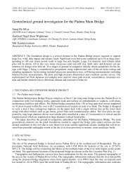
The length <strong>of</strong> the approach road <strong>viaduct</strong>s ranges from 720m to 875m long and comprise nom<strong>in</strong>al 38m<br />
<strong>spans</strong> (Figure 1). The number <strong>of</strong> <strong>spans</strong> ranges from 19 <strong>spans</strong> to 23 <strong>spans</strong>. The superstructure consists <strong>of</strong> simply<br />
supported 1800mm deep pre-tensioned precast concrete Super-T girders and a cast-<strong>in</strong>-situ composite deck<br />
slab. An asphalt layer is <strong>in</strong>stalled on the deck slab to form the wear<strong>in</strong>g surface <strong>of</strong> the bridge. Traffic barriers<br />
are located on both edges <strong>of</strong> the <strong>viaduct</strong>s.<br />
Figure 1. Typical elevation <strong>of</strong> <strong>viaduct</strong> <strong>spans</strong><br />
Figure 2. Typical cross sections <strong>of</strong> <strong>viaduct</strong> <strong>spans</strong><br />
2.2 Scheme Design<br />
Dur<strong>in</strong>g the scheme design phase, various options and alternatives were considered for the approach <strong>viaduct</strong>s.<br />
A two-level superstructure <strong>of</strong> the ma<strong>in</strong> bridge was the preferred option for the scheme design. The railway is<br />
located directly beneath the highway which presented a challenge <strong>in</strong> determ<strong>in</strong><strong>in</strong>g the structural arrangement<br />
<strong>of</strong> the approach <strong>viaduct</strong>s (Figure 2). Cont<strong>in</strong>u<strong>in</strong>g the two level steel truss to ground level would be too expen-<br />
135
sive, so different superstructure forms were considered to support the railway and highway to the approach<br />
embankments.<br />
The most cost effective solution for the <strong>viaduct</strong> <strong>spans</strong> was a typical beam and slab superstructure and this<br />
was selected as the most preferred option for the scheme design (Figure 3). Many beam types were considered<br />
although with the consideration <strong>of</strong> a precast yard, the pre-tensioned precast concrete Super-T girder<br />
proved to be the most economical solution.<br />
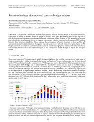
Two alternatives were considered for the alignment <strong>of</strong> the highway to separate the highway from the railway.<br />
One option was for the alignment <strong>of</strong> both carriageways to curve outwards <strong>in</strong> the same direction to overpass<br />
the railway. The other option was to split the alignment <strong>of</strong> the carriageways <strong>in</strong> two and curve the alignment<br />
outwards <strong>in</strong> opposite directions. This alternative <strong>of</strong> splitt<strong>in</strong>g the carriageways required the shortest<br />
distance <strong>of</strong> <strong>viaduct</strong> structure before reach<strong>in</strong>g the ground level and was thus selected as the preferred option<br />
(Figure 4).<br />
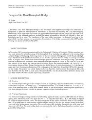
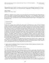
Figure 3. Ground view <strong>of</strong> the approach <strong>viaduct</strong>s lead<strong>in</strong>g onto<br />
the ma<strong>in</strong> bridge at the transition pier.<br />
Figure 4. Aerial view <strong>of</strong> the approach <strong>viaduct</strong>s at Mawa.<br />
2.3 Detailed Design<br />
The detailed design phase <strong>of</strong> the <strong>viaduct</strong> <strong>spans</strong> required a global l<strong>in</strong>ear static analysis, a global dynamic<br />
analysis and local grillage analysis to complete the design <strong>of</strong> the <strong>viaduct</strong> <strong>spans</strong>. The seismic analysis procedures<br />
were the most important and challeng<strong>in</strong>g process as this was the govern<strong>in</strong>g criteria for the majority <strong>of</strong><br />
the elements <strong>of</strong> the bridge.<br />
2.3.1 Design Criteria<br />
The design <strong>of</strong> the approach road <strong>viaduct</strong>s were carried out <strong>in</strong> accordance with British Standards BS 5400<br />
Steel, Concrete and Composite Bridges. However the British Standards do not cover the design <strong>of</strong> bridges for<br />
seismic events so AASHTO LRFD Bridge Design Specifications was used to design the <strong>viaduct</strong> <strong>spans</strong> for<br />
earthquake effects.<br />
The traffic load<strong>in</strong>g <strong>in</strong>cludes the HA and HB traffic load<strong>in</strong>g <strong>in</strong> accordance with the British Standards. In<br />
<strong>Bangladesh</strong>, a large number <strong>of</strong> vehicles are heavily loaded or overloaded. The HB 25 vehicle and the HB 45<br />
vehicles have both been considered <strong>in</strong> the design. The axle loads <strong>of</strong> these vehicles are 25T and 45T and reflect<br />
the current and potential load<strong>in</strong>g conditions <strong>in</strong> <strong>Bangladesh</strong> for the next 100 years.<br />
The most significant load<strong>in</strong>g condition for the <strong>viaduct</strong> <strong>spans</strong> is the seismic load<strong>in</strong>g. The <strong>viaduct</strong> <strong>spans</strong> are<br />
designed for a seismic event with a return period <strong>of</strong> 475 years. The follow<strong>in</strong>g parameters were used <strong>in</strong> the design<br />
to AASHTO LRFD:<br />
Acceleration coefficient: 0.143g<br />
Seismic Zone: 2<br />
Peak ground acceleration: 0.1414 m/s²<br />
Soil Pr<strong>of</strong>ile: Type II<br />
Site coefficient: 1.2<br />
The follow<strong>in</strong>g response modification factors were used <strong>in</strong> the design <strong>of</strong> these elements.<br />
Pier columns: 2.5<br />
Connections: 1.0<br />
Piles:<br />
2.0 (bend<strong>in</strong>g moments)<br />
Piles:<br />
1.0 (axial and shear forces)<br />
136
Under a seismic event, the top layers <strong>of</strong> the soil will liquefy to a depth <strong>of</strong> approximately 20m below the exist<strong>in</strong>g<br />
ground level. In the analysis and design for seismic, the lateral restra<strong>in</strong>t and sk<strong>in</strong> resistance <strong>of</strong> the soil<br />
has been ignored over the liquefiable depth.<br />
2.3.2 Superstructure<br />
The superstructure consists <strong>of</strong> simply supported 1800mm deep pre-tensioned precast concrete Super-T girders<br />
with a cast-<strong>in</strong>-situ composite deck slab. The girders are supported on lam<strong>in</strong>ated elastomeric bear<strong>in</strong>gs and have<br />
a nom<strong>in</strong>al span length <strong>of</strong> 38 metres. The superstructure is divided <strong>in</strong>to three modules for each <strong>viaduct</strong>. Expansion<br />
jo<strong>in</strong>ts are located at the abutments, the connection to the ma<strong>in</strong> bridge, and at <strong>in</strong>termediate locations to<br />
separate the modules. The superstructure is restra<strong>in</strong>ed horizontally at the piers which causes the structure to<br />
behave similar to a portal frame structure.<br />
2.3.3 Substructure<br />
The substructure consists <strong>of</strong> slender rectangular re<strong>in</strong>forced concrete pier columns. At the top <strong>of</strong> the piers, the<br />
width <strong>of</strong> the pier columns taper outwards to enhance the aesthetic appearance <strong>of</strong> the bridge (Figure 2). The<br />
pier columns are 1300mm to 1500mm thick and the width varies from 4000mm up to 6000mm at the top <strong>of</strong><br />
the column. The pier columns are supported on a re<strong>in</strong>forced concrete pile cap. The pile cap is located underneath<br />
the exist<strong>in</strong>g ground level to enhance the aesthetic appearance <strong>of</strong> the bridge. The foundations are bored<br />
piles with a diameter <strong>of</strong> 1200mm to 1500mm and extend to a depth <strong>of</strong> up to 50m below the exist<strong>in</strong>g ground<br />
level.<br />
3 DYNAMIC ANALYSIS OF THE MAIN BRIDGE VIADUCT SPANS<br />
3.1 General<br />
The AASHTO (2007) LRFD bridge design specification was selected as the most appropriate standard to use<br />
for the analysis and design for a seismic event for the <strong>viaduct</strong> <strong>spans</strong>. The purpose <strong>of</strong> a seismic analysis is to<br />
determ<strong>in</strong>e the force and displacement demands on the bridge under a specified seismic event applicable to the<br />
bridge environment. Earthquake load<strong>in</strong>g is an ultimate limit state event and it is not economical for a structure<br />
to be designed to behave with<strong>in</strong> the elastic range. The objective <strong>of</strong> the AASHTO (2007) standard is to design<br />
and detail the structure to potentially suffer damage dur<strong>in</strong>g a seismic event but should have a low probability<br />
<strong>of</strong> collapse.<br />
3.2 The multi-modal spectral analysis procedure<br />
In a multi-modal spectral analysis, structural analysis s<strong>of</strong>tware is used to perform a dynamic response analysis<br />
subject to the earthquake load<strong>in</strong>g <strong>in</strong>put data given <strong>in</strong> the form <strong>of</strong> acceleration response spectra. The analysis<br />
considers the vibration <strong>of</strong> the structure and analyses mass load cases to determ<strong>in</strong>e the natural frequency, period<br />
and mode shapes for a user def<strong>in</strong>ed number <strong>of</strong> modes. The spectral analysis then considers this data to<br />
compute the deflections, forces, moments and reactions <strong>in</strong> the structural elements.<br />
In accordance with AASHTO (2007), the follow<strong>in</strong>g considerations shall be used <strong>in</strong> a multi-modal spectral<br />
analysis:<br />
• A l<strong>in</strong>ear dynamic analysis us<strong>in</strong>g a three dimensional model shall be used to represent the structure.<br />
• The number <strong>of</strong> modes used <strong>in</strong> the analysis should be at least three times the number <strong>of</strong> <strong>spans</strong> <strong>in</strong> the<br />
model.<br />
• The member forces and displacements may be estimated by comb<strong>in</strong><strong>in</strong>g the respective response<br />
quantities (moment, force, displacement, or relative displacement by the Complete Quadratic<br />
Comb<strong>in</strong>ation (CQC) method.<br />
Chen & Duan (2003) and Caltrans (1999) describe some <strong>of</strong> the major considerations to be taken <strong>in</strong>to account<br />
when develop<strong>in</strong>g a structural computer model.<br />
• The number <strong>of</strong> degrees <strong>of</strong> freedom and the number <strong>of</strong> modes considered <strong>in</strong> the analysis shall be sufficient<br />
to capture at least 90% mass participation <strong>in</strong> the longitud<strong>in</strong>al and transverse directions.<br />
• A m<strong>in</strong>imum <strong>of</strong> three elements per column and four elements per span shall be used <strong>in</strong> the model.<br />
• The effective stiffness <strong>of</strong> the components should be used <strong>in</strong> order to obta<strong>in</strong> realistic evaluation <strong>of</strong> the<br />
structures period and displacement demands and <strong>in</strong>clude the effects <strong>of</strong> concrete crack<strong>in</strong>g, re<strong>in</strong>-<br />
137
forcements and axial loads for concrete components, residual stresses, out-<strong>of</strong>-straightness and the<br />
restra<strong>in</strong>ts <strong>of</strong> the surround<strong>in</strong>g soil <strong>of</strong> the piles.<br />
• For ductile concrete column members, effective moments <strong>of</strong> <strong>in</strong>ertia should be based on<br />
cracked section properties and can be determ<strong>in</strong>ed from the <strong>in</strong>itial slope <strong>of</strong> the moment curvature<br />
curve between the orig<strong>in</strong> and the po<strong>in</strong>t represent<strong>in</strong>g first yield <strong>of</strong> re<strong>in</strong>forcement. This is def<strong>in</strong>ed by<br />
the follow<strong>in</strong>g equation:<br />
• The effective torsional moment <strong>of</strong> <strong>in</strong>ertia ( ) <strong>of</strong> the concrete column shall be used and taken as<br />
20 percent <strong>of</strong> the uncracked section properties.<br />
• For prestressed concrete superstructures, is assumed the same as because prestress<strong>in</strong>g<br />
steel limits the crack<strong>in</strong>g <strong>of</strong> concrete superstructures.<br />
• Soil spr<strong>in</strong>g elements should be used to model the soil-foundation-structure <strong>in</strong>teraction.<br />
The <strong>in</strong>terpretation <strong>of</strong> the results and understand<strong>in</strong>g <strong>of</strong> the dynamic response <strong>of</strong> the structure is important <strong>in</strong><br />
develop<strong>in</strong>g the most economical design. The results also require <strong>in</strong>terpretation to determ<strong>in</strong>e the correct sectional<br />
properties to be used <strong>in</strong> the model. Further iteration <strong>of</strong> the analysis is required by alter<strong>in</strong>g the section<br />
properties <strong>of</strong> the cracked pier to represent the effective moment <strong>of</strong> <strong>in</strong>ertia. This alters the structural response<br />
and further iterations may be required.<br />
3.3 Global analysis <strong>of</strong> the ma<strong>in</strong> bridge <strong>viaduct</strong> <strong>spans</strong><br />
The superstructure <strong>of</strong> the ma<strong>in</strong> bridge <strong>viaduct</strong> <strong>spans</strong> was isolated <strong>in</strong>to three modules between the expansion<br />
jo<strong>in</strong>ts. As each module is isolated, the structural computer models can deal with each separate module, reduc<strong>in</strong>g<br />
the computational effort required. A typical structural computer model for a module is shown <strong>in</strong> Figure 5.<br />
The superstructure was modeled as a l<strong>in</strong>e beam <strong>in</strong> the model us<strong>in</strong>g the sectional properties <strong>of</strong> the full cross<br />
section. The alignment <strong>of</strong> the superstructure <strong>in</strong>cludes horizontal and vertical curves. The curved superstructure<br />
has been modeled as a series <strong>of</strong> straight members, as chords on the curve, between <strong>spans</strong> to represent the<br />
approximate geometry. The superstructure elements are connected to the vertical pier members. The vertical<br />
pier members were <strong>in</strong>itially modeled with the full gross sectional properties <strong>of</strong> the re<strong>in</strong>forced concrete pier.<br />
Cracked sectional properties were then <strong>in</strong>serted at the base members <strong>of</strong> cracked pier locations dur<strong>in</strong>g the iterations<br />
<strong>of</strong> the analysis.<br />
Pilecaps and piles are also modeled with correspond<strong>in</strong>g gross sectional properties. Member releases have<br />
also been used <strong>in</strong> the model to represent the rotational characteristics <strong>of</strong> the simply supported superstructure<br />
and the translational characteristics <strong>of</strong> the structure at expansion jo<strong>in</strong>t locations.<br />
Figure 5. Computer structural model used represent<strong>in</strong>g the module <strong>of</strong> the <strong>viaduct</strong> <strong>spans</strong> nearest to the ma<strong>in</strong> bridge.<br />
Force-displacement spr<strong>in</strong>g restra<strong>in</strong>ts were applied to nodes on the piles to represent the soil-foundationstructure<br />
<strong>in</strong>teraction. The stiffnesses <strong>of</strong> the spr<strong>in</strong>g restra<strong>in</strong>ts were calculated from the moduli <strong>of</strong> lateral subgrade<br />
reactions which were estimated from the N-values obta<strong>in</strong>ed from the standard penetrometer tests (SPT)<br />
carried out on boreholes drilled at the bridge location.<br />
All the applicable loads and load comb<strong>in</strong>ations were applied to the structural model which <strong>in</strong>cluded all<br />
dead loads, superimposed dead loads, live loads and other applicable transient loads. The global analysis for a<br />
seismic event however only <strong>in</strong>cludes the dead loads, superimposed dead loads, one third <strong>of</strong> the highway live<br />
load and the railway load<strong>in</strong>g.<br />
138
Under a seismic event however, it was found that the top layers <strong>of</strong> the soil would liquefy to a depth <strong>of</strong> approximately<br />
20 metres. Therefore a further, revised model was used for the seismic load cases with the node<br />
spr<strong>in</strong>g restra<strong>in</strong>ts on the piles removed over the liquefaction depth. This also significantly changed the structural<br />
response <strong>of</strong> the structure.<br />
The acceleration response spectrum (Figure 6) was <strong>in</strong>cluded <strong>in</strong> the model as spectral load data. This is then<br />
modeled <strong>in</strong> comb<strong>in</strong>ation with the applicable mass load case <strong>in</strong> the longitud<strong>in</strong>al and lateral directions for a<br />
specified number <strong>of</strong> modes. This result<strong>in</strong>g dynamic analysis determ<strong>in</strong>es the dynamic response <strong>of</strong> the structure.<br />
The response modification factors were also <strong>in</strong>put <strong>in</strong>to the model and used to determ<strong>in</strong>e the results <strong>of</strong> the<br />
analysis.<br />
Figure 6. Normalised acceleration response spectrum used for the <strong>viaduct</strong> <strong>spans</strong>.<br />
The results <strong>of</strong> the non-seismic and seismic load cases are then <strong>in</strong>terpreted to understand the behavior <strong>of</strong> the<br />
structure. The seismic load cases are also comb<strong>in</strong>ed with the other load cases such as creep and shr<strong>in</strong>kage effects.<br />
The seismic analysis was by far the govern<strong>in</strong>g load case for the substructure elements.<br />
It was found that the bend<strong>in</strong>g moments <strong>in</strong> the base <strong>of</strong> the piers were greater than the crack<strong>in</strong>g moment <strong>of</strong><br />
the re<strong>in</strong>forced concrete section. Therefore the period <strong>of</strong> the structure and the results <strong>of</strong> the analysis were not<br />
quite accurate. A moment curvature diagram was developed for the re<strong>in</strong>forced concrete sections <strong>of</strong> the pier to<br />
determ<strong>in</strong>e the effective moment <strong>of</strong> <strong>in</strong>ertia to be used <strong>in</strong> the model at the base <strong>of</strong> the cracked piers.<br />
A second iteration <strong>of</strong> the analysis was then carried out which gave more accurate structural periods and results.<br />
The results were then used to size the sections and def<strong>in</strong>e the re<strong>in</strong>forcement. Alterations to the cross<br />
section or re<strong>in</strong>forcement changed the effective moment <strong>of</strong> <strong>in</strong>ertia and further iterations <strong>of</strong> analysis were required<br />
until the correct balance was achieved.<br />
3.4 Second order analysis<br />
In a seismic event, the earth oscillates horizontally (and vertically), which causes the structure to translate. As<br />
the superstructure translates and the pier columns undergo curvature, the vertical superstructure forces on the<br />
column are <strong>of</strong>fset from the neutral axis <strong>of</strong> the column. In addition, the axial forces with<strong>in</strong> the column itself<br />
also act at an eccentricity to the column neutral axis. These eccentric load<strong>in</strong>gs cause additional bend<strong>in</strong>g moments<br />
<strong>in</strong> the column caus<strong>in</strong>g further translation and bend<strong>in</strong>g until equilibrium is achieved.<br />
In slender columns, the second order effects are much more significant and must be taken <strong>in</strong>to consideration<br />
<strong>in</strong>to the design. In a simplified calculation, a moment magnification factor is derived from the effective<br />
lengths <strong>of</strong> the members and used to amplify the bend<strong>in</strong>g moment results to be used <strong>in</strong> the design. This method<br />
is used as a simplified alternative to carry<strong>in</strong>g out a second order analysis and is known to generate conservative<br />
results.<br />
However <strong>in</strong> slender columns, the moment magnification method can result <strong>in</strong> an excessive <strong>in</strong>crease to the<br />
bend<strong>in</strong>g moments. Carry<strong>in</strong>g out a second order analysis requires more design effort, although the results are<br />
much more accurate and tend to be less conservative. The second order analysis, as carried out on the <strong>viaduct</strong><br />
<strong>spans</strong>, resulted <strong>in</strong> an <strong>in</strong>creased bend<strong>in</strong>g moment <strong>in</strong> the range <strong>of</strong> 20-50 percent depend<strong>in</strong>g on the slenderness.<br />
Due to the high depths <strong>of</strong> liquefaction, <strong>in</strong> a seismic event <strong>in</strong> comb<strong>in</strong>ation with slender piers, the translation <strong>of</strong><br />
the structure became quite significant which penalized the structure with second order effects.<br />
The second order analysis, carried out on the <strong>viaduct</strong> <strong>spans</strong>, resulted <strong>in</strong> an <strong>in</strong>creased bend<strong>in</strong>g moment <strong>in</strong><br />
the range <strong>of</strong> 20-50 percent depend<strong>in</strong>g on the slenderness. Due to the high depths <strong>of</strong> liquefaction dur<strong>in</strong>g a<br />
seismic event, the translation <strong>of</strong> the slender piers is quite significant, and the structure is subject to significant<br />
second order effects.<br />
It is important to note that the second order analysis should be carried out on the seismic load cases with a<br />
response factor <strong>of</strong> 1.0 which gives the actual deflections dur<strong>in</strong>g an earthquake. It is also important to calculate<br />
the second order effects on the total deflections <strong>of</strong> the structure for the comb<strong>in</strong>ed load case, rather than add<strong>in</strong>g<br />
the second order effects for each <strong>in</strong>dividual load case.<br />
139
4 PRE-TENSIONED PRECAST CONCRETE SUPER-T GIRDERS<br />
4.1 Background<br />
The Super-T girder is a bridge beam that was developed <strong>in</strong> Australia dur<strong>in</strong>g the 1990’s. Prior to the 1990’s,<br />
the precast concrete I-girder was one <strong>of</strong> the most commonly selected beam for medium span bridges. The I-<br />
girder is considered as an effective beam, although collaboration between the precast and construction <strong>in</strong>dustries<br />
identified that a beam could be developed with greater versatility that would result <strong>in</strong> significant improvements<br />
to design efficiency, manufactur<strong>in</strong>g, constructability, transportation and safety.<br />
Connal (2010) discusses the development and history <strong>of</strong> the Super-T beam which orig<strong>in</strong>ated from collaboration<br />
between the precast and construction <strong>in</strong>dustries and designers, and was aimed at satisfy<strong>in</strong>g several objectives,<br />
namely:<br />
• Easy manufacture and multi-use <strong>of</strong> a s<strong>in</strong>gle outer form for the full range <strong>of</strong> beam sections;<br />
• The ability to achieve a daily cast<strong>in</strong>g cycle to allow high production rates;<br />
• Use on bridges with <strong>spans</strong> <strong>of</strong> 18 to 36m, <strong>in</strong>clud<strong>in</strong>g for bridges with modest curvature;<br />
• M<strong>in</strong>imisation <strong>of</strong> on-site formwork and the creation <strong>of</strong> a cont<strong>in</strong>uous, safe deck work<strong>in</strong>g surface when<br />
the beams are assembled edge to edge immediately on <strong>in</strong>stallation;<br />
• Simplified prestress<strong>in</strong>g us<strong>in</strong>g straight pre-tensioned strand, with some strands debonded at the beam<br />
ends to control transfer stresses; and<br />
• A stable beam shape that does not require any added support to reta<strong>in</strong> lateral stability dur<strong>in</strong>g transfer<br />
or erection.<br />
Connal (2010) also states that many <strong>of</strong> the bridges constructed <strong>in</strong> the last ten years <strong>in</strong> Australia have been<br />
with superstructures us<strong>in</strong>g Super-T girders. The Super-T girder, for bridges <strong>in</strong> the 18m to 36m span range, has<br />
been found to be the most economical form <strong>of</strong> bridge beam for a wide range <strong>of</strong> applications. Australian bridge<br />
eng<strong>in</strong>eers work<strong>in</strong>g on <strong>in</strong>ternational projects have ‘exported’ this development to other countries <strong>in</strong>clud<strong>in</strong>g<br />
Vietnam, Philipp<strong>in</strong>es and Malaysia.<br />
The <strong>Padma</strong> Multipurpose Bridge Project will be the first project <strong>in</strong> <strong>Bangladesh</strong> to construct a bridge with<br />
Super-T girders. The <strong>in</strong>troduction <strong>of</strong> Super-T girders on this project will <strong>in</strong>troduce a new technology <strong>of</strong> precast<br />
bridge beams to the construction <strong>in</strong>dustry. The <strong>in</strong>dustry is currently limited to manufactur<strong>in</strong>g posttensioned<br />
beams and this project will highlight the potential benefits <strong>of</strong> manufactur<strong>in</strong>g pre-tensioned beams as<br />
an alternative for future projects <strong>in</strong> <strong>Bangladesh</strong>.<br />
4.2 Cross section<br />
The Super-T beam can be manufactured <strong>in</strong> sizes rang<strong>in</strong>g from 750mm – 1800mm deep and can be used on<br />
bridges with a span length <strong>of</strong> 18 – 38m, depend<strong>in</strong>g on the live load. The Super-T girder is a ‘T’ shaped girder<br />
and consists <strong>of</strong> a 75mm thick open top flange, a 100-120mm m<strong>in</strong>imum thick vertical web and a 260 - 325mm<br />
thick bottom flange (Figure 7a).<br />
Figure 7a. Typical Super-T girder cross section.<br />
Figure 7b. Typical Super-T girder cross section with composite deck slab.<br />
The top flange acts as formwork and the open section <strong>of</strong> the top flange has a recess to place sacrificial<br />
formwork. The girders are erected side by side and with the formwork <strong>in</strong> place, a flat safe work<strong>in</strong>g area is created<br />
to construct the deck slab (Figure 7b).<br />
The bottom flange conta<strong>in</strong>s the pre-tensioned strands which are arranged <strong>in</strong> rows <strong>of</strong> 50mm spac<strong>in</strong>g. Two<br />
strands are located <strong>in</strong> the top flange to assist <strong>in</strong> m<strong>in</strong>imiz<strong>in</strong>g tensile stresses dur<strong>in</strong>g transfer. The strands are<br />
straight for the full length <strong>of</strong> the beam. Internal diaphragms are located at <strong>in</strong>termediate locations (Figure 8 and<br />
9). The purpose <strong>of</strong> the <strong>in</strong>termediate diaphragm is to prevent any web distortions <strong>of</strong> the beam, particularly dur<strong>in</strong>g<br />
transport and erection. Solid end blocks are also located at the ends <strong>of</strong> the girders. The purpose <strong>of</strong> the end<br />
140
locks is to resist the burst<strong>in</strong>g stresses dur<strong>in</strong>g the stress<strong>in</strong>g <strong>of</strong> the girder. The end blocks are also required to<br />
<strong>in</strong>crease the shear capacity <strong>of</strong> the section where the shear forces are highest near the supports.<br />
Figure 8. Typical Super-T girder elevation.<br />
Figure 9. Typical Super-T girder plan view<br />
4.3 Materials<br />
The materials used for Super-T girders are designed to give the girder a design life <strong>of</strong> 100 years. The follow<strong>in</strong>g<br />
materials are typically used for Super-T girders.<br />
• Concrete: 28 day characteristic cube strength <strong>of</strong> 60 MPa.<br />
• Re<strong>in</strong>forcement: Grade 460 - 500 MPa<br />
• Prestress<strong>in</strong>g Strands: 7 wire, stress relieved, low relaxation strand 12.7 – 15.2mm diameter.<br />
Lower transfer strengths are nom<strong>in</strong>ated to ensure just adequate concrete strength at transfer and to ensure<br />
adequate production rates <strong>of</strong> manufactur<strong>in</strong>g. However it is also quite common for the precast manufacturers<br />
to use higher strengths <strong>of</strong> concrete so that the transfer strength is reached earlier and production rates are <strong>in</strong>creased.<br />
The maximum jack<strong>in</strong>g force <strong>of</strong> the strands is limited to 80 percent <strong>of</strong> the ultimate tensile strength.<br />
Failure <strong>of</strong> prestress<strong>in</strong>g strands under tension conta<strong>in</strong>s a high risk to safety and it is normal practice to limit the<br />
jack<strong>in</strong>g force to 75 percent <strong>of</strong> ultimate tensile strength.<br />
4.4 Design at transfer<br />
Transfer is the stage where the pre-tensioned strands are released to transfer an axial compression force to the<br />
precast beam. To allow gradual <strong>in</strong>troduction <strong>of</strong> prestress and to limit the stresses <strong>in</strong> the top <strong>of</strong> the beams at<br />
their ends, some <strong>of</strong> the strands are debonded from the concrete at the beam ends with plastic tape or tubes<br />
(Figure 8). A high prestress<strong>in</strong>g force is not required at the beam ends as the applied bend<strong>in</strong>g moments are not<br />
as high at these locations.<br />
4.5 Design for resistance to bend<strong>in</strong>g, shear and torsion<br />
The Super-T girder is designed to control crack<strong>in</strong>g at the serviceability limit state and to prevent failure at the<br />
ultimate limit state. Crack<strong>in</strong>g is controlled at the serviceability limit state by limit<strong>in</strong>g the compressive and<br />
tensile stresses <strong>in</strong> the concrete beam. At the ultimate limit state, the capacity <strong>of</strong> the beam is limited by the tensile<br />
stress <strong>in</strong> the steel prestress<strong>in</strong>g strands <strong>in</strong> the bottom flange.<br />
Depend<strong>in</strong>g on the live load criteria used <strong>in</strong> the design, it is usually found that the design is governed by<br />
bend<strong>in</strong>g. The objective dur<strong>in</strong>g the design is to m<strong>in</strong>imize the stresseses at transfer and the serviceability limit<br />
state whilst prevent<strong>in</strong>g failure at the ultimate limit state. The design usually requires a balance between the<br />
three design requirements to achieve the most efficient design.<br />
The prestress and vertical re<strong>in</strong>forcement <strong>in</strong> the webs <strong>of</strong> the girder is used to provide the shear and torsion<br />
capacity <strong>of</strong> the beam. The re<strong>in</strong>forcement extends from the bottom flange to the deck slab. After the deck slab<br />
is cast and becomes composite with the Super-T, the beam becomes a box section with good torsional stiffness.<br />
141
4.6 Manufactur<strong>in</strong>g<br />
The manufactur<strong>in</strong>g procedure <strong>of</strong> the Super-T girders is usually carried out <strong>in</strong> a precast facility or a precast<br />
yard. Long cast<strong>in</strong>g beds can be set up to allow the manufactur<strong>in</strong>g <strong>of</strong> several girders at a time. The steel re<strong>in</strong>forcement<br />
is usually prefabricated and then fixed <strong>in</strong> place with the prestress<strong>in</strong>g strands anchored to a bulkhead.<br />
The strands are then tensioned by jacks at one end and concrete is cast <strong>in</strong>to the moulds to the required<br />
shape <strong>of</strong> the girder. The bottom <strong>of</strong> the mould is usually movable to allow manufactur<strong>in</strong>g <strong>of</strong> different beam<br />
depths whilst ma<strong>in</strong>ta<strong>in</strong><strong>in</strong>g the same shape <strong>in</strong> the upper section. Inner moulds are also used to achieve the<br />
shape <strong>of</strong> the void and <strong>in</strong>termediate diaphragms. The webs <strong>of</strong> the Super-T and <strong>in</strong>termediate diaphragms are tapered<br />
to allow easy removal <strong>of</strong> beam from the outer mould and the <strong>in</strong>ner mould. Once the concrete has<br />
reached the transfer strength, the strands are cut and the beams are ready to be transported to site.<br />
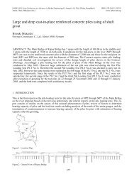
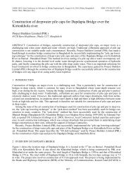
4.7 Transportation<br />
The Super-T beams have good stiffness properties for bend<strong>in</strong>g <strong>in</strong> the non-pr<strong>in</strong>cipal axis which gives the beam<br />
rigidity dur<strong>in</strong>g lift<strong>in</strong>g and transportation. The beams are easily transported us<strong>in</strong>g a prime mover at one end <strong>of</strong><br />
the beam and an <strong>in</strong>dependently steered j<strong>in</strong>ker at the other end <strong>of</strong> the beam (Figure 10).<br />
Figure 10. Transportation <strong>of</strong> Super-T girders us<strong>in</strong>g a prime mover and steered j<strong>in</strong>ker.<br />
4.8 Constructability<br />
Another benefit <strong>of</strong> the Super-T girders is the versatility <strong>in</strong> erection techniques. The girders can either be<br />
erected by mobile cranes, or they can be erected span by span with a launch<strong>in</strong>g gantry (Figure 11) where the<br />
girders are delivered to the most recently constructed span. Alternatively, the girders can be <strong>in</strong>stalled with a<br />
vertical lift erection gantry, where the girders are delivered via the ground level (Figure 12).<br />
The most dom<strong>in</strong>ant feature <strong>of</strong> the Super-T girder is the safe work<strong>in</strong>g platform that the beams create once<br />
erected. The outer flanges are erected edge to edge to the adjacent girder and sacrificial formwork is placed <strong>in</strong><br />
the open section. It is also possible to erect handrails on the edge girders, which will elim<strong>in</strong>ate any potential<br />
falls.<br />
Figure 11. Girders erected with a launch<strong>in</strong>g gantry.<br />
Figure 12. Girders erected with an erection gantry.<br />
5 RAILWAY VIADUCTS<br />
5.1 General Arrangement<br />
There are a two <strong>viaduct</strong>s support<strong>in</strong>g the railway, one on each side <strong>of</strong> the river. The length <strong>of</strong> the railway <strong>viaduct</strong>s<br />
ranges from 2.36km to 2.96km and consists <strong>of</strong> 38m <strong>spans</strong> similar to the approach road <strong>viaduct</strong>s. Railway<br />
stations are located on both the Mawa and Janjira sides <strong>of</strong> the river where the railway <strong>viaduct</strong> structures<br />
142
each the embankment level. The maximum vertical grade <strong>of</strong> the railway is 0.5% which causes the railways<br />
to extend a long way beyond the ma<strong>in</strong> bridge before reach<strong>in</strong>g the embankment level.<br />
5.2 Design Criteria<br />
The railway live load<strong>in</strong>g is one <strong>of</strong> the heaviest railway load<strong>in</strong>g criterion <strong>in</strong> the world. A provision has been<br />
made for a s<strong>in</strong>gle track broad gauge railway with a design operat<strong>in</strong>g speed <strong>of</strong> 160km/h for passenger tra<strong>in</strong>s<br />
and 125km/h for freight tra<strong>in</strong>s. The railway <strong>viaduct</strong> is designed to form part <strong>of</strong> the Indian Railways Dedicated<br />
Freight Corridor (DFC), with the railway live load consist<strong>in</strong>g <strong>of</strong> a series <strong>of</strong> 32.5T axle loads.<br />
5.3 Superstructure Design<br />
The superstructure consists <strong>of</strong> simply supported 2200mm deep precast, post-tensioned concrete I-girders with<br />
a composite deck slab. A track slab is <strong>in</strong>corporated <strong>in</strong>to the deck slab. End diaphragms and <strong>in</strong>termediate diaphragms<br />
are located between the beams. A walkway is <strong>in</strong>corporated <strong>in</strong>to the barrier and is located on both<br />
sides <strong>of</strong> the railway.<br />
The precast beams were selected due to cost efficiency and ease <strong>of</strong> construction. In order to withstand the<br />
heavy live load, the beams are spaced closely and tied together with the <strong>in</strong>termediate and end diaphragms.<br />
The purpose <strong>of</strong> diaphragms is to distribute the railway live load<strong>in</strong>g evenly between the beams such that all<br />
beams are effective <strong>in</strong> resist<strong>in</strong>g the load. The deep superstructure and closely spaced beams give the overall<br />
structure a high stiffness <strong>in</strong> the pr<strong>in</strong>cipal plane <strong>of</strong> bend<strong>in</strong>g which enables the structure to rema<strong>in</strong> with<strong>in</strong> the<br />
railway deflection limits.<br />
5.4 Substructure Design<br />
The substructure consists <strong>of</strong> tapered rectangular re<strong>in</strong>forced concrete pier columns with a rectangular headstock.<br />
The pier column is supported on re<strong>in</strong>forced concrete pile caps which are located below the ground<br />
level. The foundations are bored piles which extend to a depth <strong>of</strong> up to 50m below the exist<strong>in</strong>g ground level.<br />
Some <strong>of</strong> the piers are supported by the same pile cap as the approach road <strong>viaduct</strong> and the analysis and design<br />
has been carried out <strong>in</strong> parallel with the approach road <strong>viaduct</strong>s. Similar to the approach road <strong>viaduct</strong>s, the design<br />
<strong>of</strong> the substructure <strong>of</strong> the railway <strong>viaduct</strong>s was governed by the seismic load criteria.<br />
6 TRANSITION PIER<br />
The transition pier is a ‘Y’ shaped pier located at the <strong>in</strong>terface <strong>of</strong> the <strong>viaduct</strong> <strong>spans</strong> to the river <strong>spans</strong> and supports<br />
the end <strong>spans</strong> <strong>of</strong> the ma<strong>in</strong> bridge, the approach road <strong>viaduct</strong> structure and the railway <strong>viaduct</strong> structure<br />
(Figure 3). The transition pier also provides a location for the diversion <strong>of</strong> the gas pipe, power cables and<br />
telecommunication utilities <strong>of</strong>f the ma<strong>in</strong> bridge whilst also enclos<strong>in</strong>g an access stairwell for <strong>in</strong>spection, ma<strong>in</strong>tenance<br />
and emergency evacuations.<br />
The pier columns are designed with a void <strong>in</strong> the centre which encloses the access stairwell. Open<strong>in</strong>gs <strong>in</strong><br />
the columns are located at the ground level and the lower level <strong>of</strong> the steel truss to provide access for ma<strong>in</strong>tenance<br />
staff and for emergency evacuations. The columns also enclose the power cables and the telecommunications<br />
cables and transfer them underground disclosed from the public view. The gas pipe, which is located<br />
with<strong>in</strong> the truss, bends downwards at the transition pier and is attached to the riverside face <strong>of</strong> the pier. The<br />
pier has two levels <strong>of</strong> supports. The bottom level is a solid concrete pl<strong>in</strong>th between the columns and supports<br />
the end <strong>spans</strong> <strong>of</strong> the steel truss and the railway <strong>viaduct</strong> girders. The upper level is a re<strong>in</strong>forced concrete cross<br />
beam spann<strong>in</strong>g between the pier columns and supports the girders <strong>of</strong> the approach road <strong>viaduct</strong>.<br />
REFERENCES<br />
AASHTO LRFD Bridge Design Specifications, 4th Edition. 2007.<br />
British Standards, BS5400 Steel, Concrete and Composite Bridges.<br />
Caltrans, Seismic Design Criteria, Version 1.1. 1999. California Department <strong>of</strong> Transportation, Sacramento.<br />
Chen, W.F. & Duan, L., Eds. 2003. Earthquake Eng<strong>in</strong>eer<strong>in</strong>g Handbook, CRC Press, Boca Raton, FL.<br />
Connal, J.K. 2010. Super T Beams – A New Bridge Beam For Medium Span Bridges, FHWA Bridge Eng<strong>in</strong>eer<strong>in</strong>g Conference,“Highways<br />
for LIFE and Accelerated Bridge Construction”, Orlando, USA, 2010<br />
143