viaduct spans in Padma - Bangladesh Group of IABSE
viaduct spans in Padma - Bangladesh Group of IABSE
viaduct spans in Padma - Bangladesh Group of IABSE

Create successful ePaper yourself
Turn your PDF publications into a flip-book with our unique Google optimized e-Paper software.
2 APPROACH ROAD VIADUCTS<br />
2.1 General description<br />
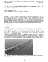
The <strong>Padma</strong> Multipurpose Bridge provides a fixed cross<strong>in</strong>g for a four lane dual carriageway highway and a<br />
s<strong>in</strong>gle l<strong>in</strong>e broad gauge railway over the <strong>Padma</strong> River <strong>in</strong> <strong>Bangladesh</strong>. The river bank on the northern approach<br />
<strong>of</strong> the bridge is located at Mawa. The river bank on the southern approach <strong>of</strong> the bridge is located at Janjira.<br />
The approach road <strong>viaduct</strong>s are designed to accommodate the road and railway onto the ma<strong>in</strong> bridge. The<br />
road connects to the exist<strong>in</strong>g Dhaka-Mawa highway on the Mawa side <strong>of</strong> the river. The road connects to the<br />
exist<strong>in</strong>g NH8 highway on the Janjira side <strong>of</strong> the river.<br />
The structure <strong>of</strong> the river <strong>spans</strong> <strong>of</strong> the ma<strong>in</strong> bridge is a two level steel truss with a composite deck slab.<br />
The railway is supported on the lower level and the highway is supported on a concrete deck slab at the upper<br />
level. The purpose <strong>of</strong> the approach road <strong>viaduct</strong>s is to transition the highway from the ma<strong>in</strong> bridge to the approach<br />
embankments. The alignment design <strong>of</strong> the approach road <strong>viaduct</strong>s has a complex arrangement. The<br />
highway is located above the railway which requires separation <strong>of</strong> the two carriageways otherwise the approach<br />
<strong>viaduct</strong>s would extend for kilometres beyond the ma<strong>in</strong> bridge.<br />
The northbound and southbound carriageways split outwards <strong>in</strong>to two structures away from the railway.<br />
As the <strong>viaduct</strong> structures become clear <strong>of</strong> the railway, the alignment transitions <strong>in</strong>to a steeper vertical grade to<br />
reach the approach embankments <strong>in</strong> the shortest distance possible. The southbound carriageway then curves<br />
back <strong>in</strong>wards to pass beneath the railway <strong>viaduct</strong> structure and to jo<strong>in</strong> up with the northbound carriageway.<br />
The length <strong>of</strong> the approach road <strong>viaduct</strong>s ranges from 720m to 875m long and comprise nom<strong>in</strong>al 38m<br />
<strong>spans</strong> (Figure 1). The number <strong>of</strong> <strong>spans</strong> ranges from 19 <strong>spans</strong> to 23 <strong>spans</strong>. The superstructure consists <strong>of</strong> simply<br />
supported 1800mm deep pre-tensioned precast concrete Super-T girders and a cast-<strong>in</strong>-situ composite deck<br />
slab. An asphalt layer is <strong>in</strong>stalled on the deck slab to form the wear<strong>in</strong>g surface <strong>of</strong> the bridge. Traffic barriers<br />
are located on both edges <strong>of</strong> the <strong>viaduct</strong>s.<br />
Figure 1. Typical elevation <strong>of</strong> <strong>viaduct</strong> <strong>spans</strong><br />
Figure 2. Typical cross sections <strong>of</strong> <strong>viaduct</strong> <strong>spans</strong><br />
2.2 Scheme Design<br />
Dur<strong>in</strong>g the scheme design phase, various options and alternatives were considered for the approach <strong>viaduct</strong>s.<br />
A two-level superstructure <strong>of</strong> the ma<strong>in</strong> bridge was the preferred option for the scheme design. The railway is<br />
located directly beneath the highway which presented a challenge <strong>in</strong> determ<strong>in</strong><strong>in</strong>g the structural arrangement<br />
<strong>of</strong> the approach <strong>viaduct</strong>s (Figure 2). Cont<strong>in</strong>u<strong>in</strong>g the two level steel truss to ground level would be too expen-<br />
135