viaduct spans in Padma - Bangladesh Group of IABSE
viaduct spans in Padma - Bangladesh Group of IABSE
viaduct spans in Padma - Bangladesh Group of IABSE

Create successful ePaper yourself
Turn your PDF publications into a flip-book with our unique Google optimized e-Paper software.
locks is to resist the burst<strong>in</strong>g stresses dur<strong>in</strong>g the stress<strong>in</strong>g <strong>of</strong> the girder. The end blocks are also required to<br />
<strong>in</strong>crease the shear capacity <strong>of</strong> the section where the shear forces are highest near the supports.<br />
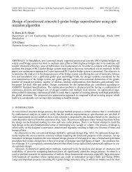
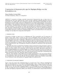
Figure 8. Typical Super-T girder elevation.<br />
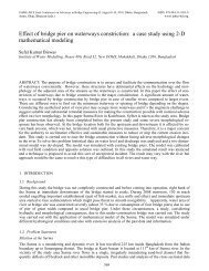
Figure 9. Typical Super-T girder plan view<br />
4.3 Materials<br />
The materials used for Super-T girders are designed to give the girder a design life <strong>of</strong> 100 years. The follow<strong>in</strong>g<br />
materials are typically used for Super-T girders.<br />
• Concrete: 28 day characteristic cube strength <strong>of</strong> 60 MPa.<br />
• Re<strong>in</strong>forcement: Grade 460 - 500 MPa<br />
• Prestress<strong>in</strong>g Strands: 7 wire, stress relieved, low relaxation strand 12.7 – 15.2mm diameter.<br />
Lower transfer strengths are nom<strong>in</strong>ated to ensure just adequate concrete strength at transfer and to ensure<br />
adequate production rates <strong>of</strong> manufactur<strong>in</strong>g. However it is also quite common for the precast manufacturers<br />
to use higher strengths <strong>of</strong> concrete so that the transfer strength is reached earlier and production rates are <strong>in</strong>creased.<br />
The maximum jack<strong>in</strong>g force <strong>of</strong> the strands is limited to 80 percent <strong>of</strong> the ultimate tensile strength.<br />
Failure <strong>of</strong> prestress<strong>in</strong>g strands under tension conta<strong>in</strong>s a high risk to safety and it is normal practice to limit the<br />
jack<strong>in</strong>g force to 75 percent <strong>of</strong> ultimate tensile strength.<br />
4.4 Design at transfer<br />
Transfer is the stage where the pre-tensioned strands are released to transfer an axial compression force to the<br />
precast beam. To allow gradual <strong>in</strong>troduction <strong>of</strong> prestress and to limit the stresses <strong>in</strong> the top <strong>of</strong> the beams at<br />
their ends, some <strong>of</strong> the strands are debonded from the concrete at the beam ends with plastic tape or tubes<br />
(Figure 8). A high prestress<strong>in</strong>g force is not required at the beam ends as the applied bend<strong>in</strong>g moments are not<br />
as high at these locations.<br />
4.5 Design for resistance to bend<strong>in</strong>g, shear and torsion<br />
The Super-T girder is designed to control crack<strong>in</strong>g at the serviceability limit state and to prevent failure at the<br />
ultimate limit state. Crack<strong>in</strong>g is controlled at the serviceability limit state by limit<strong>in</strong>g the compressive and<br />
tensile stresses <strong>in</strong> the concrete beam. At the ultimate limit state, the capacity <strong>of</strong> the beam is limited by the tensile<br />
stress <strong>in</strong> the steel prestress<strong>in</strong>g strands <strong>in</strong> the bottom flange.<br />
Depend<strong>in</strong>g on the live load criteria used <strong>in</strong> the design, it is usually found that the design is governed by<br />
bend<strong>in</strong>g. The objective dur<strong>in</strong>g the design is to m<strong>in</strong>imize the stresseses at transfer and the serviceability limit<br />
state whilst prevent<strong>in</strong>g failure at the ultimate limit state. The design usually requires a balance between the<br />
three design requirements to achieve the most efficient design.<br />
The prestress and vertical re<strong>in</strong>forcement <strong>in</strong> the webs <strong>of</strong> the girder is used to provide the shear and torsion<br />
capacity <strong>of</strong> the beam. The re<strong>in</strong>forcement extends from the bottom flange to the deck slab. After the deck slab<br />
is cast and becomes composite with the Super-T, the beam becomes a box section with good torsional stiffness.<br />
141