viaduct spans in Padma - Bangladesh Group of IABSE
viaduct spans in Padma - Bangladesh Group of IABSE
viaduct spans in Padma - Bangladesh Group of IABSE

You also want an ePaper? Increase the reach of your titles
YUMPU automatically turns print PDFs into web optimized ePapers that Google loves.
Under a seismic event, the top layers <strong>of</strong> the soil will liquefy to a depth <strong>of</strong> approximately 20m below the exist<strong>in</strong>g<br />
ground level. In the analysis and design for seismic, the lateral restra<strong>in</strong>t and sk<strong>in</strong> resistance <strong>of</strong> the soil<br />
has been ignored over the liquefiable depth.<br />
2.3.2 Superstructure<br />
The superstructure consists <strong>of</strong> simply supported 1800mm deep pre-tensioned precast concrete Super-T girders<br />
with a cast-<strong>in</strong>-situ composite deck slab. The girders are supported on lam<strong>in</strong>ated elastomeric bear<strong>in</strong>gs and have<br />
a nom<strong>in</strong>al span length <strong>of</strong> 38 metres. The superstructure is divided <strong>in</strong>to three modules for each <strong>viaduct</strong>. Expansion<br />
jo<strong>in</strong>ts are located at the abutments, the connection to the ma<strong>in</strong> bridge, and at <strong>in</strong>termediate locations to<br />
separate the modules. The superstructure is restra<strong>in</strong>ed horizontally at the piers which causes the structure to<br />
behave similar to a portal frame structure.<br />
2.3.3 Substructure<br />
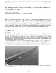
The substructure consists <strong>of</strong> slender rectangular re<strong>in</strong>forced concrete pier columns. At the top <strong>of</strong> the piers, the<br />
width <strong>of</strong> the pier columns taper outwards to enhance the aesthetic appearance <strong>of</strong> the bridge (Figure 2). The<br />
pier columns are 1300mm to 1500mm thick and the width varies from 4000mm up to 6000mm at the top <strong>of</strong><br />
the column. The pier columns are supported on a re<strong>in</strong>forced concrete pile cap. The pile cap is located underneath<br />
the exist<strong>in</strong>g ground level to enhance the aesthetic appearance <strong>of</strong> the bridge. The foundations are bored<br />
piles with a diameter <strong>of</strong> 1200mm to 1500mm and extend to a depth <strong>of</strong> up to 50m below the exist<strong>in</strong>g ground<br />
level.<br />
3 DYNAMIC ANALYSIS OF THE MAIN BRIDGE VIADUCT SPANS<br />
3.1 General<br />
The AASHTO (2007) LRFD bridge design specification was selected as the most appropriate standard to use<br />
for the analysis and design for a seismic event for the <strong>viaduct</strong> <strong>spans</strong>. The purpose <strong>of</strong> a seismic analysis is to<br />
determ<strong>in</strong>e the force and displacement demands on the bridge under a specified seismic event applicable to the<br />
bridge environment. Earthquake load<strong>in</strong>g is an ultimate limit state event and it is not economical for a structure<br />
to be designed to behave with<strong>in</strong> the elastic range. The objective <strong>of</strong> the AASHTO (2007) standard is to design<br />
and detail the structure to potentially suffer damage dur<strong>in</strong>g a seismic event but should have a low probability<br />
<strong>of</strong> collapse.<br />
3.2 The multi-modal spectral analysis procedure<br />
In a multi-modal spectral analysis, structural analysis s<strong>of</strong>tware is used to perform a dynamic response analysis<br />
subject to the earthquake load<strong>in</strong>g <strong>in</strong>put data given <strong>in</strong> the form <strong>of</strong> acceleration response spectra. The analysis<br />
considers the vibration <strong>of</strong> the structure and analyses mass load cases to determ<strong>in</strong>e the natural frequency, period<br />
and mode shapes for a user def<strong>in</strong>ed number <strong>of</strong> modes. The spectral analysis then considers this data to<br />
compute the deflections, forces, moments and reactions <strong>in</strong> the structural elements.<br />
In accordance with AASHTO (2007), the follow<strong>in</strong>g considerations shall be used <strong>in</strong> a multi-modal spectral<br />
analysis:<br />
• A l<strong>in</strong>ear dynamic analysis us<strong>in</strong>g a three dimensional model shall be used to represent the structure.<br />
• The number <strong>of</strong> modes used <strong>in</strong> the analysis should be at least three times the number <strong>of</strong> <strong>spans</strong> <strong>in</strong> the<br />
model.<br />
• The member forces and displacements may be estimated by comb<strong>in</strong><strong>in</strong>g the respective response<br />
quantities (moment, force, displacement, or relative displacement by the Complete Quadratic<br />
Comb<strong>in</strong>ation (CQC) method.<br />
Chen & Duan (2003) and Caltrans (1999) describe some <strong>of</strong> the major considerations to be taken <strong>in</strong>to account<br />
when develop<strong>in</strong>g a structural computer model.<br />
• The number <strong>of</strong> degrees <strong>of</strong> freedom and the number <strong>of</strong> modes considered <strong>in</strong> the analysis shall be sufficient<br />
to capture at least 90% mass participation <strong>in</strong> the longitud<strong>in</strong>al and transverse directions.<br />
• A m<strong>in</strong>imum <strong>of</strong> three elements per column and four elements per span shall be used <strong>in</strong> the model.<br />
• The effective stiffness <strong>of</strong> the components should be used <strong>in</strong> order to obta<strong>in</strong> realistic evaluation <strong>of</strong> the<br />
structures period and displacement demands and <strong>in</strong>clude the effects <strong>of</strong> concrete crack<strong>in</strong>g, re<strong>in</strong>-<br />
137